การแนะนำ
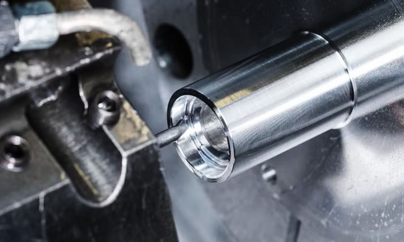
ใน การหล่อการลงทุน, คุณภาพของเปลือกเซรามิกจะกำหนดผิวสำเร็จโดยตรง, ความแม่นยำมิติ, และสมรรถนะทางกลของการหล่อขั้นสุดท้าย.
ในบรรดาชั้นเปลือกทั้งหมด, ที่ เสื้อคลุมหน้า เป็นสิ่งสำคัญที่สุดเนื่องจากมีการสัมผัสโดยตรงกับโลหะหลอมเหลวและสร้างรูปทรงและพื้นผิวของลวดลายขี้ผึ้งได้อย่างสมจริง.
ชั้นเคลือบผิวหน้าเรียบและหนาแน่นสามารถปรับปรุงคุณภาพการหล่อได้อย่างมากโดยการลดข้อบกพร่องที่พื้นผิว, ลดค่าเผื่อการตัดเฉือนให้เหลือน้อยที่สุด, และเพิ่มความแม่นยำของมิติ.
ในทางกลับกัน, ความหยาบของเปลือกมากเกินไปอาจส่งผลให้โลหะทะลุได้, การยึดเกาะของทราย, บ่อ, และลักษณะพื้นผิวที่ไม่ดี, ในที่สุดต้นทุนการผลิตและอัตราการปฏิเสธก็เพิ่มขึ้น.
ความหยาบของการเคลือบผิวหน้าของเปลือกหอยไม่ได้ถูกควบคุมโดยพารามิเตอร์ตัวเดียว. มันเป็นผลมาจากปฏิสัมพันธ์ที่ซับซ้อนระหว่างลักษณะของสารละลาย, วัสดุทนไฟ, กระบวนการปูนปั้น, คุณภาพลายขี้ผึ้ง, สภาพแวดล้อม, และการบำบัดด้วยความร้อน.
1. การกำหนดสูตรสารละลายและลักษณะทางรีโอโลยี
สารละลายเคลือบผิวหน้าเป็นเมทริกซ์ต่อเนื่องของพื้นผิวด้านในของเปลือกหอย. องค์ประกอบและพฤติกรรมการไหลเป็นปัจจัยพื้นฐานที่สุดของความขรุขระของพื้นผิวขั้นสุดท้าย.
การเปลี่ยนแปลงพารามิเตอร์ทุกครั้งภายในระบบสารละลายจะสร้างค่าโดยตรง, ผลที่วัดได้ต่อภูมิประเทศพื้นผิวที่หาย.
อัตราส่วนผงต่อของเหลวและพฤติกรรมรีโอโลยี
จากผงเป็นของเหลว (พี/แอล) อัตราส่วน - อัตราส่วนมวลของผงทนไฟต่อสารยึดเกาะ - เป็นตัวแปรที่สำคัญที่สุดในการควบคุมความหนืดของสารละลายและประสิทธิภาพการปรับระดับ.
ความหนืดมีความสัมพันธ์แบบผกผันกับปริมาณของเหลวอิสระ; เมื่ออัตราส่วน P/L เพิ่มขึ้น, ของเหลวอิสระลดลง, และความหนืดก็เพิ่มขึ้นอย่างรวดเร็ว.
ความสัมพันธ์นี้มีความไวสูงต่อความสมดุลของของแข็ง-ของเหลว.
เมื่ออัตราส่วน P/L สูงเกินไป (สารละลายที่มีความหนืดมากเกินไป):
- ความสามารถในการไหลลดลงอย่างมาก.
- สารละลายไม่สามารถปรับระดับรูปทรงด้วยกล้องจุลทรรศน์บนลวดลายขี้ผึ้งได้อย่างมีประสิทธิภาพ.
- รอยแปรง, เส้นจุ่ม, และสันเขาไหลจะ "แข็งตัว" ในสารเคลือบที่บ่มแล้ว.
- ความหยาบของพื้นผิวเพิ่มขึ้นอย่างมาก (ค่า Ra สามารถเกินได้ 3.2 ไมโครเมตร).
เมื่ออัตราส่วน P/L ต่ำเกินไป (สารละลายของเหลวมากเกินไป):
- สารเคลือบจะระบายออกจากพื้นผิวแนวตั้งอย่างรวดเร็ว.
- ความหนาของการเคลือบไม่เพียงพอช่วยให้อนุภาคปูนปั้นทะลุผ่านชั้นสารละลายได้, ติดต่อลายขี้ผึ้งได้โดยตรง.
- เส้นการไหลที่เกิดจากแรงโน้มถ่วงสร้างคลื่นที่ไม่สม่ำเสมอและข้อบกพร่องที่เป็นคลื่น.
ช่วงที่ปรับให้เหมาะสม: สำหรับสารละลายเคลือบหน้าแป้งซิลิกาโซลเซอร์คอนทั่วไป, อัตราส่วน P/L ที่เหมาะสมที่สุดอยู่ระหว่าง 3.2:1 และ 3.5:1 ตามน้ำหนัก. ภายในหน้าต่างนี้:
- ความหนืด (วัดโดยหมายเลข. 4 ซาห์น คัพ) คงที่ที่ 35‑45 วินาที.
- สารละลายมีความลื่นไหลเพียงพอที่จะเติมช่องขนาดเล็กในพื้นผิวลวดลาย.
- พฤติกรรม Thixotropic ป้องกันการระบายน้ำมากเกินไป.
- การเคลือบแบบเปียกทำให้มีความหนาสม่ำเสมอและเรียบเนียน, พื้นผิวเรียบ.
- ความหยาบของการเคลือบผิวหน้าขั้นสุดท้ายสามารถรักษาได้อย่างสม่ำเสมอด้านล่าง รา 1.6 ไมโครเมตร.
การเบี่ยงเบนไปจากหน้าต่าง P/L ในทิศทางใดทิศทางหนึ่ง จะทำให้ความหยาบเพิ่มขึ้นอย่างสม่ำเสมอ.
ซึ่งทำให้การควบคุม P/L ที่แม่นยำเป็นหนึ่งในกิจกรรมการประกันคุณภาพที่สำคัญที่สุดในโรงหล่อการลงทุน.
ขนาดอนุภาคและการกระจายขนาดผงทนไฟ
การกระจายขนาดอนุภาคของผงทนไฟเป็นปัจจัยวัตถุดิบหลักที่สองที่มีอิทธิพลต่อความหยาบของการเคลือบผิวหน้า.
กลไกมีความตรงไปตรงมา: หากผงประกอบด้วยอนุภาคส่วนใหญ่รวมตัวกันเป็นขนาดเดียว, ความหนาแน่นของการบรรจุต่ำ, ทิ้งช่องว่างคั่นระหว่างอนุภาคขนาดใหญ่.
ชั้นของสารละลายที่ได้จะมีรูพรุนและหยาบ, ด้วยหลุมอุกกาบาตขนาดเล็กจำนวนมากที่เพิ่มความหยาบของพื้นผิวและลดความต้านทานต่อการทะลุผ่านของโลหะ.
การกระจายขนาดอนุภาคที่เหมาะสมที่สุด ต้องใช้ความต่อเนื่อง, หลายรูปแบบ (ในอุดมคติแล้ว bimodal) การไล่สี.
อนุภาคละเอียดช่วยเติมเต็มช่องว่างระหว่างอนุภาคหยาบ, บรรลุความหนาแน่นสูงสุดในการบรรจุและความหนาแน่น, พื้นผิวเรียบหลังจากการบ่ม. การทดลองเพิ่มประสิทธิภาพของระบบแป้งเพทายแสดงให้เห็น:
| พารามิเตอร์ | ช่วงที่เหมาะสมที่สุด | ส่งผลกระทบต่อความหยาบ |
| เศษส่วนของอนุภาคหยาบ | 20−30 ไมโครเมตร | จัดให้มีกรอบโครงสร้าง. |
| เศษส่วนของอนุภาคละเอียด | 2−5 ไมโครเมตร | เติมช่องว่าง; ให้ความเรียบเนียน. |
| อัตราส่วนมวลเศษส่วนละเอียด | 30‐40% | เพิ่มความหนาแน่นของการบรรจุสูงสุด. |
| อนุภาคขนาดใหญ่ (>45 ไมโครเมตร) | <0.5% | ขจัดส่วนที่ยื่นออกมาและความหยาบเฉพาะจุด. |
ด้วยการกระจายตัวแบบไบโมดัลที่ได้รับการปรับปรุงนี้, ความหยาบของพื้นผิวลดลงไปมาก 40% เมื่อเปรียบเทียบกับผงชนิดเดียวที่มีขนาดอนุภาคเฉลี่ยเท่ากัน.
ชั้นเคลือบผิวหน้าที่ได้แทบไม่มีหลุมที่มีช่องว่างของอนุภาคที่มองเห็นได้.
นอกจากนี้, อนุภาคทั้งหมดที่มีขนาดใหญ่กว่า 45 µm จะต้องถูกลบออก โดยการกรองหรือการจำแนกอากาศ; สารปนเปื้อนที่มีขนาดใหญ่เกินไปจะสร้างก้อนเนื้อที่ยกขึ้นบนพื้นผิวเปลือกหอยซึ่งจะเพิ่มความหยาบเฉพาะจุดได้หลายเท่า.
ระบบสารยึดเกาะและสารเติมแต่งเชิงหน้าที่
ประเภทของสารยึดเกาะมีผลอย่างมากต่อความหยาบของพื้นผิว.
สารยึดเกาะหลักสามชนิดที่ใช้ในการหล่อการลงทุน ได้แก่ ซิลิกาโซล, เอทิลซิลิเกตไฮโดรไลเสต, และโซเดียมซิลิเกต—สร้างคุณภาพการเคลือบผิวหน้าที่แตกต่างกันอย่างเห็นได้ชัด:
| ระบบเครื่องผูก | ความหยาบผิวทั่วไป (รา) | ข้อดี | ข้อจำกัด |
| โซเดียมซิลิเกต | >6.3 ไมโครเมตร | ต้นทุนต่ำ; แห้งเร็ว. | เนื้อหยาบ; จำกัดเฉพาะการหล่อที่มีความแม่นยำต่ำ. |
| เอทิลซิลิเกต | µ3.2 µm | มีความแม่นยำดี; ค่าใช้จ่ายปานกลาง. | มีราคาแพงกว่า; ต้องมีการควบคุมไฮโดรไลซิสอย่างระมัดระวัง. |
| ซิลิกาโซล | <1.6 ไมโครเมตร | ความเรียบเนียนดีเยี่ยม; ความบริสุทธิ์สูง; อนุภาคคอลลอยด์ ~10-20 นาโนเมตร. | ต้นทุนที่สูงขึ้น; เวลาการอบแห้งนานขึ้น; ไวต่อการปนเปื้อน. |
ซิลิกาโซลเป็นสารประสานที่เลือกใช้สำหรับการหล่อการลงทุนที่มีความแม่นยำสูง เนื่องจากมีอนุภาคคอลลอยด์ที่เล็กมาก (โดยทั่วไป 10-20 นาโนเมตร).
ทำให้เกิดการก่อตัวของความหนาแน่น, ฟิล์มเจลต่อเนื่องที่มีความผิดปกติของพื้นผิวน้อยที่สุด.
สารเติมแต่งการทำงาน: การเติมสารลดแรงตึงผิวและสารปรับระดับเล็กน้อยสามารถปรับปรุงประสิทธิภาพการเปียกและการปรับระดับของสารละลายได้อย่างมาก โดยไม่ต้องเปลี่ยนแปลงเคมีของสารยึดเกาะพื้นฐาน:
- สารลดแรงตึงผิว (เช่น, สารทำให้เปียกแบบไม่มีไอออนิกที่ 0.1-0.3% ของมวลสารละลายทั้งหมด) ลดแรงตึงผิว, ส่งเสริมการแพร่กระจายที่สม่ำเสมอและป้องกันการเกิดรูเข็มหรือปล่องภูเขาไฟ.
- ตัวแทนปรับระดับ ยืดเวลาการไหลของฟิล์มสารละลายเปียก, ปล่อยให้มีรอยแปรง, เส้นจุ่ม, และสิ่งประดิษฐ์การใช้งานเล็กน้อยอื่น ๆ เพื่อรักษาก่อนการบ่ม.
อย่างไรก็ตาม, การใช้สารเติมแต่งมากเกินไป (>0.5%) อาจทำให้พื้นผิวหดตัวได้, หลุมอุกกาบาต, หรือรูเข็ม.
โดยทั่วไปช่วงการเติมที่เหมาะสมที่สุดคือ 0.1−0.5% โดยน้ำหนักของสารละลายทั้งหมด, ต้องการการสูบจ่ายที่แม่นยำและการควบคุมคุณภาพอย่างระมัดระวัง.
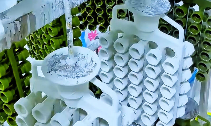
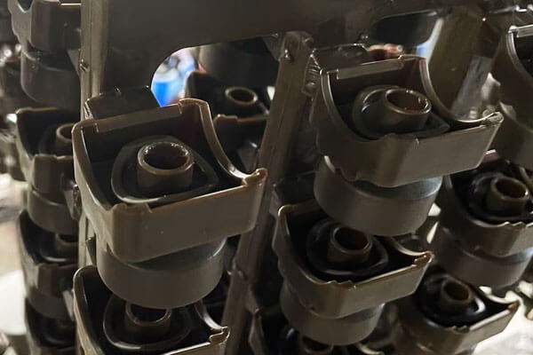
2. กระบวนการปูนปั้น: ตัวแปรปฏิบัติการที่สำคัญที่ควบคุมภูมิประเทศของพื้นผิวเชลล์
การฉาบปูนเป็นมากกว่าการใช้ทรายทนไฟบนพื้นผิวที่เปียก.
เป็นกระบวนการชี้ขาดที่กำหนดวิธีการยึดอนุภาคเซรามิกภายในสารละลายและ, เพราะเหตุนี้, พื้นผิวด้านในของเปลือกหอยจะถูกสร้างขึ้นอย่างไรหลังจากการอบแห้ง, ยิง, และการเทโลหะ.
สภาพการฝัง, ความสม่ำเสมอในการกระจาย, และความเสถียรของอนุภาคปูนปั้นส่งผลโดยตรงต่อรูปร่างระดับจุลภาคของชั้นเคลือบหน้าเปลือกหอยและท้ายที่สุดคือผิวสำเร็จของการหล่อ.

การจับคู่ขนาดอนุภาคระหว่างปูนปั้นและเคลือบหน้าเปียก
หลักการแรกของความสำเร็จในการฉาบปูนคือการบรรลุความสัมพันธ์ที่เหมาะสมระหว่างขนาดอนุภาคของทรายทนไฟและความหนาของชั้นเคลือบหน้าเปียก.
ผลกระทบของอนุภาคปูนปั้นขนาดใหญ่
เมื่ออนุภาคปูนปั้นหยาบเกินไป, ขนาดของมันเกินความหนาของฟิล์มสารละลาย.
ภายใต้เงื่อนไขเหล่านี้, อนุภาคจะแทรกซึมเข้าไปในการเคลือบเปียกและสัมผัสกับพื้นผิวลวดลายแว็กซ์โดยตรง.
ปรากฏการณ์นี้ทำให้เกิดรอยพิมพ์บนลวดลายขี้ผึ้งที่ยังคงอยู่ในเปลือกเซรามิกหลังจากการดีแว็กซ์และการเผา, ในที่สุดก็ปรากฏเป็นส่วนที่ยื่นออกมาหรือพื้นผิวที่ผิดปกติบนใบหน้าของเปลือกด้านใน.
อาจมีอนุภาคปูนปั้นขนาดใหญ่ด้วย:
- สร้างโซนความเข้มข้นของความเครียดในท้องถิ่น;
- ทำให้เกิดการเปลี่ยนแปลงความหนาของชั้นเคลือบ;
- เพิ่มความน่าจะเป็นของข้อบกพร่องในการเจาะโลหะ;
- เพิ่มความหยาบของเปลือกเคลือบหน้าอย่างเห็นได้ชัด.
ผลกระทบของอนุภาคปูนปั้นที่ละเอียดมากเกินไป
ในทางกลับกัน, อนุภาคปูนปั้นที่ละเอียดมากมีแนวโน้มที่จะอัดแน่นภายในชั้นสารละลาย.
ระยะห่างระหว่างอนุภาคที่ลดลงจะลดการซึมผ่านของเปลือกและเผยให้เห็นรูปทรงของอนุภาคละเอียดจำนวนมากบนพื้นผิวเปลือก.
ส่งผลให้:
- ส่วนที่ยื่นออกมาขนาดเล็กของพื้นผิวจะเด่นชัดมากขึ้น;
- การซึมผ่านของก๊าซลดลง;
- ความเสี่ยงของข้อบกพร่องในการหล่อที่เกี่ยวข้องกับแก๊สจะเพิ่มขึ้น;
- พื้นผิวของเปลือกจะหยาบขึ้นแม้จะมีขนาดอนุภาคเล็กลงก็ตาม.
ความสัมพันธ์ขนาดอนุภาคที่เหมาะสมที่สุด
ประสบการณ์ในการผลิตเชิงปฏิบัติได้แสดงให้เห็นว่าสภาวะการฝังที่มั่นคงที่สุดจะเกิดขึ้นได้เมื่อควบคุมขนาดอนุภาคปูนปั้นโดยเฉลี่ยที่ประมาณ:
50%–67% ของความหนาของชั้นเคลือบหน้าเปียก.
ภายใต้เงื่อนไขนี้:
- ประมาณครึ่งหนึ่งของแต่ละอนุภาคถูกฝังอยู่ในสารละลาย;
- ส่วนที่เหลืออยู่นอกชั้นเคลือบ;
- อนุภาคทรายไม่แทรกซึมเข้าไปในลวดลายของขี้ผึ้งหรือถูกสัมผัสจนหมดบนพื้นผิวเปลือก.
สำหรับความหนาของชั้นเคลือบผิวหน้าทั่วไป 0.3–0.5 มม., โดยทั่วไปขนาดปูนปั้นที่แนะนำคือ:
| ความหนาของชั้นเคลือบหน้าเปียก | ขนาดปูนปั้นที่แนะนำ |
| 0.30 มม | 120–140 ตาข่าย |
| 0.40 มม | 100–120 ตาข่าย |
| 0.50 มม | 80–100 ตาข่าย |
ระยะเวลาของกระบวนการ: หน้าต่างการใช้งานปูนปั้นที่สำคัญ
เวลาในการฉาบปูนมักถูกประเมินต่ำเกินไปในการปฏิบัติงานด้านการผลิต, แต่ก็มีผลกระทบอย่างชัดเจนต่อคุณภาพการฝังอนุภาคและสัณฐานวิทยาของพื้นผิว.
การใช้ปูนปั้นก่อนวัยอันควร
ทันทีหลังการเคลือบ, สารละลายยังคงเป็นของเหลวสูงและยังไม่มีการพัฒนาความหนืดเพียงพอที่จะรองรับอนุภาคทราย.
การใช้ปูนปั้นเร็วเกินไปอาจส่งผลให้:
- การโยกย้ายและการกระจัดของอนุภาค;
- การกระจายตัวของอนุภาคไม่สม่ำเสมอ;
- การสะสมทรายเฉพาะที่;
- การก่อตัวของส่วนที่นูนหยาบและเป็นคลื่น.
พื้นผิวของเปลือกที่ได้นั้นมักจะมีความแปรผันของความหยาบอย่างมีนัยสำคัญจากพื้นที่หนึ่งไปยังอีกพื้นที่หนึ่ง.
การประยุกต์ใช้ปูนฉาบล่าช้า
หากการฉาบปูนล่าช้าเกินไป, การเกิดเจลหรือการสร้างผิวหนังบางส่วนเริ่มต้นที่พื้นผิวของสารละลาย.
ภายใต้เงื่อนไขเหล่านี้:
- อนุภาคทรายไม่สามารถทะลุผ่านสารเคลือบได้อย่างเหมาะสม;
- การยึดเชิงกลไม่เพียงพอ;
- อนุภาคลอยตัวเกิดขึ้นบนพื้นผิว.
ในระหว่างการดำเนินการสร้างเปลือกหอยในเวลาต่อมา, อนุภาคที่เกาะติดกันอย่างหลวมๆ เหล่านี้มักจะหลุดออก, ทำให้เกิดหลุมและโพรงขนาดเล็กมากจนทำให้เปลือกมีความหยาบเพิ่มขึ้นอย่างมาก.
หน้าต่างปูนปั้นที่เหมาะสมที่สุด
สำหรับระบบการเคลือบผิวหน้าด้วยซิลิกาโซลทั่วไป, ระยะเวลาการฉาบปูนที่แนะนำคือ:
30–90 วินาทีหลังการเคลือบ.
ภายในช่วงเวลานี้:
- ความหนืดของสารละลายเพิ่มขึ้นถึงระดับที่เหมาะสม;
- ความคล่องตัวที่มากเกินไปก็หายไป;
- ความเป็นพลาสติกที่เพียงพอสำหรับการฝังอนุภาคที่มีประสิทธิภาพ.
เพราะเหตุนี้, อนุภาคทรายกระจายตัวสม่ำเสมอและยึดแน่น, ทำให้พื้นผิวเปลือกเรียบและสม่ำเสมอที่สุด.
ปัจจัยด้านสิ่งแวดล้อมที่มีอิทธิพลต่อคุณภาพปูนปั้น
สภาพแวดล้อมโดยรอบในระหว่างการฉาบปูนสามารถเปลี่ยนแปลงพฤติกรรมการฝังของอนุภาคและคุณภาพพื้นผิวของเปลือกได้อย่างมาก.
ในบรรดาตัวแปรด้านสิ่งแวดล้อมทั้งหมด, ปริมาณความชื้นของทราย และ ความชื้นสัมพัทธ์โดยรอบ เป็นผู้มีอิทธิพลมากที่สุด.
ปริมาณความชื้นของทรายปูนปั้น
ควรรักษาระดับความชื้นของวัสดุปูนปั้นไว้ด้านล่าง:
0.4%
ความชื้นที่มากเกินไปจะนำน้ำเข้าสู่บริเวณที่มีการแปลของสารละลาย, เปลี่ยนอัตราส่วนผงต่อของเหลวและทำให้ความหนืดเพิ่มขึ้นอย่างกะทันหัน.
ผลที่ตามมาได้แก่:
- ทรายที่ลอยตัวสะสม;
- การกระจายตัวของอนุภาคไม่สม่ำเสมอ;
- พันธะระหว่างชั้นที่อ่อนแอ;
- ข้อบกพร่องการแยกส่วน.
แม้ว่าข้อบกพร่องเหล่านี้อาจยังคงซ่อนอยู่ในระหว่างการสร้างเปลือก, มักจะปรากฏชัดเจนในระหว่างการล้างขี้ผึ้งและการเผา, ที่พวกเขาปรากฏเป็น:
- หลุมผิวน้ำ;
- ส่วนที่ยื่นออกมาไม่สม่ำเสมอ;
- พื้นที่ขรุขระ;
- การสเปย์เชลล์เฉพาะที่.
ความชื้นสัมพัทธ์โดยรอบ
ความชื้นสิ่งแวดล้อมที่แนะนำสำหรับงานปูนปั้นคือ:
40%–60% ความชื้นสัมพัทธ์
สภาพความชื้นต่ำ
เมื่อความชื้นต่ำเกินไป:
- น้ำผิวดินระเหยอย่างรวดเร็ว;
- การเกิดผิวหนังก่อนวัยอันควรเกิดขึ้น;
- อนุภาคทรายไม่สามารถฝังตัวได้เพียงพอ.
ผลลัพธ์ที่ได้คือการยึดเกาะของอนุภาคได้ไม่ดีและมีความหยาบของเปลือกเพิ่มขึ้น.
สภาพความชื้นสูง
เมื่อความชื้นสูงเกินไป:
- การอบแห้งจะช้ามาก;
- อนุภาคทรายยังคงจมอยู่ใต้แรงโน้มถ่วง;
- อนุภาคบางส่วนทะลุผ่านชั้นสารละลาย.
เงื่อนไขเหล่านี้จะเกิดขึ้นในที่สุด:
- พื้นผิวเปลือกไม่เรียบ;
- ข้อบกพร่องในการตกตะกอนของอนุภาค;
- ค่าความหยาบเพิ่มขึ้น.
3. สภาพพื้นผิวลวดลายและเทคนิคการเคลือบ
ชั้นเคลือบผิวหน้าจะเกิดขึ้นโดยตรงบนพื้นผิวลวดลายแว็กซ์. ดังนั้น, คุณภาพพื้นผิวของลวดลายและวิธีการเคลือบเป็นข้อกำหนดเบื้องต้นเพื่อให้ได้การเคลือบผิวหน้าที่มีความหยาบต่ำ.
การถ่ายโอนความหยาบของพื้นผิวลวดลาย
ตามกฎของโรงหล่อ, ความหยาบของพื้นผิวลวดลายจะถ่ายโอนไปยังชั้นเคลือบหน้าเปลือกหอยที่ประมาณ a 1:1 อัตราส่วน.
หากลายขี้ผึ้งมีรอยขีดข่วน, หลุม, เส้นการไหล, หรือข้อบกพร่องอื่น ๆ, แม้แต่สารละลายที่ได้รับการปรับให้เหมาะสมที่สุดในการปรับระดับก็ไม่สามารถเติมเต็มข้อบกพร่องขนาดใหญ่เหล่านี้ได้อย่างสมบูรณ์.
ความหยาบของเปลือกขั้นสุดท้ายจะสูงเท่ากับอย่างน้อยของลวดลาย.
ข้อกำหนดสำหรับการเคลือบผิวหน้าที่มีความหยาบต่ำ:
| พารามิเตอร์ | ข้อกำหนดที่จำเป็น | เหตุผล |
| ความหยาบผิวของเครื่องมือรูปแบบ | รา ≤0.4 ไมโครเมตร | เครื่องมือเหล็กหรืออลูมิเนียมขัดเงา, ไม่ใช่เรซินหรือปูนปลาสเตอร์. |
| พารามิเตอร์การฉีดขี้ผึ้ง | ที่ปรับให้เหมาะสม (ความดัน, อุณหภูมิ, อาศัยอยู่) | ป้องกันรอยไหล, ปิดเย็น, และการเกิดออกซิเดชันของพื้นผิว. |
| การตกแต่งหลังการฉีด | เช็ดหรือขจัดคราบไขมันเพื่อขจัดคราบเชื้อราและเศษไมโคร. | ขจัดข้อบกพร่องที่เกิดจากการปนเปื้อน. |
| ความหยาบของลวดลายสุดท้าย | รา ≤0.8 ไมโครเมตร | รับรองว่าการถ่ายโอนโดยตรงจะให้ความหยาบของเปลือกที่ยอมรับได้. |
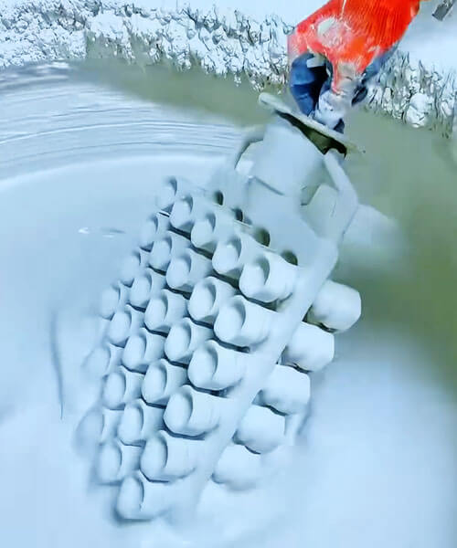
เทคนิคการเคลือบผิว
วิธีการทาสารละลายเคลือบผิวหน้ามีผลกระทบอย่างมากต่อความหยาบของพื้นผิวขั้นสุดท้าย.
เทคนิคการใช้งานหลักสามประการ—การแปรงฟัน, จุ่ม, และการเท - สร้างคุณภาพพื้นผิวที่แตกต่าง:
| เทคนิค | ข้อดี | ข้อจำกัด | ได้ความหยาบทั่วไป (รา) |
| การแปรงฟัน | ควบคุมพื้นที่เข้าถึงยากได้อย่างแม่นยำ; เหมาะสำหรับฟันผุภายในที่ซับซ้อน. | รอยแปรงอาจแข็งตัวจนกลายเป็นสารเคลือบได้; ขึ้นอยู่กับผู้ปฏิบัติงาน; ช้า. | 1.6−3.2 ไมโครเมตร |
| จุ่ม | เครื่องแบบ, แม้กระทั่งการเคลือบ; ผลผลิตสูง; อิทธิพลของผู้ปฏิบัติงานน้อยที่สุด. | ต้องใช้สารละลายของเหลวเพียงพอ; การออกแบบลวดลายต้องสามารถระบายน้ำได้. | <1.6 ไมโครเมตร (ดีที่สุด) |
| เท / การฉีดพ่น | เหมาะสำหรับลวดลายขนาดใหญ่หรือไม่สม่ำเสมอ; ความคุ้มครองที่ดี. | สามารถผลิตหยดและเส้นการไหลได้หากไม่ได้รับการควบคุมอย่างระมัดระวัง. | 1.6−2.5 ไมโครเมตร |
พารามิเตอร์การจุ่มที่เหมาะสมที่สุด:
- ความเร็วในการถอนรูปแบบ: พารามิเตอร์ที่สำคัญที่สุด. ความเร็วในการถอนอยู่ในช่วงของ 10−15 ซม./วินาที ทำให้เกิดความมั่นคง, ฟิล์มสารละลายสม่ำเสมอ.
เร็วเกินไป → ความหนาของชั้นเคลือบมากเกินไปและการวิ่ง; ช้าเกินไป → การเคลือบบางเกินไปและไม่ต่อเนื่อง. - ใช้เวลาอยู่ในสารละลาย: 5−15 วินาทีเพื่อให้เปียกโดยสมบูรณ์.
- เวลาระบายน้ำ: หลังจากถอนตัวแล้ว, ให้เวลา 10-20 วินาทีเพื่อให้สารละลายส่วนเกินระบายออกก่อนที่จะฉาบปูน.
วิธีการจุ่ม, เมื่อได้รับการควบคุมอย่างเหมาะสม, ได้ค่าความหยาบต่ำสุดและสม่ำเสมอที่สุด.
การแปรงฟันสามารถจับคู่กับการจุ่มสำหรับขนาดเล็กได้, ชิ้นส่วนที่ซับซ้อนแต่ทำให้เกิดความแปรปรวนของผู้ปฏิบัติงานมากขึ้น.
4. การประมวลผลหลังการสมัคร: การอบแห้ง, การทำลายล้าง, และการยิง
แม้หลังจากทาเคลือบหน้าและฉาบแล้วก็ตาม, ขั้นตอนการประมวลผลภายหลัง—การทำให้แห้ง, การทำลายล้าง, และการยิง—อาจทำให้เกิดหรือทำให้ข้อบกพร่องด้านความหยาบรุนแรงขึ้นได้.
ข้อบกพร่องที่แฝงอยู่จำนวนมากที่เกิดขึ้นในระยะก่อนหน้านี้จะแสดงออกมาในระหว่างการบำบัดทางกลความร้อน.
การอบแห้งและการบ่ม
กระบวนการทำให้แห้งคือส่วนที่สารยึดเกาะซิลิกาโซลเกิดเจล. อนุภาคซิลิกาคอลลอยด์รวมตัวกันเป็นโครงข่ายต่อเนื่อง, ล็อคอนุภาคทนไฟให้เข้าที่.
ต้องควบคุมการระเหยของน้ำจากพื้นผิวอย่างระมัดระวัง:
- หากแห้งเร็วเกินไป (อุณหภูมิสูง, การไหลของอากาศที่แข็งแกร่ง): พื้นผิวแห้งและก่อตัวเป็นผิวหนังในขณะที่ด้านในยังเปียกอยู่.
น้ำที่ติดอยู่จะระเหยออกไปในภายหลัง, ทำให้เกิดตุ่มหรือรอยแตกที่เปิดเป็นหลุมบนผิวเปลือกหอย. - หากแห้งช้าเกินไป (อุณหภูมิต่ำ, ความชื้นสูง): สารเคลือบสามารถย้อยหรือปูนปั้นสามารถเกาะตัวได้, สร้างพื้นผิวที่ไม่สม่ำเสมอ.
สภาวะการอบแห้งที่เหมาะสมที่สุด: อ่อน, สัมผัสสม่ำเสมอโดยมีการไหลเวียนของอากาศดีแต่ไม่มีการปะทะโดยตรง:
- อุณหภูมิ: 22−25°ซ.
- ความชื้นสัมพัทธ์: 50‐70%.
- เวลาในการอบแห้ง: 4‐8 ชั่วโมงสำหรับการเคลือบผิวหน้า, ขึ้นอยู่กับองค์ประกอบและความหนาของสารละลาย.
การทำลายล้าง
ขั้นตอนการล้างแว็กซ์ — การละลายลวดลายแว็กซ์ — จะต้องดำเนินการโดยใช้เครื่องทำความร้อนแบบควบคุม เพื่อป้องกันการขยายตัวของลวดลายจากการบิดเบือนพื้นผิวภายในของเปลือก.
หากอุณหภูมิเพิ่มขึ้นเร็วเกินไป, ขี้ผึ้งจะขยายตัวเกินกว่าที่เปลือกเซรามิกจะสามารถรองรับได้.
ผลที่ได้คือแรงดันภายในที่สามารถแตกร้าวได้, นูน, หรือทำให้ชั้นเคลือบหน้าเสียรูป, ทิ้งข้อบกพร่องที่พื้นผิวถาวรในการหล่อขั้นสุดท้าย.
แนวปฏิบัติที่ดีที่สุด: ในการนึ่งด้วยไอน้ำ (หม้อนึ่งความดัน), เพิ่มแรงดันไอน้ำไปที่ 0.6 MPa ภายใน 30 วินาที.
สิ่งนี้ทำให้มั่นใจได้อย่างรวดเร็ว, ให้ความร้อนสม่ำเสมอจากภายในสู่ภายนอก. ขี้ผึ้งจะละลายอย่างรวดเร็วและไหลออกมาก่อนที่จะเกิดการขยายตัวเนื่องจากความร้อนอย่างมีนัยสำคัญ.
เทคนิคนี้ช่วยรักษาพื้นผิวเรียบเดิมของการเคลือบผิวหน้า.
ยิง (การเผาผนึก)
สุดท้าย การเผาเปลือกเซรามิก ที่อุณหภูมิสูงทำหน้าที่เผาผลาญคาร์บอนที่ตกค้าง, กำจัดสารปนเปื้อนที่ระเหยง่าย, และเผาอนุภาคทนไฟเพื่อความแข็งแรง.
เงื่อนไขการเผาจะต้องได้รับการควบคุมเพื่อหลีกเลี่ยงการเสื่อมสภาพของพื้นผิว:
- เครื่องทำความร้อนอย่างรวดเร็ว: ก๊าซสลายตัวของสารยึดเกาะสามารถหลบหนีเร็วเกินไป, ทำให้เกิดหลุมอุกกาบาตบนผิวเปลือกหอย.
- อุณหภูมิการเผาที่มากเกินไป: การเผาผนึกมากเกินไปทำให้เกิดการก่อตัวของเฟสคล้ายแก้วและการไหล, สร้างระลอกคลื่น, พื้นผิวบิดเบี้ยว.
ตารางการยิงที่เหมาะสมที่สุดสำหรับการเคลือบผิวหน้าด้วยซิลิกา-โซล-เพทาย:
- รักษาอุณหภูมิ: 950−1,050°ซ.
- รอเวลา: 2‐3 ชั่วโมง.
- อัตราทางลาด: 4−6°C/นาที (ค่อย ๆ ปล่อยให้ก๊าซหลบหนี).
ภายในช่วงนี้, เปลือกได้รับความแข็งแรงเพียงพอสำหรับการเทโดยไม่มีการไหลหลอมเหลวมากเกินไป, ในขณะที่ชั้นเคลือบหน้ายังคงความเรียบเนียน, เนื้อสัมผัสหนาแน่นที่เกิดขึ้นในขั้นตอนก่อนหน้านี้.
ความหยาบยังคงต่ำอย่างต่อเนื่อง (รา ≤1.6 ไมโครเมตร) เมื่อยิงได้อย่างถูกต้อง.
5. การจัดการคุณภาพเชิงปฏิบัติและการตรวจสอบในกระบวนการ
การบรรลุความหยาบต่ำสม่ำเสมอจำเป็นต้องมีการตรวจสอบและควบคุมอย่างเป็นระบบตลอด การสร้างเปลือกหอย กระบวนการ. การตรวจสอบระหว่างดำเนินการที่แนะนำ ได้แก่:
| จุดตรวจ | มีการตรวจสอบพารามิเตอร์ | วิธีการทดสอบ | ช่วงที่ยอมรับได้ |
| ชุดสารละลาย | ความหนืด (ซาห์น คัพ) | เลขที่. 4 ถ้วย | 35‐45 วินาที |
| ชุดสารละลาย | อัตราส่วนกำไร/ขาดทุน | กราวิเมตริก | 3.2−3.5 : 1 |
| ชุดแป้ง | การกระจายขนาดอนุภาค | การเลี้ยวเบนของเลเซอร์ | ไบโมดัล; <1% >45 ไมโครเมตร |
| ปูนปั้น | ปริมาณความชื้น | ขาดทุนจากการอบแห้ง | <0.4% |
| สิ่งแวดล้อม | อุณหภูมิ / ความชื้น | ไฮโกรมิเตอร์ | 22−25°ซ / 40−60% ความชื้น |
| การดำเนินการเคลือบ | ความเร็วในการถอนแบบจุ่ม | ตัวจับเวลา / แท่นขุดเจาะที่ปรับเทียบแล้ว | 10−15 ซม./วินาที |
| การดำเนินการเคลือบ | โปรไฟล์ Dewaxing | เครื่องบันทึกเวลาแรงดัน | 0.6 MPa ใน 30 วินาที |
| ยิง | โปรไฟล์เตา | บันทึกเทอร์โมคัปเปิ้ล | 950−1,050°ซ, 2‐3 ชั่วโมง |
การตรวจสอบด้วยสายตาระหว่างกระบวนการ: การตรวจสอบชั้นเคลือบปูนปั้นเป็นระยะโดยใช้แว่นขยาย 10 เท่า สามารถตรวจพบสัญญาณเริ่มต้นของการยื่นปูนปั้นได้, การจับกันเป็นก้อน, หรือความคุ้มครองที่ไม่สมบูรณ์.
เครื่องวัดโปรไฟล์พื้นผิวแบบพกพา (ติดต่อหรือไม่ติดต่อ) สามารถใช้กับรูปแบบการเสียสละที่เลือกเพื่อตรวจสอบว่าบรรลุเป้าหมายความหยาบแล้ว.
6. การแปลงความหยาบของการเคลือบผิวหน้าเป็นประสิทธิภาพของพื้นผิวการหล่อขั้นสุดท้าย
ความสำคัญของความหยาบของการเคลือบผิวหน้าเปลือกหอยนั้นขยายไปไกลเกินกว่าขั้นตอนการผลิตเปลือกหอย.
ในการคัดเลือกนักลงทุน, เคลือบหน้าเซรามิกทำหน้าที่เป็น การจำลองเชิงลบของพื้นผิวส่วนประกอบสุดท้าย, หมายความว่าภูมิประเทศขนาดเล็กของมันถูกถ่ายโอนเกือบจะโดยตรงไปยังการหล่อในระหว่างการแข็งตัว.
เพราะเหตุนี้, แม้แต่ความแปรผันเล็กน้อยของความหยาบของเปลือกก็สามารถมีผลกระทบที่วัดได้ต่อประสิทธิภาพการทำงาน, อายุการใช้งาน, และมูลค่าทางการค้าของส่วนประกอบสำเร็จรูป.
สำหรับการหล่อที่มีความแม่นยำสูงซึ่งมีมูลค่าสูง, การควบคุมความหยาบของการเคลือบผิวหน้าไม่ได้เป็นเพียงข้อกำหนดด้านความสวยงามเท่านั้น แต่ยังเป็นพารามิเตอร์ทางวิศวกรรมที่สำคัญที่มีอิทธิพลต่อพฤติกรรมทางกลและการปฏิบัติงานของส่วนประกอบ.
กลไกการจำลองพื้นผิว
ระหว่างการเท, โลหะหลอมเหลวจะเติมเต็มทุกรอยยุบและส่วนที่ยื่นออกมาด้วยกล้องจุลทรรศน์บนพื้นผิวเปลือกเซรามิก.
หลังจากการแข็งตัว, การหล่อสร้างลักษณะพื้นผิวเหล่านี้ด้วยความเที่ยงตรงที่น่าทึ่ง.
แม้ว่าปัจจัยเช่น:
- การหดตัวของโลหะผสม,
- ความลื่นไหลของโลหะ,
- ปฏิกิริยาระหว่างแม่พิมพ์กับโลหะ,
- การเผาไหม้ของทราย,
สามารถปรับเปลี่ยนพื้นผิวขั้นสุดท้ายได้เล็กน้อย, ชั้นเคลือบหน้าเปลือกหอยยังคงเป็นปัจจัยสำคัญในการควบคุมความหยาบของการหล่อ.
ในกระบวนการหล่อการลงทุนที่แม่นยำที่สุด, อัตราการถ่ายโอนความหยาบระหว่างเปลือกและการหล่อมีตั้งแต่:
1:1 ถึง 1:1.3
ซึ่งหมายความว่าการเคลือบผิวหน้าด้วยค่า Ra เป็น 1.6 โดยทั่วไป μm จะทำให้พื้นผิวการหล่อมีความหยาบประมาณ 1.8–2.0 μm.
ผลกระทบต่อสมรรถนะทางกล
ต้านทานความเมื่อยล้า
ความผิดปกติของพื้นผิวทำหน้าที่เป็นรอยบากด้วยกล้องจุลทรรศน์และตัวทำให้เกิดความเครียด. ภายใต้การโหลดแบบวนรอบ, ภูมิภาคเหล่านี้กลายเป็นสถานที่ที่ต้องการสำหรับการเริ่มต้นแคร็ก.
พื้นผิวการหล่อที่เรียบเนียนยิ่งขึ้น:
- ปัจจัยความเข้มข้นของความเครียดลดลง;
- ลดพื้นที่เกิดรอยแตกของนิวเคลียส;
- อายุความเหนื่อยล้ายาวนานขึ้น;
- ปรับปรุงความน่าเชื่อถือภายใต้การโหลดแบบไดนามิก.
สิ่งนี้สำคัญอย่างยิ่งสำหรับ:
- ใบพัดกังหัน;
- ส่วนประกอบโครงสร้างเครื่องบิน;
- ชิ้นส่วนเครื่องยนต์ยานยนต์;
- อุปกรณ์หมุนความเร็วสูง.
การศึกษาพบว่าการลดความหยาบผิวจาก Ra 4.0 μm ถึง Ra 2.0 μmสามารถปรับปรุงอายุความเมื่อยล้าได้มากกว่า 20% ในโลหะผสมที่มีความแข็งแรงสูงบางชนิด.
ความต้านทานการกัดกร่อน
สัณฐานวิทยาของพื้นผิวมีอิทธิพลอย่างมากต่อพฤติกรรมการกัดกร่อน.
พื้นผิวที่ขรุขระประกอบด้วย:
- หุบเขาและรอยแยก;
- บริเวณอิเล็กโทรไลต์นิ่ง;
- เซลล์ไมโครกัลวานิก.
คุณสมบัติเหล่านี้เร่งความเร็ว:
- การกัดกร่อน;
- การกัดกร่อนของรอยแยก;
- การแตกร้าวจากการกัดกร่อนจากความเค้น.
สำหรับการปลูกถ่ายทางการแพทย์ที่ทำจากสเตนเลสสตีลและส่วนประกอบในการแปรรูปทางเคมี, พื้นผิวหล่อเรียบช่วยเพิ่มความต้านทานการกัดกร่อนในระยะยาวและความเข้ากันได้ทางชีวภาพได้อย่างมาก.
ประสิทธิภาพการสวมใส่
สภาพพื้นผิวเริ่มต้นส่งผลโดยตรงต่อกลไกการเสียดสีและการสึกหรอ.
พื้นผิวที่ขรุขระโดยทั่วไปจะนำไปสู่:
- ค่าสัมประสิทธิ์แรงเสียดทานที่สูงขึ้น;
- การสึกหรอจากการเสียดสีเพิ่มขึ้น;
- การกำจัดวัสดุได้เร็วขึ้น;
- การสร้างความร้อนมากขึ้น.
ส่วนประกอบเช่น:
- ใบพัดปั๊ม;
- ร่างกายวาล์ว;
- ส่วนประกอบไฮดรอลิก;
- ชิ้นส่วนเครื่องจักรกลเลื่อน,
ได้รับประโยชน์อย่างมากจากความหยาบผิวที่ลดลง.
อิทธิพลต่อประสิทธิภาพไดนามิกของของไหล
ในอุปกรณ์จัดการการไหล, ความหยาบของพื้นผิวส่งผลโดยตรงต่อพฤติกรรมของของไหล.
การยื่นออกมาของพื้นผิวด้วยกล้องจุลทรรศน์จะรบกวนชั้นขอบเขตและเพิ่มความปั่นป่วน, นำไปสู่:
- การสูญเสียแรงเสียดทานที่สูงขึ้น;
- ประสิทธิภาพการไหลลดลง;
- การใช้พลังงานเพิ่มขึ้น;
- แรงดันตกคร่อมมากขึ้น.
ปรากฏการณ์นี้มีความสำคัญอย่างยิ่งใน:
- ใบพัดกังหัน;
- ส่วนประกอบคอมเพรสเซอร์;
- ใบพัดปั๊ม;
- ช่องทางการไหลของการบินและอวกาศ.
สำหรับการใช้งานกังหันที่มีความแม่นยำ, แม้แต่การลดความหยาบของพื้นผิวลงเล็กน้อยก็สามารถปรับปรุงประสิทธิภาพของอากาศพลศาสตร์และลดต้นทุนการดำเนินงานตลอดอายุการใช้งานของอุปกรณ์ได้.
อิทธิพลต่อการเคลือบผิวและการรักษาพื้นผิว
การหล่อการลงทุนจำนวนมากจำเป็นต้องมีการดำเนินการรอง เช่น:
- การชุบด้วยไฟฟ้า;
- อโนไดซ์;
- เคลือบพีวีดี;
- การฉีดพ่นด้วยความร้อน;
- จิตรกรรม.
ความหยาบของพื้นผิวที่มากเกินไปอาจทำให้เกิด:
- ความหนาของการเคลือบไม่สม่ำเสมอ;
- การยึดเกาะของสารเคลือบไม่ดี;
- ข้อบกพร่องที่มีการแปล;
- ต้นทุนการตกแต่งเพิ่มขึ้น.
โดยการผลิตการหล่อที่มีพื้นผิวแบบหล่อที่เหนือกว่า, ผู้ผลิตสามารถลดปริมาณการขัดและการตัดเฉือนที่จำเป็นก่อนการรักษาพื้นผิวได้อย่างมาก.
ความแม่นยำของมิติและค่าเผื่อการตัดเฉือน
ความหยาบของพื้นผิวยังส่งผลต่อการควบคุมมิติด้วย.
โดยทั่วไปแล้วจะต้องมีพื้นผิวการหล่อแบบหยาบ:
- ค่าเผื่อการตัดเฉือนที่มากขึ้น;
- การดำเนินการบดเพิ่มเติม;
- ขั้นตอนการตกแต่งที่ครอบคลุมมากขึ้น.
สิ่งนี้เพิ่มขึ้น:
- ต้นทุนการผลิต;
- รอบเวลาการผลิต;
- ขยะวัสดุ.
ในทางกลับกัน, การหล่อแบบความหยาบต่ำมักใช้ในการใช้งานที่มีรูปร่างใกล้เคียงกัน, เพิ่มข้อได้เปรียบทางเศรษฐกิจสูงสุดของการหล่อการลงทุน.
คุณค่าทางสุนทรีย์และเชิงพาณิชย์
สำหรับผลิตภัณฑ์ที่รูปลักษณ์ภายนอกเป็นสิ่งสำคัญ, การตกแต่งพื้นผิวจะกลายเป็นตัวบ่งชี้คุณภาพที่สำคัญ.
ตัวอย่างได้แก่:
- การปลูกถ่ายทางการแพทย์;
- ส่วนประกอบอิเล็กทรอนิกส์สำหรับผู้บริโภค;
- ฮาร์ดแวร์ที่หรูหรา;
- ผลิตภัณฑ์โลหะตกแต่ง;
- ชิ้นส่วนยานยนต์ระดับพรีเมี่ยม.
มีพื้นผิวที่เรียบเนียนยิ่งขึ้น:
- ลักษณะการมองเห็นที่ดีขึ้น;
- ปรับปรุงคุณภาพการรับรู้;
- ปรับปรุงความพึงพอใจของลูกค้า;
- มูลค่าผลิตภัณฑ์ที่สูงขึ้น.
ในหลายกรณี, พื้นผิวของการหล่อจะเป็นตัวกำหนดการยอมรับของตลาดโดยตรง.
ความสัมพันธ์ระหว่างความหยาบของการเคลือบผิวหน้าและคุณภาพพื้นผิวการหล่อ
ประสบการณ์ทางอุตสาหกรรมที่กว้างขวางและการตรวจสอบเชิงทดลองได้สร้างความสัมพันธ์ที่ชัดเจนระหว่างความหยาบของเปลือกและผิวสำเร็จในการหล่อ.
| ความหยาบของผิวหน้า (รา, ไมโครเมตร) | ความหยาบในการหล่อทั่วไป (รา, ไมโครเมตร) | การใช้งานทั่วไป |
| ≤ 1.6 | ≤ 2.0 | ส่วนประกอบการบินและอวกาศ, การปลูกถ่ายทางการแพทย์, ใบพัดกังหัน, ชิ้นส่วนยานยนต์ระดับไฮเอนด์ |
| 1.6–3.2 | 2.0–4.0 | วาล์วอุตสาหกรรม, ปั๊ม, เครื่องจักรที่มีความแม่นยำ, ส่วนประกอบไฮดรอลิก |
| > 3.2 | > 4.0 | อุปกรณ์ก่อสร้าง, เครื่องจักรกลหนัก, การหล่อทางวิศวกรรมทั่วไป |
7. บทสรุป
ความหยาบผิวของการเคลือบผิวหน้าของเปลือกหล่อแบบลงทุนถูกควบคุมโดยกลไกการเชื่อมต่อแบบหลายปัจจัยแบบเต็มกระบวนการ, ครอบคลุมการออกแบบวัสดุสารละลาย, ข้อกำหนดการดำเนินงานปูนปั้น, การปรับสภาพรูปแบบขี้ผึ้ง, เทคนิคการเคลือบ, และกระบวนการเทอร์โมเคมีหลังการบำบัด.
การลงทุนในการควบคุมในแต่ละจุดเหล่านี้จะให้ผลประโยชน์แบบทบต้น: แต่ละขั้นตอนที่ได้รับการปรับปรุงให้เหมาะสมจะก่อให้เกิดคุณภาพพื้นผิวขั้นสุดท้ายซึ่งอาจมีลำดับความสำคัญที่ละเอียดกว่าเปลือกที่ผลิตโดยไม่มีการควบคุมดังกล่าว.
สำหรับโรงหล่อที่มุ่งมั่นที่จะตอบสนองความต้องการด้านวิศวกรรมที่มีความแม่นยำ—การบินและอวกาศ, ทางการแพทย์, ยานยนต์สมรรถนะสูง การแสวงหาความหยาบของการเคลือบผิวหน้าต่ำไม่ใช่โปรแกรมคุณภาพที่เป็นทางเลือก; มันเป็นความจำเป็นเชิงกลยุทธ์ในการแข่งขัน.