1. 소개
"판금"은 일반적으로 대략 금속 스톡을 말합니다. 0.2 mm 에 6 mm 두께 (업계 정의는 다양하다).
이 규모의 용접은 균형을 잡는 행위입니다.: 왜곡을 최소화하면서 사운드 조인트에 충분한 에너지를 전달합니다., 번스루(burn-through) 및 야금학적 손상.
좋은 결과를 얻으려면 적절한 프로세스 선택이 필요합니다 (점, 호, 마찰, 원자 램프, 브레이징), 열 입력 제어, 올바른 조인트 설계 및 견고한 검사.
2. 판금 용접이란??
판금 용접 구조를 만드는 데 사용되는 일련의 접합 기술입니다., 얇은 금속 스톡의 기능적 또는 미용적 접합 — 일반적으로 ≒0.2mm ~ 최대 6mm 산업 현장에서의 두께.
이 규모에서는 목표가 무거운 부분의 용접과 다릅니다: 동시에 사운드 조인트를 생성해야 합니다. 열 입력 최소화, 번스루 방지, 왜곡 제어, 표면 마감 유지 최종 조립 또는 가시 패널용.
간결한 정의
판금 용접은 제어된 국지적 에너지 적용입니다. (열의, 마찰 또는 야금) 조인트가 요구 사항을 충족하도록 두 개 이상의 시트 구성 요소를 융합하거나 야금적으로 결합하는 것 힘, 피로, 부식 및 미용 기준, 왜곡과 재작업을 허용 가능한 한도 내에서 유지하면서.
포함 내용 (프로세스 제품군)
판금 용접은 하나의 기술이 아니라 재료에 맞게 선택된 일련의 방법입니다., 두께, 조인트 형상 및 생산량:
- 융합 용접 — 모금속을 녹이고 일반적으로 필러를 첨가합니다. (예를 들어, gmaw/mig, GTAW/TIG, 원자 램프, 혈장).
- 저항용접 — 경계면의 전기 저항에 의해 열이 발생합니다. (예를 들어, 스팟 용접).
- 고체 용접 — 녹지 않고 결합 (예를 들어, 마찰 저어 용접 (FSW)).
- 브레이징 및 납땜 - 모재를 녹이지 않고 얇은 부재를 접합하기 위한 저융점 용가재의 모세관 흐름.
- 기계적 고정 (리벳, 클린칭) 접착제는 때때로 용접과 함께 사용됩니다..
3. 판금의 일반적인 용접 공정 - 심층
판금 제조에서는 열 입력을 제어하기 위해 선택된 소규모 용접 및 접합 기술을 사용합니다., 왜곡, 외관 및 사이클 시간.
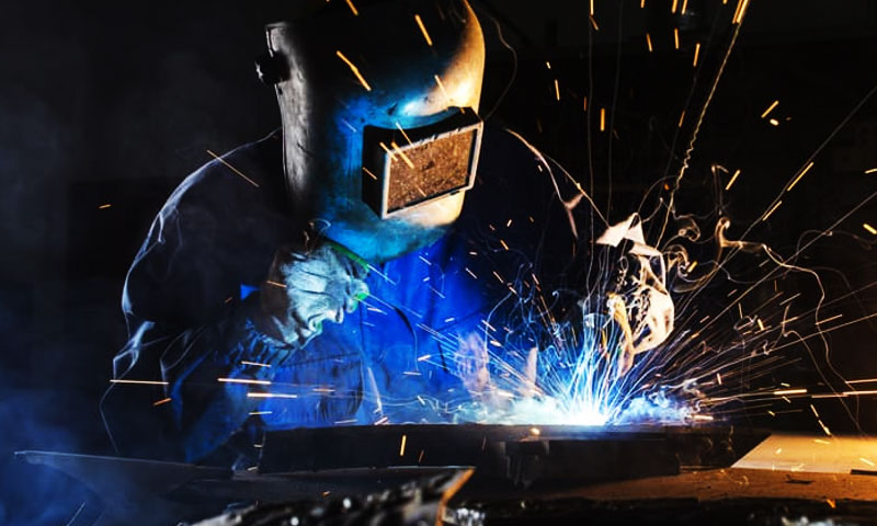
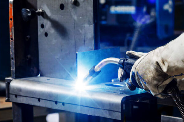
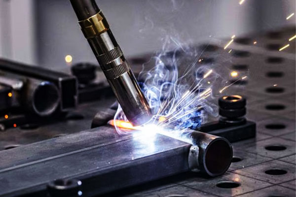
가스 금속 아크 용접 (GMAW / 나)
GMAW는 지속적으로 공급되는 소모성 와이어 전극과 공작물 사이에 전기 아크를 형성합니다..
아크는 보호 가스 분위기를 이온화합니다., 와이어 팁과 가공물 표면에 열 에너지를 전달하는 플라즈마 컬럼 생성.
금속은 전류에 의해 결정된 개별 모드로 와이어에서 용접 풀로 전달됩니다., 와이어 직경, 와이어 화학, 가스 조성 및 아크 역학:
- 단락 전송: 용융된 팁이 공작물에 잠깐 접촉하고 전류 스파이크로 인해 액적 분리가 빠르게 발생합니다.; 방울당 에너지가 낮다, 제한된 침투와 최소한의 열 입력 제공 - 매우 얇은 시트에 이상적.
- 구형 전송: 더 큰, 중력의 영향을 받은 물방울이 형성되고 낙하합니다.; 이 모드는 불안정하고 스패터가 발생합니다..
- 스프레이 이송: 고전류, 아크를 가로질러 미세한 물방울이 지속적으로 전달됨; 증착이 높고 침투력이 깊지만 열 입력이 더 높습니다. (두꺼운 부분에 더 적합).
- 펄스 스프레이: 펄스당 단일 액적 전달을 생성하는 제어된 피크-베이스 전류 파형 - 낮은 평균 열 입력과 스프레이 같은 액적 분리를 결합하여 얇은 시트에서 중간 크기 시트의 우수한 마감 처리.
전자기력 (핀치 효과) 표면 장력이 물방울 형성과 분리를 지배합니다..
용접 풀 역학 (유체 흐름, 황/산소의 영향을 받는 마랑고니 대류, 및 전자기 교반) 비드 모양 및 희석 제어.
차폐 가스 구성은 아크 안정성에 영향을 미칩니다, 금속 전달 모드 및 침투 (예를 들어, CO2는 물방울 크기와 스패터를 증가시킵니다.; 아르곤-산소 혼합물은 더 낮은 전류에서 스프레이 이동을 안정화합니다.).
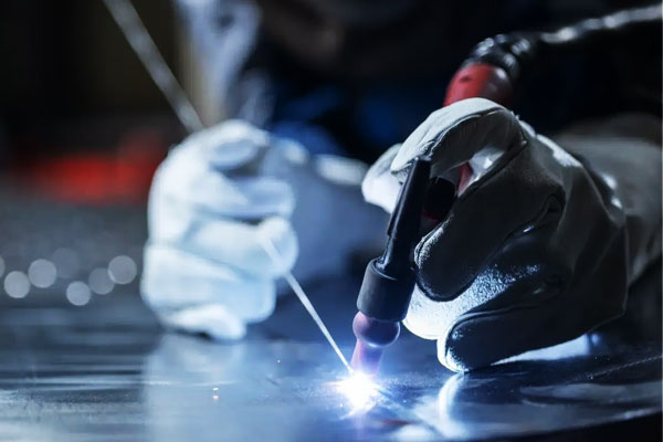
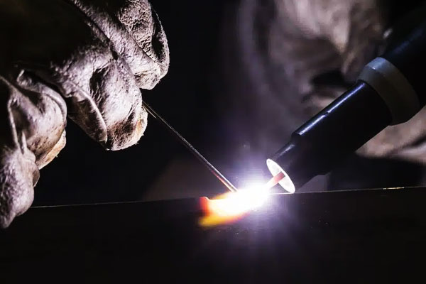
가스 텅스텐 아크 용접 (GTAW / 싸움)
GTAW는 비소모성 텅스텐 전극 안정적인 아크를 유지하기 위해.
아크가 수축되어 모재에 부착됩니다., 이온화된 기체를 통해 열을 전달하는 것 (혈장).
전극이 소모되지 않기 때문에, 필러 금속 (사용하는 경우) 용접 풀에 수동 또는 자동으로 공급됩니다..
주요 신체적 측면:
- 아크 기둥과 열 집중: TIG 아크는 좁고 제어가 매우 쉽습니다.; 전류 또는 토치 각도의 작은 변화는 국지적 열 입력에 직접적인 영향을 미칩니다..
- 차폐 및 아크 화학: 불활성 가스 (일반적으로 아르곤) 산화를 방지; 알루미늄 AC TIG용,
교대 극성은 산화물 세척을 생성합니다. (전해연마) 전극-양성 반주기 동안 효과 및 전극-음성 반주기 동안 침투 - 이는 끈질긴 산화알루미늄 표피를 깨뜨리는 데 매우 중요합니다.. - 열전도 및 복사 냉각: 전극이 더 차갑고 열이 가공물로 흐르기 때문입니다., TIG는 웅덩이 크기를 미세하게 제어하여 예측 가능한 융합 영역을 생성합니다..
- 아크 개시 및 안정성: 고주파 또는 리프트 스타트 시스템을 통해 오염 없이 아크 발생을 제어할 수 있습니다.; 전극 선택 (토리아, 세라믹화된, 란탄화된) 다양한 전류 범위에 맞게 전자 방출 및 아크 안정성을 조정합니다..
TIG를 사용하면 정밀한 열 제어가 가능하고 용융 풀 난류가 최소화됩니다., 아크 안정성과 청결함이 성능을 좌우하는 얇은 시트 및 표면 용접에 탁월합니다..
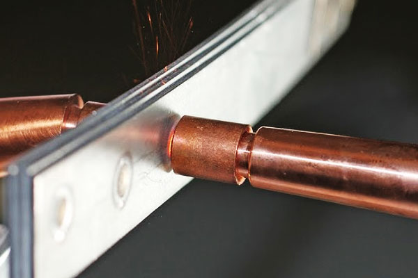
저항 점용접 (RSW)
저항점용접은 줄 가열 과정: 압축 전극 힘이 긴밀한 접촉을 유지하는 동안 높은 전류가 접촉 시트 스택을 통해 강제됩니다..
접점 인터페이스의 국부 저항 (벌크 시트 저항은 더 적습니다.) 전기에너지를 빠르게 열로 변환, 국부적인 용융 및 용접 너겟 형성 유발.
중요한 기계적 포인트:
- 접촉 저항과 벌크 저항: 초기 인터페이스 저항이 가열을 지배합니다.; 재료가 부드러워지고 용융된 금속이 형성됨에 따라, 저항은 동적으로 변화합니다. 프로세스 제어는 이러한 전환을 고려해야 합니다..
- 전극의 힘과 열 분포: 압축력은 산화물을 압착하고 접촉 저항을 감소시킵니다.; 또한 용융 금속을 구속하고 배출을 방지하여 너겟 형상을 제어합니다..
- 열확산 및 냉각: 전류가 차단된 후, 유지 시간과 전극 냉각으로 열을 추출하고 너겟을 응고시킵니다.; 전극 냉각 (수냉식 구리 전극) 너겟 크기와 반복성을 제어하는 데 중요합니다..
- 소재 및 코팅 효과: 코팅 (아연 도금, 유기농 코팅) 접촉 저항이 바뀌고 기화될 수 있습니다., 열 국소화 및 전극 수명에 영향을 미치므로 이에 따라 일정을 조정해야 합니다..
RSW는 근본적으로 전기-열-기계 프로세스입니다., 열적 및 기계적 변수는 밀리초 단위로 상호 작용하여 야금학적 결합을 생성합니다..
마찰 저어 용접 (FSW)
FSW는 고체, 열-기계적 접합 공정. 회전하는, 프로파일링된 도구 (어깨 + 핀) 관절 속으로 들어가 그것을 따라 횡단한다..
작동하는 메커니즘에는 다음이 포함됩니다.:
- 마찰 가열: 회전하는 숄더와 핀은 공구-작업물 인터페이스에서 마찰로 인해 열을 발생시킵니다., 국부적으로 온도를 소성 유동성이지만 서브멜팅 상태로 높이는 것.
- 재료의 가소화된 흐름 및 교반: 핀의 기하학적 구조로 인해 앞쪽 가장자리의 재료가 핀 주위로 흐르고 웨이크에서 통합됩니다., 공극을 닫고 초기 산화막을 깨뜨려 미세한 입자의 동적으로 재결정화된 "교반 영역"이 생성됩니다..
- 기계적 단조 작용: 어깨가 단조압력을 가한다, 교반된 재료를 통합하고 융합 관련 다공성이 없는 결함 없는 접합을 생성합니다..
- 미세구조의 진화: 심한 소성 변형과 동적 재결정화로 입자가 미세해지고 종종 융합 용접에 비해 우수한 기계적 특성을 생성합니다..
FSW는 녹는 것을 방지하기 때문에, 응고 결함을 제거합니다. (예를 들어, 다공성, 뜨거운 크래킹) 낮은 왜곡을 생성합니다.; 하지만, 성공적인 용접을 위해서는 견고한 지지와 도구 형상 및 공정 운동학의 세심한 제어가 필요합니다..
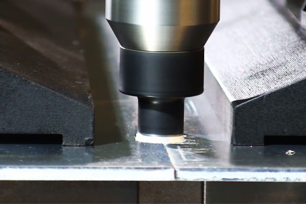
레이저 빔 용접 (LBW) & 하이브리드 레이저 아크 용접
레이저 용접은 표면에 결합되는 고도로 시준된 빔으로 에너지를 전달합니다., 두 가지 기본 전도 모드 생성:
- 전도 모드: 낮은 전력 밀도에서 레이저는 표면을 가열하고 전도를 통해 재료를 녹입니다.; 침투가 얕고 열영향부 (위험요소) 겸손하다.
- 열쇠구멍 모드: 높은 전력 밀도에서 빔은 증기로 채워진 공동을 생성하는 금속 기둥을 기화시킵니다. (열쇠구멍). 열쇠 구멍 벽의 강렬한 흡수로 인해 열쇠 구멍이 유지되면서 깊은 침투가 발생합니다.; 열쇠 구멍 주변의 반동 압력과 유체 역학이 용융 풀의 흐름과 안정성을 제어합니다..
주요 물리적 요인은 다음과 같습니다. 흡수 (재료, 표면 상태), 반사율 (Al 및 Cu와 같은 반사율이 높은 금속은 결합을 줄입니다.), 그리고 열쇠구멍 안정성 (조인트 핏업과 오염물질의 존재에 민감함).
하이브리드 레이저-아크 용접은 레이저와 아크를 결합합니다. (보통 MIG) — 호는 갭 브리징을 향상시킵니다., 접합부를 예열하고 필러를 공급하는 반면 레이저는 깊은 침투력과 좁은 HAZ를 제공합니다..
아크는 용융 금속 가용성을 높이고 작은 간격에 대한 민감도를 감소시키기 때문에 시너지 효과가 발생합니다., 레이저는 침투를 제어하고 왜곡을 줄입니다..
플라즈마 아크 용접 (PAW)
PAW는 플라즈마 가스를 강제로 생성하여 수축된 플라즈마 제트를 생성합니다. (아르곤, 수소 혼합물) 텅스텐 전극 주위의 미세한 노즐을 통해.
수축은 가스 온도와 이온화를 증가시킵니다., 집중적으로 생산, 어느 쪽이든 사용할 수 있는 고에너지 밀도 아크:
- 전송 모드: 아크가 공작물에 부착되고 열 전달이 집중됩니다.; 더 깊은 침투에 적합.
- 비양도 (조종사) 방법: 특수한 예열 또는 점화 작업을 위해 전극과 노즐 사이에 아크가 유지됩니다..
플라즈마 제트의 더 높은 에너지 밀도와 층류 흐름은 기존 TIG보다 더 나은 제어로 안정적인 침투를 생성합니다.;
가스화학 (H2첨가) 취약한 합금에서 잠재적인 수소 픽업을 희생하여 엔탈피와 침투성을 증가시킵니다..
따라서 노즐 형상과 가스 흐름 제어는 호 모양을 결정하는 중요한 매개변수입니다., 침투 및 용접 풀 동작.
산소 연료, 브레이징 및 납땜 (얇은 게이지용, 비구조적)
이들은 모세관 및 온도 제어 접합 방법 융합용접보다는:
- 산소 연료 (불꽃) 용접/브레이징: 연소 불꽃 (O2 + 연료 가스) 국소적인 열 공급.
납재 브레이징에 있어서 (모재보다 녹는점이 낮음) 모재 금속을 녹이지 않고 모세관 현상에 의해 조인트 간극으로 흐르도록 가열됩니다..
화염 화학 및 플럭스는 산화물 용해 및 습윤을 관리합니다.. 순산소 용접 (퓨전) 모재와 충전재를 녹입니다. 열 제어가 거칠기 때문에 시트 작업에는 드뭅니다.. - 브레이징: 의지하다 습식- 용융된 필러는 모재 금속 표면 위로 흘러서 부착되어야 합니다., 산화물 변위; 플럭스 또는 제어된 대기는 산화물을 제거하고 습윤을 촉진합니다..
모세관 현상이 필러 분포를 제어합니다.; 공동 정리가 중요하다 (일반적인 브레이징 간격 0.05–0.15 mm). - 납땜: 브레이징과 유사하지만 온도가 더 낮습니다. (<450 ℃); 전자 장치 및 조명 어셈블리의 표면 장력 및 응고 제어 조인트 무결성.
모재는 녹지 않기 때문에, 브레이징 및 납땜은 왜곡을 최소화하며 이종 금속 접합에 매우 적합합니다.; 성공은 필러의 야금에 달려 있습니다, 플럭스 화학 및 엄격한 청결도 및 클리어런스 관리.
4. 재료 고려 사항 및 용접성
용접 판금은 다음과 같습니다. 물질적 행동 프로세스 선택에 관한 것이므로.
다양한 합금은 가열에 매우 다르게 반응합니다., 붓는 것, 응고 및 냉각:
열전도율은 열이 퍼지는 방식을 제어합니다., 합금 화학은 균열 민감성과 용접 후 특성을 제어합니다., 표면 상태가 아크 안정성과 다공성을 제어합니다..
| 소재그룹 | 용접성 (시트) | 일반적인 프로세스 | 주요 관심사 / 효과 | 일반적인 필러 & 차폐 |
| 탄소강 / 저금리 강철 | 좋음 → 조건부 | GMAW (단락/펄스), GTAW, RSW | C가 높거나 두꺼운 부분의 HAZ 경화; 왜곡; 수분/오염물질이 존재할 경우 수소로 인한 저온 균열 발생 | ER70S-6 (나); Ar/CO₂ 혼합물; CE가 높은 강철에 대한 예열/후가열 |
| 스테인레스강 (오스테나이트계) | 매우 좋은 | GTAW, 펄스형 GMAW, 원자 램프 | 감작 (카바이드 침전) 과열되면 → 부식됨; 좁은 HAZ; 왜곡 제어 | ER308L / ER316L (저탄소 필러), 100% 아칸소 (싸움), Ar 블렌드 (나) |
| 스테인레스강 (페라이트/마르텐사이트) | 도전적이다 | 싸움, 예열된 MIG | 마르텐사이트: HAZ 경화 및 균열 위험; 페라이트계: 곡물 성장 & Brittleness | 마르텐사이트: 어울리는 필러 + 용접 후 템퍼링; 예열 제어 (100–300 ° C) |
알류미늄 & 합금 |
양호 — 프로세스에 민감함 | 싸움 (교류), 펄스 ME (스풀건), 원자 램프, FSW | 높은 열전도율; 끈질긴 산화물 (Al₂O₃) 제거가 필요합니다; 일부 합금의 다공성 및 열간 균열 위험 | 알 필러: ER4043 (그리고, 좋은 유동성), ER5356 (마그네슘, 더 높은 강도); 100% Ar 또는 Ar/그 |
| 구리, 놋쇠, 청동 | 보통 → 특별 취급 | 싸움, 원자 램프, 브레이징 (얇은 사람에게 선호) | 매우 높은 전도성 (구리) → 열손실; 황동은 Zn 연기를 방출합니다.; 연소 및 기화 위험 | 구리: Cu-Si 필러; 놋쇠: 브레이징 필러; 아르곤 차폐; 좋은 환기 |
| 아연 도금 / 코팅강 | 조건에 따라 다름 | 로컬 스트립이 있는 MIG/TIG, RSW (컨트롤 포함), 레이저+추출 | 아연 기화 → 다공성, 스패터 및 유독 가스 (금속연기열); RSW의 전극 수명 감소 | 용접 부위의 코팅을 벗겨내거나 국소 추출을 사용합니다.; PPE 및 연기 제어 필수 |
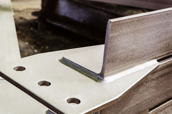
5. 공동 디자인, 맞춤 및 가장자리 준비
좋은 조인트 디자인은 열 입력 요구를 줄이고 품질을 향상시킵니다..
- 랩 조인트 Spot용접과 Sheet용 MIG에 많이 사용; 갇힌 물이나 부식 주머니를 조심하십시오.
- 엉덩이 관절 얇은 시트에는 탁월한 가장자리 준비가 필요합니다. (정사각형, 좁은 틈) 레이저 또는 TIG용. 레이저의 경우 루트 갭은 일반적으로 0–0.5mm입니다.; TIG는 더 많은 것을 견딜 수 있습니다.
- 필렛 용접: 강도와 강성을 위해, 화상을 피하기 위해 목 크기를 제한하십시오.. 일반적인 필렛 레그 1 mm 시트는 ~1~2mm이지만 주의 깊게 제어해야 합니다..
- 가장자리 베벨: 일반적으로 얇은 시트에는 필요하지 않음; 사용하는 경우, 과도한 필러와 열을 피하기 위해 베벨을 얕게 유지하십시오..
- 공차: 레이저 및 FSW용, 맞춤 공차가 엄격합니다. (±0.1mm 이상). 매우 얇은 소재의 MIG/TIG용, 틈 <0.5 mm는 번스루(burn-through)를 방지하기 위해 일반적입니다..
6. 열 입력, 왜곡 제어 및 고정 전략
얇은 시트는 쉽게 휘어집니다. 제어 전략에는 다음이 포함됩니다.:
- 낮은 열 입력: 펄스 용접, 더 높은 이동 속도, GMAW의 단락 전환, 펄스 MIG/TIG.
- 간헐적인 바느질: 응력 완화를 위해 간격이 있는 세그먼트를 용접합니다.; 최종 패스로 공백 메우기.
- 균형 잡힌 용접 순서: 용접 대칭 위치 및 백스텝 기술.
- 강력한 고정 장치 및 압정: 완전 용접 전 클램프 및 스폿 압정으로 움직임 감소.
- 방열판 및 백킹 바: 구리 뒷면은 열을 발산하고 번스루(burn-through)를 방지합니다..
- 사전 굽힘/과도한 제어: 의도적으로 사전 왜곡한 다음 릴리스 후 평평하게 끝나도록 용접합니다..
7. 결함, 근본 원인 및 대책
| 결함 | 증상 | 근본 원인 | 대책 |
| 번쓰루 | 시트에 구멍이 있음, 지역적 용해 | 과도한 열 입력, 느린 여행, 얇은 부분 | 전류/열 감소, 이동 속도를 증가, 백바, 스티치 용접 |
| 다공성 | 구덩이 / 용접 가스 구멍 | 오염물질, 수분, 열악한 차폐 | 깨끗한 표면, 건식 와이어/필러, 가스 적용 범위 개선, 뒷면을 퍼지 |
| 융합 부족 | 융합되지 않은 발가락 또는 뿌리 | 낮은 입열량, 몸 상태가 좋지 않음 | 에너지 증가, 이동 속도를 줄이다, 올바른 관절 준비 |
| 열분해 (뜨겁다/차갑다) | HAZ 또는 용접의 균열 | 높은 구속, 수소, 급속 냉각 | Low-H 소모품, 예열/후열, 피닝 또는 스트레스 해소 |
| 과도한 스패터 | 비드 주위에 튄 자국 (나) | 잘못된 전송 모드 / 가스 | 펄스 또는 단락으로 전환, 가스 혼합을 조정하다 |
| 언더컷 | 용접 토우의 홈 | 과도한 전압 또는 이동 속도 | 전압을 줄이세요, 느린 여행, 토치 각도 조정 |
| 표면 오염 / 변색 | 산화, 불쌍한 외모 | 부적절한 차폐 또는 오염 | 차폐 개선, 용접 전 청소 |
| 스폿 용접 실패 | 얕거나 덩어리가 없음, 제명 | 잘못된 전극력, 현재 또는 시간 | 압착력 및 현재 일정 조정, 전극 교체 |
8. 점검, 테스트 및 품질 보증
시트 용접의 품질 관행:
- 육안검사: 용접 프로파일, 언더컷, 튐, 표면 불연속성.
- 염료침투제 (Pt): 민감한 표면 균열 감지.
- 초음파 (유타): 두꺼운 시트나 다층의 표면 아래 결함을 감지할 수 있습니다..
- 교차 장력 테스트 / 껍질 테스트: 점용접 강도를 검증하는 데 사용됨.
- 기계적 테스트: 인장, 만곡부, 대표쿠폰에 대한 미세경도 테스트 및.
- 치수 제어: 평탄도 및 왜곡 측정; 고정장치로 수정하거나 재작업하세요.
- 프로세스 제어 문서: WPS, 해당 표준에 따른 PQR 및 용접공 자격.
9. 판금 재료 용접을 위한 실용적인 팁
시작하기 전에 — 준비 체크리스트
- 재료 식별 & 성질. 합금 확인 (예를 들어, 304L 대 304), 두께 및 코팅. 알 수 없는 경우, 샘플 및 테스트.
- 조인트를 청소하세요.. 오일/그리스 제거, 흙, 밀 스케일 및 중산화물. 알루미늄의 경우 기계적으로 산화물을 제거하거나 AC TIG 산화물 세척에 의존합니다.. 아연도금용, 가능하다면 용접 부위 바로 옆에서 아연을 벗겨내십시오..
- 핏업 & 압정. 얇은 패널의 경우 25~50mm마다 가용접 사용; 더 작은 간격 (10-25mm) 긴 솔기 또는 얇은 경우, 유연한 부품. 클램프가 부품을 평평하게 고정하고 정렬되었는지 확인하세요..
- 건식 필러 & 소모품. 필러 와이어와 로드를 밀봉/건조하게 유지하십시오.; 사양에 따라 필요한 경우 전극을 굽습니다..
- 열 제어 계획. 백바가 어디에 있는지 식별, 방열판 또는 스티치 용접이 사용됩니다.. 고정 장치 및 열 클램프 준비.
- 연기 제어 & PPE. 아연도금을 위한 국소배기, 놋쇠, 스테인리스; 필요한 경우 호흡기. 눈, 처리에 적합한 손 및 신체 보호.
프로세스 & 매개변수 휴리스틱 (스타터 규칙)
이것이 출발점입니다. 항상 누적을 재현하는 쿠폰을 확인하세요., 코팅 및 클램핑.
GMAW / 나 (얇은 강철 0.8–1.5 mm)
- 철사: 0.8 mm ER70S-6.
- 옮기다: 1.5mm 이하의 단락; 더 높은 품질을 위해 펄스 처리됨.
- 현재의: 60-140A (낮게 시작하다, 조심스럽게 늘리다).
- 전압: 16-22V.
- 이동 속도: 200–600mm/분.
- 실드가스: 75% Ar/25% CO₂ (경제적) 또는 98% Ar/2%O2 (더 나은 젖음).
GTAW / 싸움 (얇은 스테인레스 & 알류미늄)
- 스테인레스 (1.0 mm): DCEN 35–90A; Ar 유량 8~15L/min.
- 알류미늄 (0.8–2.0 mm): 그리고 60~160 그리고; 맥박 & 밸런스 조절에 도움이 됨; 토치 시작 사용 (HF 또는 리프트) 전극을 보호하기 위해.
- 텅스텐: 1.6–2.4mm 란탄화/세륨화(DC용), AC의 경우 thoriated 또는 lanthanated.
저항 점용접 (0.8 + 0.8 mm 연강)
- 전극력: 3-6kN.
- 용접 전류: 7-12 (기계 & 전극 의존적).
- 용접 시간: 200–600ms (주전원 주파수 및 일정에 따라 다름).
- 전극 유지: 정기적으로 얼굴에 옷을 입힌다; 파괴/비파괴 샘플링을 통해 너겟 크기 모니터링.
레이저 용접 (1.0 mm 스테인리스 엉덩이)
- 힘: 1이동 속도에 따라 –4kW.
- 속도: 1얇은 시트의 경우 –5m/min.
- 초점 지점: 0.2–0.6 mm; 탁월한 가장자리 품질과 긴밀한 핏을 보장합니다..
- 백퍼지: 산화 방지를 위한 스테인리스의 경우 아르곤 5~15L/min.
FSW (알루미늄 패널)
- 도구 rpm: 800–2000rpm; 이송 속도 100~500mm/분 (속도와 열의 균형).
- 견고한 백플레이트 사용; 플런지 결함을 방지하기 위해 얇은 시트에 중요한 도구 설계.
왜곡 및 번스루 제어
- 낮은 열 입력 방법을 사용하십시오: 싸움, 펄스 ME, 왜곡이나 시각적 외관이 중요한 경우 레이저 또는 FSW.
- 스티치/스킵 용접: 10~30mm 용접, 10~30mm 건너뛰기, 그런 다음 다시 공백을 메우십시오. 이렇게 하면 국지적인 열 축적이 제한됩니다..
- 균형 순서: 부품과 대체 측면에 대해 대칭으로 용접. 솔기용, 수축을 제어하기 위해 짧은 세그먼트로 백스텝.
- 클램핑 & 역행: 견고한 클램프와 구리 백킹 바는 열을 발산하고 번스루(burn-through)를 방지합니다.; 희생 백킹 시트는 매우 얇은 부품에 효과적입니다..
- 사전 굽힘 및 과잉 보상: 예상된 변형과 반대로 의도적으로 약간 왜곡되어 용접 후 부품이 사양에 맞게 완화됩니다..
- 방열판 사용: 중요 구역 아래의 임시 구리 블록 또는 수냉식 고정 장치는 HAZ 및 변형을 줄입니다..
압정, 고정 및 정렬 팁
- 최소 압정 크기: 부품을 고정할 만큼만 작은 압정을 사용한 다음 전체 용접으로 마무리합니다.. 얇은 시트의 경우 3~6mm의 고정 길이를 사용하세요..
- 감사합니다 주문하세요: 간격을 최소화하기 위해 압정을 놓는다; 과도한 점착은 과도한 국소 가열과 같으므로 과도하게 부착하지 마십시오..
- 설비 가열: 부품이 자주 왜곡되는 경우, 열 흐름을 제어하기 위해 적극적으로 수냉식 고정 장치 또는 세라믹 패드를 고려하십시오..
- 퀵 체인지 팔레트: 생산을 위해, 반복 가능한 핏업을 보장하고 사이클 시간을 최소화하는 고정 장치 설계.
소모품, 압형 & 유지
- 전극 & 그 사람: MIG/TIG의 경우 접촉 팁과 노즐을 깨끗하게 유지하십시오.; 마모된 팁 교체 - 마모된 팁으로 인해 불규칙한 와이어 공급 및 일관되지 않은 아크가 발생합니다..
- 와이어 선택: 와이어 화학 물질을 모재 금속과 일치시키고 마감 처리합니다.; 건조한 스풀을 유지.
- 전극드레싱 (RSW): 얼굴 기하학을 교정하기 위해 구리 전극을 입으십시오.; 마모된 전극은 접촉을 줄이고 전류 요구 사항을 증가시킵니다..
- 토치 각도 & 튀어나온: MIG에 대해 일관된 스틱아웃 유지 (~10~20mm 일반) 그리고 적절한 토치 각도 (10–20 °) 침투 및 비드 모양 제어.
10. 프로세스 선택 매트릭스: 언제 어떤 방법을 사용해야 하는가
| 용접 과정 | 시트 두께 범위 | 재료 적합성 | 주요 장점 | 일반적인 응용 분야 |
|---|---|---|---|---|
| GMAW / 나 | 0.8 – 12 mm | 탄소강, 스테인레스 스틸, 알류미늄 | 빠른, 쉬운 자동화, 적당한 열 입력 | 자동차 패널, 산업용 인클로저, 구조 프레임 |
| GTAW / 싸움 | 0.5 – 6 mm | 스테인레스 스틸, 알류미늄, 구리 합금 | 정밀한, 깨끗한 용접, 최소한의 튀김 | 항공우주, 고품질 어셈블리, 장식 패널 |
| 저항 점용접 (RSW) | 0.5 – 3 mm | 탄소강, 스테인레스 스틸 | 매우 빠릅니다, 반복 가능, 최소한의 왜곡 | 자동차 차체 패널, 가전제품 제조 |
| 마찰 저어 용접 (FSW) | 1 – 12 mm | 알류미늄, 구리, 마그네슘 | 고체 용접, 고강도, 낮은 왜곡 | 항공기 동체 패널, 배 선체, 항공우주 부품 |
| 레이저 빔 용접 (LBW) & 잡종 | 0.3 – 6 mm | 스테인레스 스틸, 알류미늄, 고강도 강철 | 깊은 침투, 낮은 열 입력, 고속 | 자동차, 의료기기, 정밀 어셈블리 |
| 플라즈마 아크 용접 (PAW) | 0.5 – 6 mm | 스테인레스 스틸, 니켈 합금, 티탄 | 고품질, 제어된 아크, 좁은 HAZ | 항공우주, 핵무기, 고성능 구성 요소 |
| 산소 연료, 브레이징, 납땜 | 0.1 – 3 mm | 구리, 놋쇠, 얇은 강철, 코팅 된 금속 | 저열, 비 유사 금속 결합, 최소한의 왜곡 | 공조, 전자 제품, 장식 아이템 |
11. 결론
판금을 성공적으로 용접하려면 재료에 맞는 공정 능력이 필요합니다., 공동 및 생산 요구 사항.
주요 결정은 다음과 같습니다. 열 관리, 조인트 핏업, 그리고 프로세스 제어. 간단한 랩 조인트를 사용한 대용량용, 저항 점용접 가장 경제적이다.
미용 솔기 및 수리 작업용, 싸움 선호된다. 고급의, 저왜곡 생산, 원자 램프 또는 FSW 올바른 선택이 될 수도 있다. 항상 대표쿠폰으로 검증하세요, 용접 변수 제어, 검사 및 QA 실시.
자주 묻는 질문
내가 용접할 수 있는 가장 얇은 시트는 무엇입니까?
적절한 기술로 (원자 램프, TIG 또는 펄스 MIG), 시트까지 0.3–0.5 mm 번스루(burn-through) 없이 용접 가능. 저항 점용접은 시트당 ~0.6mm의 랩 조인트에 적합합니다..
용접판 조립의 왜곡을 어떻게 줄일 수 있나요??
열 입력 최소화 (더 높은 이동 속도, 펄스 모드), 균형 잡힌 용접 순서 사용, 강력한 고정 및 스티치 용접. 백바 및 클램프를 사용하여 방열판 역할을 함.
이종 금속을 용접할 수 있나요? (예를 들어, 강철에서 알루미늄으로)?
강철과 알루미늄을 직접 융합 용접하는 것은 부서지기 쉬운 금속간 화합물로 인해 문제가 있습니다.. 선호하는 옵션은 다음과 같습니다. 브레이징, 기계적 고정, 또는 고체 접합 (마찰 용접 또는 마찰 교반 기술) 전환 레이어 포함.
아연 도금과 같은 코팅은 용접을 방지합니까??
코팅으로 인해 용접이 복잡해짐: 아연은 기화하여 다공성과 독성 연기를 유발할 수 있습니다.. 용접 부위의 코팅을 제거하거나 코팅에 내성이 있는 공정을 사용하십시오. (추출이 가능한 레이저) 항상 연기 추출 장치와 PPE를 사용하십시오..
융합 용접 대신 FSW를 선택해야 하는 경우는 언제입니까??
사용 FSW 왜곡을 최소화해야 하는 알루미늄 합금용, 우수한 기계적 특성, 그리고 필러 없음. FSW는 조인트를 따라 회전 도구에 대한 접근이 필요합니다..

