

Casting remains one of the most economical and versatile manufacturing processes for producing complex metal components.
Whether using sand casting, investment casting, shell mold casting, V-process casting, or lost foam casting, foundries strive to achieve castings with high dimensional accuracy, sound internal quality, and excellent surface finish.
However, even in modern foundries equipped with advanced melting furnaces, simulation software, and automated molding lines, casting defects cannot be completely eliminated.
Defects may originate from improper gating and riser design, unsuitable molding materials, inadequate melting practices, poor pouring control, or insufficient process management.
If not identified and corrected promptly, these defects can lead to increased scrap rates, costly rework, delayed production schedules, and reduced product reliability.
Successful defect prevention requires understanding the interaction among molten metal behavior, mold characteristics, solidification dynamics, and process parameters rather than addressing each problem in isolation.
1. Misrun
Defect Characteristics
A misrun is a casting defect in which molten metal fails to completely fill the mold cavity before solidification, resulting in localized missing sections of the casting.
Unlike shrinkage defects, a misrun occurs during the mold-filling stage, when the advancing metal front loses fluidity and freezes before reaching the extremities of the cavity.
Misruns are most commonly observed in:
- Thin-wall sections with high cooling rates
- Long flow paths far from the ingate
- Narrow ribs, fins, and bosses
- Upper portions of vertically oriented castings
- Areas with abrupt changes in wall thickness
The unfilled edges are typically smooth, rounded, and clean, with no evidence of adhered molding sand.
This characteristic distinguishes a misrun from defects such as cold shut, where two partially solidified metal streams meet but fail to fuse metallurgically, leaving a visible seam or lap line.
In severe cases, entire features of the casting may be absent, rendering the component unusable without repair or replacement.
Root Causes
A misrun is rarely caused by a single factor. Instead, it usually results from the combined effects of insufficient metal fluidity, excessive heat loss, poor gating design, inadequate mold venting, and unfavorable alloy characteristics.
Inappropriate Pouring Parameters
The most common cause is a mismatch between pouring temperature and pouring speed.
When the pouring temperature is too low, the molten metal loses superheat rapidly upon entering the mold.
If the pouring rate is also too slow—or the pouring operation is interrupted—the leading edge of the metal stream begins to solidify before the cavity is completely filled.
Typical process-related causes include:
- Low pouring temperature
- Excessively slow pouring rate
- Interrupted or inconsistent pouring
- Excessive heat loss during ladle transfer
These conditions significantly reduce the effective filling distance of the molten metal.
Undersized or Poorly Designed Gating System
The gating system controls both the flow velocity and the volume of molten metal entering the mold.
If the runner or ingate cross-sectional area is too small, excessive flow resistance develops, restricting metal flow and increasing filling time.
Long or tortuous flow paths further reduce metal temperature before the cavity is filled.
Other design issues include:
- Improper gating ratio
- Excessive pressure loss
- Unbalanced runner distribution
- Inadequate ingate locations for thin-wall regions
Modern foundries frequently use casting simulation software to optimize gating geometry and predict potential misrun locations before production.
Poor Alloy Fluidity
The fluidity of molten metal depends not only on temperature but also on alloy chemistry.
For ferrous castings, excessively low carbon equivalent (CE)—caused by insufficient carbon and silicon—reduces the fluidity of molten iron, making it more difficult to fill complex or thin-wall cavities.
Similarly, excessive oxidation, high inclusion content, or improper alloy modification can impair flow characteristics and increase the likelihood of premature solidification.
Excessive Mold Backpressure
During pouring, gases generated by the molding materials must escape rapidly through the mold.
If the molding sand contains:
- Excessive moisture
- High coal dust content
- Large amounts of organic binders
- Excessive clay
gas evolution increases significantly. When combined with poor sand permeability or inadequate venting, trapped gases create backpressure that opposes the advancing metal front, slowing mold filling and increasing the risk of a misrun.
This problem is particularly common in large castings or molds with deep cavity sections.
Insufficient Metallostatic Head
Molten metal is driven through the cavity by metallostatic pressure, which is primarily determined by the height of the molten metal column above the cavity.
If the upper flask (cope) is too shallow or the sprue height is insufficient, the available static pressure may not be adequate to push molten metal into distant, elevated, or thin-wall regions of the mold before solidification occurs.
This issue is especially critical for:
- Large castings
- Vertically oriented molds
- Thin-wall investment castings
- Complex pump and valve bodies
Engineering Solutions
Preventing misruns requires a systematic optimization of the pouring process, gating design, alloy composition, and mold characteristics.
Recommended engineering practices include:
Optimize Pouring Parameters
Maintain the pouring temperature within the recommended range for the alloy while avoiding excessive superheat that could increase oxidation or shrinkage.
A controlled pouring profile is generally recommended:
- Slow start to minimize turbulence
- Steady and rapid filling during the main pouring stage
- Controlled finish to reduce slag entrainment
Continuous pouring without interruption is essential to maintain metal fluidity throughout cavity filling.
Improve Gating System Design
Recalculate the cross-sectional areas of the sprue, runners, and ingates to ensure adequate metal flow.
Engineering improvements may include:
- Enlarging runner and ingate sections
- Optimizing gating ratios
- Reducing flow resistance
- Shortening filling distance
- Adding additional ingates for complex geometries
- Using casting simulation to verify filling behavior
Proper gating design not only prevents misruns but also improves yield and reduces turbulence-related defects.
Enhance Alloy Fluidity
Adjust furnace charge composition to maintain the specified carbon equivalent (CE) or alloy chemistry.
For gray and ductile iron, slightly increasing carbon and silicon within specification limits can significantly improve molten metal fluidity without compromising mechanical properties.
Additional measures include:
- Proper inoculation treatment
- Inclusion control
- Slag removal before pouring
- Maintaining clean molten metal
Optimize Molding Sand Properties
Improve mold permeability to facilitate gas evacuation.
Effective measures include:
- Reducing excessive coal dust additions
- Controlling moisture content
- Optimizing clay and binder levels
- Increasing permeability through appropriate sand grading
- Adding vent holes or auxiliary venting channels in critical areas
Good mold ventilation minimizes gas backpressure and promotes smooth mold filling.
Increase Metallostatic Pressure
Where practical, increase the effective metal head by:
- Using a taller sprue
- Increasing cope height
- Raising pouring basin elevation
- Adopting bottom-gated or stepped gating systems
Bottom gating is particularly effective because it provides more stable filling, reduces turbulence, minimizes gas entrapment, and improves the filling of thin-wall sections.
2. Short Pour
Defect Characteristics
A short pour is a casting defect in which the mold cavity is not completely filled because an insufficient volume of molten metal is poured into the mold.
Unlike a misrun, which is primarily caused by inadequate metal fluidity or premature solidification during filling, a short pour occurs when the pouring process is terminated before enough molten metal enters the cavity.
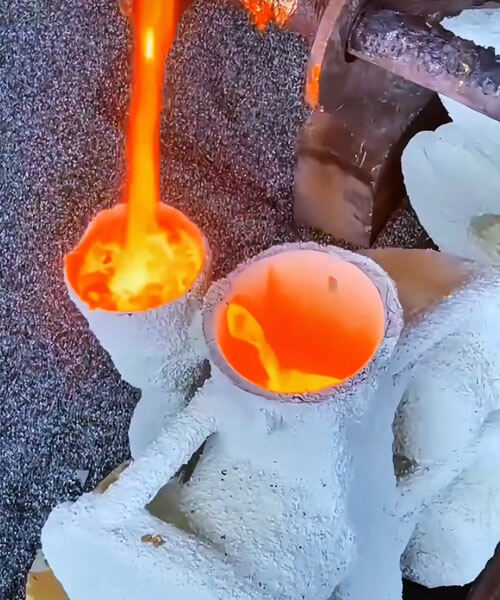
The defect typically appears as:
- An incomplete upper section of the casting
- Missing bosses, flanges, or top surfaces
- A relatively flat metal level inside the casting
- Slightly rounded edges at the unfilled boundary
- The molten metal level in the sprue being approximately flush with the metal level inside the casting cavity
Since the molten metal does not reach the designed fill volume, the defect usually affects the highest regions of the mold cavity, where complete filling depends on sufficient pouring volume.
From a quality control perspective, short pour is considered an operational defect rather than a metallurgical or mold-filling defect, as the available molten metal is simply inadequate to produce a complete casting.
Root Causes
| Cause Category | Specific Factor | Mechanism |
| Weight miscalculation | Operators miscalculate required metal weight | Insufficient molten metal in the ladle to fill casting + gating + risers |
| False fill illusion | Narrow gating channels with fast pouring | Metal overflows from pouring cup before cavity is full; operator misjudges filling state |
| Ladle capacity | Insufficient surplus capacity | No extra metal available to compensate for variations |
Engineering Solutions
Preventing short pour relies primarily on accurate process planning and standardized pouring practices.
Accurately Calculate Pouring Weight
Before production, determine the total molten metal requirement by considering all elements of the casting system, including:
- Finished casting weight
- Gating system
- Risers
- Overflow sections
- Process losses
- Safety allowance
In production, the ladle capacity should typically include an additional 10–15% metal reserve to compensate for transfer losses, slag removal, and operational variations.
Computer-aided casting simulation and digital process planning can further improve pouring weight accuracy for complex components.
Optimize Pouring Operation
For molds with relatively narrow gating systems, the initial pouring rate should be carefully controlled to prevent premature overflow from the pouring cup.
A stable pouring sequence helps maintain continuous mold filling while allowing operators to monitor the actual filling condition more accurately.
Where possible, automated pouring systems can maintain consistent pouring velocity and significantly reduce operator-related errors.
Standardize Mold Filling Verification
Operators should never judge mold filling solely by observing the pouring cup.
Instead, cavity filling should be confirmed by monitoring:
- Metal level in risers
- Overflow indicators
- Observation ports (where applicable)
- Established pouring time standards
- Automated level monitoring systems for high-volume production
Standard operating procedures (SOPs) and regular operator training are essential to minimize premature termination of pouring operations.
3. Casting Mechanical Damage
Defect Characteristics
Casting mechanical damage refers to physical damage that occurs after the casting has solidified, rather than defects formed during mold filling or solidification.
Typical manifestations include chipped edges, fractured ribs, broken bosses, cracked flanges, missing corners, and localized deformation.
Although the casting itself may be metallurgically sound, mechanical damage can compromise dimensional accuracy, structural integrity, and aesthetic quality, often leading to costly repairs or complete rejection.
Unlike shrinkage cavities, cracks, or misruns, mechanical damage is characterized by fresh fracture surfaces with sharp edges, usually free from oxidation or casting skin.
The damaged areas often expose clean metallic surfaces, indicating that the failure occurred during post-casting operations.
The most vulnerable locations include:
- Thin ribs and webs
- Small bosses and mounting lugs
- Sharp corners and protruding features
- Long cantilever sections
- Flanges and thin-wall edges
Mechanical damage most frequently occurs during:
- Shakeout
- Fettling and cleaning
- Tumbling (barrel finishing)
- Riser and gate removal
- Material handling
- Transportation and storage
Because these defects originate after casting solidification, they are largely preventable through proper equipment selection, tooling design, and standardized operating procedures.
Root Causes
| Cause Category | Specific Factor | Mechanism |
| Shakeout | Violent impact during shakeout | Excessive force causes fracture of weak structures |
| Handling | Collision during transportation | Impact damage from dropping or bumping |
| Barrel finishing | Overloading or unreasonable part matching | Mutual impact and fracture of thin-wall sections |
| Riser design | Oversized riser neck cross-section | Excessive force required for removal; no knock-off groove |
| Riser removal | Incorrect striking direction | Vertical striking pulls and tears the casting body |
Engineering Solutions
Preventing casting mechanical damage requires optimization of handling equipment, riser design, cleaning operations, and standardized work procedures.
Adopt Controlled Shakeout and Handling Practices
Use vibration shakeout equipment with adjustable frequency and amplitude to match the casting size and material.
Additional recommendations include:
- Allow sufficient cooling before shakeout.
- Minimize drop heights during transfer.
- Use lifting fixtures designed for the casting geometry.
- Avoid direct collision between castings.
- Store castings on padded or separated pallets where appropriate.
These measures significantly reduce impact loads on fragile features.
Standardize Barrel Finishing Operations
Barrel finishing parameters should be selected according to casting geometry and material.
Best practices include:
- Limiting barrel loading volume to prevent excessive part movement.
- Separating large and small castings.
- Using ceramic, rubber, or plastic protective media for delicate components.
- Optimizing barrel speed and processing time.
- Inspecting castings periodically during long tumbling cycles.
For highly complex or thin-wall components, vibratory finishing or shot blasting may be preferable to conventional tumbling.
Optimize Riser Neck Design
Proper riser design greatly simplifies subsequent removal.
Recommended engineering measures include:
- Designing riser necks with reduced cross-sections.
- Incorporating dedicated knock-off grooves at the riser root.
- Ensuring the riser neck thickness is smaller than the adjacent casting wall.
- Maintaining smooth stress transitions to prevent unintended cracking.
Modern casting simulation software can optimize riser dimensions while maintaining adequate feeding performance.
Improve Gate and Riser Removal Procedures
Riser removal should follow standardized operating procedures to minimize impact on the casting.
Recommended methods include:
- Apply impact loads tangentially rather than perpendicular to the casting surface.
- Use hydraulic presses for controlled separation where feasible.
- Employ band saws or abrasive cutting for large risers.
- Use oxy-fuel or plasma cutting for heavy steel castings when appropriate.
- Avoid excessive hammering, particularly on precision or thin-wall castings.
These techniques reduce localized stresses and preserve casting integrity.
4. Burn-On Sand and Surface Roughness
Defect Characteristics
Burn-on sand and surface roughness are two of the most common casting surface defects, both of which negatively affect the appearance, dimensional accuracy, machining efficiency, and overall quality of cast components.
Burn-on sand (also referred to as sand burn-on or metal penetration
By contrast, surface roughness describes an uneven, irregular casting surface that remains after the adhered sand has been removed
Typical manifestations include:
- Strongly adhered sand particles
- Rough or irregular casting skin
- Localized pitting
- Metal penetration between sand grains
- Increased machining allowance
- Poor coating or painting performance
- Reduced aesthetic quality
These defects are especially undesirable for pump bodies, valve components, precision machinery parts, and decorative castings, where surface finish is an important quality requirement.
Root Causes
Burn-on sand and surface roughness generally result from the combined effects of molding material properties, pouring conditions, and mold preparation quality.
The fundamental mechanism is excessive interaction between the molten metal and the mold surface.
Coarse Sand Grain Size and Low Mold Hardness
The grain size of the molding sand directly influences the quality of the casting surface.
When excessively coarse sand is used, larger voids exist between adjacent sand grains.
Under the pressure of molten metal, liquid metal can penetrate these gaps and solidify around the sand particles, producing severe metal penetration and burn-on defects.
Similarly, insufficient mold compaction or inadequate mold hardness allows sand grains to move or separate during pouring, increasing the likelihood of surface erosion and roughness.
Excessive Molding Sand Moisture
Moisture content plays a critical role in determining mold strength and compactability.
When the moisture content is too high:
- Mold density becomes non-uniform.
- Surface hardness decreases.
- Steam generation increases during pouring.
- Surface erosion becomes more likely.
Excessive moisture also reduces the mold’s resistance to molten metal pressure, promoting metal penetration and deterioration of the casting surface.
Aggressive Pouring Conditions
Pouring parameters significantly influence the interaction between molten metal and the mold.
Conditions that increase the risk of burn-on include:
- Excessively high pouring temperature
- High metallostatic pressure
- Excessive pouring velocity
- Severe turbulence at the ingate
High-temperature molten metal possesses greater fluidity and lower viscosity, allowing it to infiltrate the spaces between sand grains more easily.
At the same time, turbulent metal flow mechanically erodes the mold surface, resulting in localized surface damage and rough casting skin.
Insufficient Coal Dust or Carbonaceous Additives
In green sand casting, coal dust serves an important protective function.
During pouring, coal dust thermally decomposes to generate reducing gases and a thin bright carbon film
If the coal dust content is insufficient, the protective carbon film cannot form continuously, allowing molten metal to penetrate the mold surface and adhere to the sand.
Improper Pattern Plate Temperature
Pattern plate temperature is often overlooked but has a significant influence on mold surface quality.
If the pattern plate is excessively hot:
- Moisture near the mold surface evaporates rapidly.
- Surface sand dries out.
- Mold strength decreases.
- Surface cracking becomes more likely.
Conversely, if the pattern plate is too cold, moist sand tends to adhere to the pattern during withdrawal, causing localized tearing or peeling of the mold surface.
These damaged areas become susceptible to erosion during pouring, ultimately producing rough casting surfaces.
Engineering Solutions
Effective prevention requires simultaneous optimization of molding materials, pouring practice, and mold preparation.
Optimize Sand Properties
Select molding sand with an appropriate grain size while maintaining sufficient permeability.
Recommended measures include:
- Use finer base sand where surface finish is critical.
- Maintain a balanced sand grain distribution.
- Increase mold compaction to reduce surface porosity.
- Monitor mold hardness consistently throughout production.
A dense, uniform mold surface significantly reduces the likelihood of metal penetration.
Maintain Proper Carbonaceous Additives
Maintain a stable and effective concentration of coal dust or other carbonaceous additives within the molding sand.
During pouring, these materials generate a continuous bright carbon layer that:
- Prevents direct metal-sand contact
- Reduces metal penetration
- Improves casting surface finish
- Facilitates shakeout and cleaning
Regular sand system analysis should be conducted to ensure additive concentrations remain within the specified process range.
Control Molding Sand Moisture
Moisture should be maintained within the optimum range specified for the molding process.
For conventional gray iron green sand systems, the recommended moisture content is typically:
3.0–4.0%
Maintaining stable moisture improves:
- Mold strength
- Surface hardness
- Compaction consistency
- Gas permeability
Automated sand preparation systems are widely used in modern foundries to ensure consistent moisture control.
Optimize Pouring Parameters
The gating system should be designed to minimize turbulence and direct metal impingement on mold surfaces.
Recommended engineering practices include:
- Reduce pouring velocity where feasible.
- Optimize gating ratios.
- Lower pouring temperature to the minimum value that still ensures complete mold filling.
- Reduce excessive metallostatic pressure.
- Employ bottom-gating systems for sensitive castings.
Stable filling conditions significantly reduce both mold erosion and metal penetration.
Maintain Appropriate Pattern Plate Temperature
Pattern temperature should be carefully controlled throughout the molding process.
As a general guideline, the pattern plate temperature should remain slightly higher than the molding sand temperature, allowing:
- Easy pattern withdrawal
- Uniform mold surface strength
- Reduced sand adhesion
- Prevention of excessive surface drying
Consistent pattern temperature contributes directly to improved mold integrity and better casting surface quality.
5. Sand Inclusions (Sand Holes)
Defect Characteristics
Sand inclusions, commonly referred to as sand holes, are casting defects in which molding sand particles become entrapped within the molten metal and remain embedded in the casting after solidification.
Depending on where the sand becomes trapped, the defect may appear either on the casting surface or deep within the interior.
Surface sand inclusions are generally visible after shot blasting or machining, whereas internal sand inclusions are often concealed and can only be detected through radiographic testing (RT), ultrasonic testing (UT), computed tomography (CT), or destructive sectioning.
Because they interrupt the continuity of the metal matrix, internal sand inclusions are particularly detrimental to pressure-retaining components, where they may become leakage paths or initiate fatigue cracks under cyclic loading.
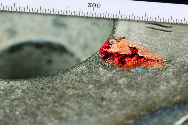
Typical characteristics include:
- Irregular cavities partially or completely filled with molding sand
- Rough, angular defect surfaces
- Embedded silica particles or mold material
- Localized porosity associated with entrapped sand
- Reduced pressure tightness and mechanical strength
- Poor machinability due to tool wear caused by hard sand particles
Sand inclusions are among the most frequently encountered casting defects in sand casting and remain a major cause of rejection for critical components such as valve bodies, pump casings, hydraulic manifolds, compressor housings, and pipe fittings.
Root Causes
Sand inclusions originate when molding sand is detached from the mold surface or introduced into the mold cavity, where it is subsequently engulfed by the flowing molten metal.
Their formation is typically associated with deficiencies in mold quality, pattern design, mold handling, or gating system performance.
| Cause Category | Specific Factor | Mechanism |
| Mold surface strength | Insufficient binder content | Surface sand grains easily washed off by molten metal |
| Pattern design | Sharp corners without fillets; insufficient draft angle | Causes sand tearing during pattern withdrawal |
| Mold handling | Damaged molds closed without repair | Damaged areas become sand sources |
| Storage | Molds stored too long before pouring | Surface dries out and loses strength |
| Mold closing | Foreign sand entry; floating sand not cleaned | Sand enters cavity; uncovered pouring cups allow loose sand to fall in |
Engineering Solutions
Reducing sand inclusions requires comprehensive control of molding materials, pattern quality, mold preparation, and molten metal flow.
Improve Molding Sand Quality
Optimize the molding sand formulation to ensure adequate surface strength throughout production.
Recommended measures include:
- Maintain appropriate clay or binder content.
- Regularly replenish fresh sand to stabilize sand system properties.
- Optimize sand mixing time and moisture control.
- Improve green compression strength and wet tensile strength.
- Monitor sand properties through routine laboratory testing.
A stronger mold surface is significantly more resistant to erosion during pouring.
Optimize Pattern Design and Mold Repair
High-quality pattern design minimizes mold damage during pattern withdrawal.
Engineering recommendations include:
- Incorporate appropriate draft angles.
- Design generous fillets at sharp corners.
- Maintain smooth pattern surfaces.
- Repair all damaged mold areas before assembly.
- Ensure repaired sections are properly dried and compacted.
Careful mold preparation reduces the generation of loose sand before pouring.
Minimize Mold Storage Time
Whenever possible, molds should be poured shortly after preparation.
If temporary storage is unavoidable:
- Protect molds from excessive drying.
- Control ambient humidity.
- Prevent direct airflow over mold surfaces.
- Inspect surface integrity before pouring.
Maintaining mold strength throughout storage helps prevent surface erosion during metal filling.
Remove Loose Sand Before Mold Closing
Thorough cavity cleaning is essential before mold assembly.
Best practices include:
- Blow the cavity clean using compressed air.
- Vacuum loose sand from deep pockets.
- Inspect repaired areas carefully.
- Immediately cover the pouring basin after mold closing to prevent contamination from airborne sand or debris.
Strict housekeeping procedures substantially reduce the risk of foreign material entering the mold.
Optimize the Gating System and Install Ceramic Filters
A well-designed gating system minimizes turbulence and mold erosion.
Recommended improvements include:
- Reduce metal velocity at critical locations.
- Eliminate direct impingement on mold walls.
- Optimize runner and ingate geometry.
- Promote smooth, laminar mold filling.
For high-quality castings, ceramic foam filters should be installed within the gating system. These filters effectively capture:
- Detached sand particles
- Slag
- Oxide films
- Non-metallic inclusions
before they enter the casting cavity, significantly improving internal cleanliness and reducing scrap rates.
6. Veining and Mold Swelling
Defect Characteristics
Veining (also known as flash, finning, or parting-line flash) and mold swelling are two common casting defects associated with mold deformation under the combined effects of molten metal pressure and elevated temperature.
Although both defects originate from insufficient mold rigidity or strength, they differ in appearance and formation mechanism.
Veining is characterized by thin, irregular sheet-like metal projections extending outward from the casting surface.
These protrusions are generally perpendicular to the surface and most frequently occur along the parting line, core joints, or mold cracks.
Because the molten metal penetrates narrow openings created by mold separation or thermal expansion, the resulting flash is typically thin, sharp, and uneven in thickness.
Mold swelling, in contrast, appears as localized bulges or rounded protrusions on either the internal or external surfaces of the casting.
Rather than forming thin fins, swelling results from plastic deformation or outward displacement of the mold wall under metallostatic pressure, producing oversized or irregularly shaped sections on the finished casting.
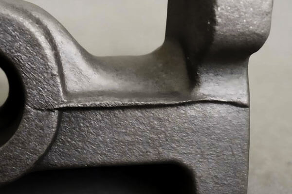
Typical characteristics include:
- Thin metallic fins along parting surfaces (veining/flash)
- Localized bulging or nodular projections (mold swelling)
- Increased casting dimensions beyond design tolerances
- Excessive fettling and grinding requirements
- Reduced dimensional accuracy
- Higher machining costs due to excess material removal
While these defects can often be removed during finishing, they increase production costs and may compromise the dimensional precision required for machined or assembled components.
Root Causes
Veining and mold swelling generally result from a combination of insufficient mold strength, inadequate compaction, excessive moisture, and excessive pressure exerted by molten metal during pouring.
| Cause Category | Specific Factor | Mechanism |
| Mold compaction | Insufficient or uneven mold compaction | Local loose sand areas deform and expand under metal static pressure |
| Molding sand | Insufficient face sand strength or high moisture | High moisture reduces high-temperature wet strength; surface layer yields under heat/pressure |
| Pouring conditions | Excessive metallostatic pressure and pouring speed | Fast metal filling causes sharp cavity pressure rise; pushes sand wall outward |
Engineering Solutions
Preventing veining and mold swelling requires improvements in mold preparation, sand quality, gating design, and structural reinforcement.
Improve Mold Compaction Quality
Optimize molding parameters to achieve consistent and uniform compaction throughout the mold.
Recommended practices include:
- Increase overall mold hardness.
- Eliminate localized loose sand regions.
- Maintain consistent compaction pressure.
- Regularly verify mold hardness using standardized testing methods.
- Ensure proper flask alignment before mold closing.
Uniform mold density significantly improves resistance to deformation during pouring.
Optimize Molding Sand Properties
Enhance the high-temperature performance of the molding sand by controlling both composition and moisture.
Key measures include:
- Adjust binder and clay content appropriately.
- Maintain moisture within the specified process range.
- Improve high-temperature wet tensile strength.
- Optimize sand mixing time and additive distribution.
- Regularly monitor sand system properties through laboratory testing.
A stronger mold surface better withstands thermal and mechanical loading.
Optimize Gating and Pouring Conditions
Reducing excessive cavity pressure is one of the most effective methods for minimizing mold deformation.
Engineering improvements include:
- Reduce pouring velocity where practical.
- Optimize gating ratios.
- Lower excessive metallostatic head.
- Design smoother metal flow paths to reduce turbulence.
- Employ bottom-gating systems where appropriate to stabilize cavity filling.
Proper gating design distributes pressure more uniformly and minimizes localized mold loading.
Reinforce Critical Mold Sections
For large, heavy, or thick-wall castings, additional structural support should be incorporated into the mold system.
Recommended reinforcement methods include:
- Strengthening vulnerable mold sections with reinforcing bars or support structures.
- Increasing flask rigidity.
- Using chills where appropriate to accelerate local solidification and reduce pressure duration.
- Reinforcing large cores with internal supports or chaplets when necessary.
These measures help maintain cavity geometry throughout pouring and solidification.
7. Mold Lift (Flask Lifting) and Runout
Defect Characteristics
Mold lift, also known as flask lifting or cope lift, is a serious casting defect in which the upper mold (cope) is forced upward during pouring, creating a gap at the parting plane between the cope and drag.
Molten metal then penetrates this gap, producing excessive flash and causing the casting to exceed its intended dimensions.
In severe cases, the separation becomes large enough for molten metal to escape from the mold cavity. This phenomenon is known as runout (or metal leakage).
Runout is one of the most hazardous defects in foundry production because it not only results in complete casting failure but also poses significant safety risks to personnel and equipment due to the uncontrolled release of high-temperature molten metal.
Typical characteristics include:
- Large, continuous flash along the parting line
- Increased casting thickness or oversized dimensions
- Visible separation between cope and drag
- Molten metal leakage from the mold
- Incomplete filling caused by loss of molten metal
- Severe surface oxidation and contamination near leakage areas
Once runout occurs, the remaining molten metal inside the cavity may be insufficient to complete filling, often leading to secondary defects such as misruns, short pours, shrinkage cavities, and dimensional distortion.
Root Causes
Mold lift and runout occur when the upward forces generated during pouring exceed the restraining force that holds the mold halves together.
Their occurrence is generally associated with deficiencies in mold clamping, pouring practice, or tooling accuracy.
| Cause Category | Specific Factor | Mechanism |
| Clamping/weighting | Insufficient clamping or weighting | Loose flask locking; insufficient press weights; premature removal of weights before solidification |
| Pouring impact | Excessive pouring speed | Large upward dynamic force exceeds holding force of press weights |
| Pattern plate | Warped pattern plate | Poor fit of the parting plane; leaves gaps for metal leakage |
Corrective Solutions
- Proper weighting: Calculate required press weight according to casting projected area and metallostatic head; remove press weights only after the casting is fully solidified; use flask clamps for auxiliary locking.
- Reduce pouring impact: Lower the ladle pouring position; reduce pouring speed to decrease upward impact force on the upper mold.
- Maintain pattern plates: Regularly inspect the flatness of pattern plates; repair or replace warped and deformed pattern plates in time.
- Multi-point weighting: For large castings, adopt multi-point uniform weighting to avoid local mold lifting caused by unbalanced pressure.
- Flask design: Ensure flask design provides adequate rigidity and clamping points for the specific casting weight and pressure.
8. Summary Table: Defects and Solutions
| Defect | Primary Root Causes | Key Solutions |
| Misrun | Low pouring temperature; poor fluidity; insufficient metallostatic head | Increase pouring temperature; optimize gating; improve alloy fluidity; increase flask height |
| Short Pour | Insufficient metal weight; false fill illusion | Accurate weight calculation; standardize pouring procedure; 10-15% surplus metal |
| Mechanical Damage | Violent shakeout; incorrect riser removal; poor handling | Gentle handling; proper riser design; correct removal technique; optimized finishing |
| Burn-On/Roughness | Coarse sand; low mold hardness; high pouring temp | Finer sand; better compaction; optimized coal dust; controlled moisture; improved gating |
Sand Inclusions |
Low mold strength; pattern defects; foreign sand | Optimized sand formulation; improved pattern quality; cavity cleaning; ceramic filters |
| Veining/Swelling | Poor compaction; weak sand; excessive pressure | Better compaction; improved sand strength; optimized gating; local reinforcement |
| Mold Lift/Runout | Insufficient weighting; excessive impact; warped pattern | Proper weighting; reduced impact; pattern maintenance; multi-point weighting |
9. Conclusion
The prevention and control of casting defects is a systematic engineering task that cannot be solved by adjusting a single process parameter.
The seven common defects analyzed above cover all key links of sand casting production: pattern design, molding sand preparation, gating design, pouring operation and post-casting cleaning.
Most defects can be effectively avoided through forward process optimization, standardized on-site operation and real-time process parameter monitoring, rather than post-remediation after scrapping occurs.
Key Takeaways
- Defects are interconnected: Addressing one defect may affect others; a holistic approach is essential.
- Prevention is better than cure: Forward optimization and process control are more effective than post-inspection sorting.
- Data-driven improvement: Track defect rates, analyze trends, and implement continuous improvement cycles.
- Operator training: Skilled operators who understand defect mechanisms are critical to quality.
- Process standardization: Consistent, documented procedures reduce variation and prevent recurrence.
Foundries should establish a closed-loop defect analysis mechanism: classify and count defect types, trace back to root causes from appearance characteristics, and verify improvement effects through process tests.
Continuous quality optimization based on data will not only reduce rejection rate and production cost, but also lay a solid foundation for the production of high-grade and high-value-added castings.
FAQs
What is the difference between misrun and short pour?
Misrun is caused by premature solidification before cavity filling is complete (fluidity/thermal issue).
Short pour is caused by insufficient total metal volume (weight/quantity issue). Misrun affects specific thin sections; short pour affects the entire top section.
Why do sand inclusions occur even with good molding sand?
Sand inclusions can result from pattern defects (sharp corners, insufficient draft), damaged molds closed without repair, foreign sand from cleaning, or sand washed from the surface during pouring.
Even good sand can’t compensate for these issues.
How can I distinguish between sand inclusion and slag inclusion?
Sand inclusions contain angular sand grains and are typically brown/grey.
Slag inclusions are glassy, darker, and often have a different metallic composition (oxides, silicates).
Sand inclusions tend to be irregular; slag inclusions often appear as smooth, glassy particles.
What is the most effective way to prevent burn-on sand?
A combination of: using finer sand, increasing mold hardness, optimizing coal dust content (to form a bright carbon layer), controlling moisture, and reducing pouring temperature.
No single measure is fully effective; they work together.

