Sinker electrical discharge machining, also referred to as ram EDM, die-sinking EDM or cavity EDM, is one of the most precise and irreplaceable non-traditional manufacturing processes in modern precision engineering.
Unlike conventional milling and turning that remove material through mechanical cutting force, sinker EDM erodes electrically conductive workpieces through controlled, repetitive electrical sparks, with no physical contact between the tool and the part.
This fundamental difference allows it to produce complex three-dimensional cavities, sharp internal corners, deep narrow slots and ultra-hard material features that would be impossible or prohibitively expensive to manufacture with cutting tools.
For decades, sinker EDM has been the backbone of tool and die manufacturing, and it continues to enable innovation in aerospace, medical devices, automotive and semiconductor industries.
Its unique ability to machine hardened steels, cemented carbides, and special superalloys to micron-level accuracy, with zero cutting forces and burr-free edges, makes it indispensable for high-value precision components.
1. What Is Sinker EDM?
Sinker EDM(Electrical Discharge Machining) is a non-contact thermo-electric material removal process in which a pre-shaped electrode (tool) and a conductive workpiece are submerged in dielectric fluid and separated by a tiny, precisely controlled spark gap.
A series of discrete electrical discharges are generated across the gap, each producing a localized micro-plasma channel with temperatures of 8,000–12,000°C that melts and vaporizes minute volumes of both workpiece and electrode material.
Over millions of discharge cycles, the electrode gradually sinks into the workpiece, reproducing its inverse shape with high accuracy.

The name “sinker” comes from this plunging action: the electrode literally sinks into the part to form a cavity.
Unlike other EDM variants, sinker EDM is defined by its ability to produce fully three-dimensional internal and external forms, rather than only cutting through profiles.
It is the original form of EDM technology and remains the most versatile variant for complex cavity work.
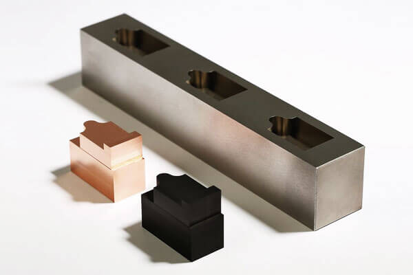
A key distinguishing feature is that the geometry of the finished part is a direct negative replica of the electrode.
This means every detail of the electrode — ribs, slots, textures and corner radii — is transferred to the workpiece, scaled by the size of the spark gap.
Historical Context
The EDM process was first developed in the 1940s by two Soviet scientists, B.R. Lazarenko and N.I. Lazarenko, who discovered that electrical discharges could be used to erode metal.
The technology was further refined during the 1950s and 1960s, and by the 1970s, Sinker EDM had become an established manufacturing process for tool and die making.
Today, it is a cornerstone of precision manufacturing, particularly in the aerospace, automotive, medical, and mould‑making industries.
2. How Does Sinker EDM Work?
Sinker EDM, also known as die-sinking EDM or electrical discharge machining, removes material through a controlled sequence of electrical discharges rather than through direct mechanical cutting.
The process uses a shaped electrode, a conductive workpiece, and a dielectric fluid.
By repeatedly generating microscopic sparks across a precisely controlled gap, Sinker EDM gradually reproduces the electrode geometry in the workpiece.
Unlike conventional machining, there is no direct contact between the electrode and workpiece during normal discharge machining.
Material removal is governed primarily by electrical pulse energy, discharge frequency, gap conditions, dielectric circulation, and electrode motion.
Dielectric Breakdown
The process begins with the electrode positioned extremely close to the conductive workpiece while both are immersed in dielectric fluid, typically EDM oil.
A controlled voltage is applied between the electrode and workpiece. Under normal conditions, the dielectric acts as an electrical insulator.
As the electrode approaches the workpiece and the inter-electrode gap reaches a suitable level, the electric field becomes sufficiently strong to ionize the dielectric locally.
The fluid then undergoes dielectric breakdown, creating a temporary conductive plasma channel between the two surfaces.
Because the discharge occurs at localized points where electrical conditions are most favorable, the machining process can concentrate energy into extremely small areas.
Electrical Discharge and Localized Energy Release
Once breakdown occurs, a short-duration current pulse passes through the plasma channel. The electrical energy is converted into intense localized thermal energy.
Temperatures within the discharge zone can reach several thousand degrees Celsius.
This extreme but highly localized energy produces rapid heating of both the workpiece and, to a lesser extent, the electrode.
The discharge does not remove material through a continuous cutting action. Instead, each individual spark creates a microscopic machining event. The combined effect of millions of these events gradually produces the desired cavity.
Melting and Vaporization of the Workpiece
The concentrated thermal energy rapidly melts and partially vaporizes a very small volume of material on the workpiece surface. A microscopic crater is formed after each effective discharge.
The dimensions of these craters depend strongly on machining parameters such as:
- Peak discharge current
- Pulse-on duration
- Pulse-off duration
- Discharge voltage
- Electrode-workpiece gap
- Dielectric conditions
Higher discharge energy generally increases the material removal rate (MRR), but it can also produce larger craters, a rougher surface, a thicker recast layer, and a greater heat-affected region.
Lower-energy finishing pulses generate much smaller craters and are therefore used when dimensional accuracy and surface quality are more important than removal rate.
Deionization and Dielectric Flushing
After each discharge pulse, the current is interrupted. The plasma channel collapses and the dielectric rapidly returns toward its insulating state.
At the same time, dielectric circulation removes molten particles, resolidified debris, and other contaminants from the machining gap.
Effective flushing is essential because accumulated debris can create unstable secondary discharges, short circuits, arcing, or uneven material removal.
The dielectric therefore performs several functions simultaneously: electrical insulation, cooling, debris removal, and restoration of stable gap conditions.
Servo Gap Control
A critical feature of Sinker EDM is the closed-loop servo system that continuously monitors electrical conditions in the machining gap and adjusts electrode position accordingly.
If the gap becomes excessively small, unstable discharges or short circuits may occur, so the electrode retracts slightly.
If the gap becomes too large, discharges become infrequent or stop, prompting the electrode to advance.
This continuous feedback maintains an appropriate working gap throughout machining.
Because the electrode progressively approaches the final cavity geometry while maintaining controlled discharge conditions, complex cavities can be generated with high repeatability.
Progressive Cavity Formation
The electrode does not normally produce the complete cavity in a single discharge. Instead, thousands or millions of individual discharges progressively erode the workpiece.
As the process continues, the electrode advances into the workpiece while maintaining its programmed trajectory. The resulting cavity increasingly conforms to the negative geometry of the electrode.
For precision mold and die applications, machining is commonly divided into roughing, semi-finishing, and finishing stages.
Roughing uses relatively high-energy pulses to remove material efficiently, while finishing uses lower-energy discharges to achieve tighter dimensional control and improved surface quality.
3. The Sinker EDM Machining Process Step by Step
Sinker EDM is not simply a spark-generation operation.
Producing a precise EDM cavity requires coordinated control of electrode geometry, workpiece positioning, dielectric circulation, discharge parameters, electrode wear, flushing, and inspection.
Step 1: Electrode Design and Fabrication
The process begins with the design of an electrode that represents the positive geometry of the cavity to be machined.
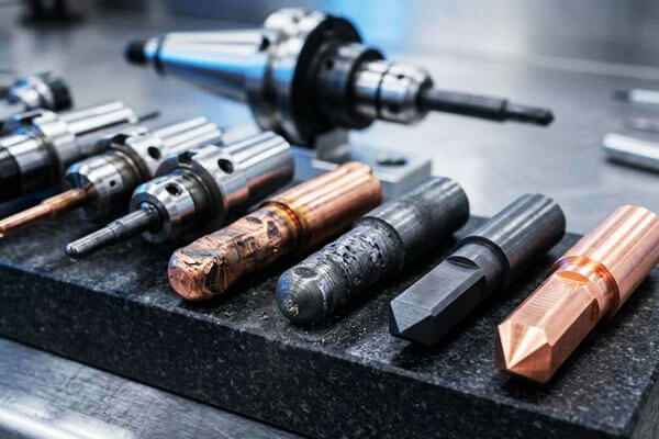
Graphite and copper are the two most widely used electrode materials, selected according to factors such as cavity complexity, required surface finish, dimensional accuracy, machining speed, and expected electrode wear.
Electrode design must account for the programmed spark gap, electrode wear, flushing requirements, and the dimensional compensation required by the EDM control system.
For complex molds and dies, multiple electrodes may be manufactured for roughing, semi-finishing, and finishing rather than attempting to achieve the final cavity with a single electrode.
The quality of the electrode directly influences the quality of the final cavity.
Errors in electrode dimensions, sharp edges, surface condition, or alignment can be transferred to the workpiece during EDM.
Step 2: Workpiece Setup and Precision Alignment
The workpiece is securely mounted on the EDM machine table and positioned within the dielectric tank.
Accurate alignment establishes the coordinate relationship between the workpiece and electrode, which is essential when machining cavities that must correspond precisely with other features.
Modern Sinker EDM machines commonly use touch probes, automatic edge detection, reference systems, or electrode measurement cycles to establish workpiece zero points and verify electrode position.
For multi-electrode machining, consistent coordinate referencing is particularly important because roughing, finishing, and detail electrodes must return to the correct locations without introducing cumulative positioning errors.
Step 3: Dielectric Preparation and Flushing
The machining zone is filled or submerged with dielectric fluid. EDM oil is widely used for conventional Sinker EDM because it provides stable electrical insulation and effective cooling.
The dielectric is continuously circulated through filtration and flushing systems to remove machining debris.
Dielectric cleanliness and temperature stability are important because contaminated or thermally unstable fluid can affect discharge behavior and dimensional consistency.
Flushing is equally critical. During machining, molten and resolidified particles accumulate in the cavity.
If these particles are not removed effectively, they can cause unstable discharges, secondary arcing, reduced material removal efficiency, and localized surface defects.
Step 4: EDM Parameter Programming
Before machining begins, the process engineer establishes the electrical and servo parameters according to the workpiece material, electrode material, machining stage, cavity geometry, and required surface finish.
Important parameters include peak current, discharge voltage, pulse-on time, pulse-off time, servo reference, polarity, flushing conditions, and electrode orbiting or movement strategies where applicable.
There is no single universal EDM parameter set. Roughing requires substantially more discharge energy than finishing, while deep narrow cavities may require different flushing and pulse conditions from open cavities.
Step 5: Roughing
Rough EDM removes the majority of the material and establishes the basic cavity geometry. Relatively high discharge energy is used to achieve a high material removal rate.
During this stage, larger electrical pulses produce larger individual craters and therefore faster erosion.
A controlled amount of machining allowance is intentionally left for subsequent operations.
The objective of roughing is not maximum surface quality, but efficient and stable bulk material removal while maintaining sufficient dimensional control for finishing.
For deep cavities, flushing conditions become particularly important during roughing because the larger quantity of eroded material can rapidly contaminate the machining gap.
Step 6: Semi-Finishing and Electrode Transition
For demanding cavities, a semi-finishing stage may be introduced between roughing and final finishing.
A separate electrode or a progressively refined electrode geometry can be used to remove the remaining machining allowance while reducing dimensional deviation and improving surface consistency.
This intermediate stage provides a controlled transition between aggressive roughing and delicate finishing.
It is particularly useful for molds and dies containing deep ribs, narrow slots, sharp corners, fine textures, or complex three-dimensional surfaces.
Step 7: Finishing
Finishing uses significantly lower discharge energy to produce the final cavity dimensions and required surface quality.
Shorter pulse durations and lower peak currents create smaller erosion craters, reducing surface roughness and minimizing the thickness of the thermally affected surface layer.
The finishing strategy must balance surface roughness, dimensional accuracy, machining time, and surface integrity.
Extremely fine finishing may require multiple passes because material removal becomes progressively slower as discharge energy decreases.
For critical tooling applications, the final surface may subsequently undergo polishing, texturing, coating, or other surface treatments depending on the required function.
Step 8: Electrode Wear Compensation
Electrode wear is an inherent characteristic of Sinker EDM. Although the workpiece is normally eroded more rapidly than the electrode, the electrode gradually changes shape during machining.
Wear is particularly significant around sharp edges, corners, small features, and areas exposed to concentrated discharge activity.
Modern EDM controls compensate for electrode wear by adjusting electrode movement and machining parameters.
For high-precision cavities, electrode wear must also be considered during electrode design and dimensional inspection.
Step 9: Final Inspection
After EDM machining, the cavity is cleaned and inspected against the engineering requirements.
Dimensional inspection may be performed using a CMM, EDM-specific probing system, optical measurement equipment, or precision gauges, depending on the component geometry and tolerance requirements.
Surface roughness can be evaluated using a profilometer, while critical cavity dimensions and geometric relationships are verified against the CAD model or drawing.
If inspection identifies localized deviations, additional EDM finishing passes can often be performed without replacing the entire manufacturing process.
4. Electrodes for Sinker EDM
The electrode is one of the most important elements in sinker EDM because its geometry is directly transferred to the workpiece through controlled electrical erosion.
Unlike a conventional cutting tool, an EDM electrode must simultaneously provide electrical conductivity, dimensional stability, wear resistance, and accurate geometric reproduction.
Electrode Materials
| Material | Key Properties | Advantages | Limitations | Typical Applications |
| Graphite | High electrical conductivity; low wear; good machinability; high melting point. | Excellent for roughing; low electrode wear; good surface finish; cost‑effective. | Brittle; may produce fine dust; requires specialised cutting tools. | Mould cavities; dies; roughing and finishing. |
| Copper | Excellent electrical conductivity; good thermal conductivity; easy to machine. | Good for finishing; fine surface finish; easy to electroplate. | Higher wear than graphite; lower material removal rate. | Finishing; small cavities; delicate features. |
| Copper‑Tungsten | High melting point; excellent wear resistance; good thermal conductivity. | Excellent wear resistance; good for fine finishing; stable dimensions. | Expensive; difficult to machine. | Precision finishing; small electrodes; high‑wear applications. |
Silver‑Tungsten |
Excellent conductivity; high melting point; good wear resistance. | Very low wear; excellent finishing. | Very expensive. | High‑precision finishing; high‑value applications. |
| Tungsten | Very high melting point; excellent wear resistance. | Very low wear; good finishing. | Extremely expensive; difficult to machine. | Specialised high‑precision applications. |
5. Accuracy, Surface Finish and Machining Capability
One of the major strengths of Sinker EDM is its ability to combine high dimensional control with the machining of geometries that are difficult or impossible to produce efficiently using conventional cutting tools.
Dimensional Accuracy
With modern CNC Sinker EDM equipment and a well-controlled process, dimensional tolerances in the few-micron to several-tens-of-microns range are achievable for suitable geometries.
The final result depends heavily on electrode wear compensation, thermal control, dielectric stability, and inspection methodology.
| Parameter | Typical Capability | Engineering Considerations |
| Dimensional tolerance | ±0.005–0.02 mm | Tighter tolerances may be achievable under optimized finishing conditions |
| High-precision tolerance | Approximately ±0.002–0.005 mm | Generally requires controlled thermal conditions, precision electrodes, and dedicated finishing passes |
| Positioning accuracy | Approximately ±0.003–0.01 mm | Depends on machine configuration, axis calibration, and workpiece setup |
| Repeatability | Approximately ±0.002–0.005 mm | Strongly influenced by machine condition and process stability |
| Electrode-to-cavity accuracy | Typically within several micrometers to tens of micrometers | Depends on electrode inspection, wear compensation, and spark-gap control |
Surface Finish
Sinker EDM produces a characteristic surface composed of microscopic discharge craters.
Surface roughness is primarily controlled by discharge energy: higher-energy pulses produce deeper and larger craters, while lower-energy finishing pulses generate a finer surface texture.
Typical achievable surface roughness ranges are shown below.
| Surface Roughness Ra | Approx. Roughness (µin) | Typical Machining Condition | Typical Use |
| 0.2–0.4 µm | 8–16 µin | Very low-energy finishing | Precision molds, optical-quality tooling surfaces requiring further polishing |
| 0.4–0.8 µm | 16–32 µin | Fine finishing | Mold cavities, precision dies, functional surfaces |
| 0.8–1.6 µm | 32–63 µin | General finishing | General precision tooling and engineering components |
| 1.6–3.2 µm | 63–125 µin | Medium-energy machining | Preliminary cavities and surfaces where moderate roughness is acceptable |
| >3.2 µm | >125 µin | High-energy roughing | Bulk material removal before finishing |
The final surface quality is not determined by current alone. Pulse duration, pulse interval, polarity, dielectric flushing, electrode material, workpiece material, and the number of finishing passes
Machining Capability
Sinker EDM is particularly valuable when the component contains deep cavities, narrow ribs, intricate pockets, small internal radii, sharp geometric transitions, or complex three-dimensional contours.
| Feature | Typical Capability | Engineering Considerations |
| Minimum feature size | Approximately 0.05–0.10 mm | Highly dependent on electrode strength, flushing, aspect ratio, and discharge energy |
| Small internal radius | Approximately 0.05–0.15 mm | Limited by electrode geometry and electrode wear |
| Deep narrow features | Aspect ratios of approximately 10:1–20:1 are possible | Flushing becomes increasingly difficult as depth increases |
| Cavity depth | Up to approximately 100–200 mm or more | Primarily limited by electrode design, flushing, machine stroke, and cavity geometry |
Complex 3D cavities |
Excellent | Complex electrode geometries can reproduce highly intricate cavity shapes |
| Hardened steel machining | Excellent | Particularly advantageous after heat treatment |
| Sharp internal features | Excellent | More practical than conventional rotating tools for many internal geometries |
| Blind cavities | Excellent | A major application of die-sinking EDM |
| Thin ribs and narrow slots | Excellent | Requires careful electrode design and controlled discharge energy |
6. What Materials Can Be Machined by Sinker EDM?
A major advantage of sinker EDM (Electrical Discharge Machining) is its ability to machine electrically conductive materials regardless of their hardness or mechanical strength.
| Material Family | Typical Materials | Suitability | Typical Sinker EDM Applications |
| Tool Steels | H13, D2, S7, P20, 4140, 4340 | Excellent | Injection molds, stamping dies, punches, forming cavities, hardened tooling |
| Stainless Steels | 304, 316, 17-4PH, 440C | Excellent | Medical components, precision tooling, aerospace parts, food-processing equipment |
| Superalloys | Inconel 625, Inconel 718, Hastelloy, Waspaloy | Excellent | Aerospace components, turbine-related tooling, chemical-processing equipment |
| Titanium Alloys | Ti-6Al-4V and other conductive titanium alloys | Excellent | Aerospace parts, medical components, precision cavities and tooling |
Cemented Carbides |
WC-Co and other conductive carbide grades | Excellent | Cutting tools, wear-resistant components, punches, dies, precision tooling |
| Copper Alloys | Copper, brass, bronze, beryllium copper | Excellent | Electrical components, precision cavities, contacts, heat-transfer components |
| Aluminum Alloys | 6061, 7075 and other conductive grades | Good | Prototypes, molds, low-volume precision components, complex cavities |
| Other Conductive Materials | Certain conductive specialty alloys and composites | Application-dependent | Specialized tooling and difficult-to-machine components |
7. Sinker EDM vs. Wire EDM vs. CNC Machining
Sinker EDM, wire EDM, and CNC machining are all precision manufacturing technologies, but they remove material in fundamentally different ways.
| Criterion | Sinker EDM | Wire EDM | CNC Machining |
| Material removal | Electrical discharge erosion | Electrical discharge erosion | Mechanical cutting |
| Tooling | Shaped electrode | Continuous wire electrode | Cutting tools |
| Material requirement | Electrically conductive | Electrically conductive | Generally machinable materials |
| Best for | Cavities, blind holes, complex 3D features | Profiles, slots, contours, through-cuts | General prismatic and rotational parts |
| Hard materials | Excellent | Excellent | Tool-dependent |
| Blind cavities | Excellent | Not normally suitable | Good, geometry-dependent |
| Complex internal geometry | Excellent | Limited by wire access | Moderate to excellent |
Sharp internal corners |
Very good, electrode-dependent | Excellent | Limited by tool diameter |
| 3D cavity machining | Excellent | Limited | Good with multi-axis machining |
| Material removal rate | Moderate | Moderate | Generally high |
| Surface finish | Excellent with finishing passes | Excellent with finishing passes | Excellent, depending on tooling |
| Physical cutting force | Essentially none | Essentially none | Significant |
| Electrode/tool wear | Electrode wear occurs | Wire is continuously consumed | Cutting-tool wear |
| Typical applications | Molds, dies, punches, cavities | Precision profiles, slots, punches | Shafts, housings, plates, structural components |
8. Advantages and Limitations of Sinker EDM
Key Advantages
- Hardness-independent machining: Cuts hardened steel, carbide and superalloys as easily as mild steel; machining can be performed after heat treatment to avoid distortion.
- Complex 3D cavity capability: Produces internal geometries, sharp corners and deep ribs that cannot be achieved with rotating cutters.
- Zero cutting forces: No mechanical contact means no deflection, no chatter, no burrs and no residual cutting stress, even for ultra-thin walls and delicate features.
- Extremely high precision: Achieves micron-level tolerances with excellent repeatability for high-volume production.
- Superior surface finish: Capable of mirror-quality surfaces that eliminate manual polishing for many mold applications.
- Highly automatable: Supports unattended overnight production with automatic electrode changers and in-process monitoring.
Inherent Limitations
- Only conductive materials: Cannot machine non-conductive ceramics, glass or most plastics.
- Lower material removal rate: Bulk material removal is slower than milling; most economical for finishing and complex features rather than roughing.
- Electrode cost and lead time: Custom electrodes add design and fabrication cost, especially for multi-electrode precision work.
- Surface recast layer: High-energy roughing creates a thin re-solidified layer and heat-affected zone; finishing passes reduce but do not completely eliminate it.
- Higher capital investment: Precision sinker EDM machines have higher purchase and operating cost than standard milling centers.
- Fluid and waste management: Dielectric fluid requires filtration and proper handling of waste sludge.
9. Applications of Sinker EDM
Sinker EDM is widely used wherever conventional cutting methods encounter limitations in material hardness, cavity geometry, feature accessibility, or internal detail.
Mold and Die Manufacturing
Moldmaking is one of the most important applications of Sinker EDM.
Injection molds, compression molds, die-casting molds, and other tooling systems frequently contain deep cavities, narrow ribs, textured surfaces, and complex internal geometries.
EDM is particularly valuable after heat treatment because hardened mold steels can be machined without the cutting forces associated with milling.
Precision Tooling
Punches, forming dies, extrusion dies, stamping tools, and precision inserts often require tight dimensional tolerances and sharp internal features.
Sinker EDM enables the production of complex cavities that would require multiple specialized cutting tools or may be inaccessible through conventional machining.
Aerospace Components
Aerospace manufacturing frequently involves high-strength, heat-resistant alloys and complex internal geometries.
Sinker EDM can be used for specialized tooling, turbine-related components, precision fixtures, and difficult-to-machine conductive materials.
Medical Manufacturing
Precision medical tooling and selected metallic components may require extremely fine features, complex cavities, and tight tolerances.
Sinker EDM is particularly suitable for manufacturing molds, forming tools, and specialized precision components.
Automotive and Energy Industries
The process is used for transmission tooling, fuel-system components, precision dies, turbine-related parts, and high-performance industrial equipment.
Electronics and Micro-Precision Components
Micro-EDM and precision Sinker EDM techniques can produce small slots, cavities, connectors, and other fine conductive features where conventional tools may be too large or mechanically fragile.
10. Conclusion
Sinker EDM is far more than simply an alternative to milling for hard materials.
It is a fundamentally different manufacturing principle that converts electrical energy into precision geometry, enabling shapes and material combinations that no mechanical cutting process can achieve.
Its unique combination of hardness independence, zero cutting forces, complex cavity capability and mirror-finish surface quality makes it irreplaceable in tool and die manufacturing, aerospace, medical devices and precision engineering.
The process does carry inherent tradeoffs: lower material removal rates, electrode wear considerations and the requirement for conductive workpieces mean it is not the optimal solution for every machining task.
When applied correctly — for hardened materials, complex internal cavities and high-precision applications — sinker EDM delivers performance that no other manufacturing process can match.
As generator technology, control systems and automation continue to advance, sinker EDM will expand further into micro-manufacturing, medical and semiconductor applications,
and integrated hybrid production workflows, reinforcing its position as one of the foundational processes of modern precision manufacturing.
FAQs
What is the difference between Sinker EDM and Wire EDM?
Sinker EDM uses a shaped electrode to machine blind cavities and complex internal geometries.
Wire EDM uses a continuously moving wire to cut through electrically conductive material and is primarily used for profiles, punches, dies, and through-features.
Why are graphite and copper commonly used as EDM electrodes?
Both materials offer good electrical conductivity and machinability.
Graphite is widely used for complex electrodes and high-temperature EDM applications, while copper can provide excellent detail reproduction and surface quality in suitable machining conditions.
Does EDM damage the surface of the workpiece?
EDM produces a thermally affected surface and may form a recast layer. With properly controlled finishing parameters, the affected layer can be minimized.
Critical components may require additional surface finishing or inspection.
How accurate is sinker EDM?
High-precision production sinker EDM machines typically hold dimensional tolerances of ±0.002 to ±0.005 mm for most features, with ultra-precision machines capable of ±0.001 mm under controlled conditions.
Accuracy depends on machine stability, temperature control and proper electrode wear management.
Can Sinker EDM machine hardened steel?
Yes. Sinker EDM can machine any conductive material, regardless of hardness. This is one of its primary advantages over conventional machining.
Is Sinker EDM expensive?
The tooling (electrode manufacturing) is expensive, and the machine time is costly due to slow material removal.
However, for complex geometries and hard materials, Sinker EDM is often the most cost‑effective option.