1. Introduction
“Sheet metal” commonly refers to metal stock from roughly 0.2 mm to 6 mm thickness (industry definitions vary).
Welding at this scale is a balancing act: deliver sufficient energy for a sound joint while minimizing distortion, burn-through and metallurgical damage.
Good outcomes require appropriate process selection (spot, arc, friction, laser, brazing), control of heat input, correct joint design and robust inspection.
2. What Is Sheet Metal Welding?
Sheet metal welding is the set of joining technologies used to create structural, functional or cosmetic joints in thin metal stock — typically from ≈0.2 mm up to ~6 mm thickness in industrial practice.
At this scale the goals are different from heavy-section welding: you must produce a sound joint while minimizing heat input, avoiding burn-through, controlling distortion, and preserving surface finish for final assembly or visible panels.
A concise definition
Sheet-metal welding is the controlled local application of energy (thermal, frictional or metallurgical) to fuse or metallurgically bond two or more sheet components so the joint meets required strength, fatigue, corrosion and cosmetic criteria, while keeping distortion and rework within acceptable limits.
What it includes (process families)
Sheet-metal welding is not one technology but a family of methods chosen to suit material, thickness, joint geometry and production volume:
- Fusion welding — melts parent metal and usually adds filler (e.g., GMAW/MIG, GTAW/TIG, laser, plasma).
- Resistance welding — generates heat by electrical resistance at the interface (e.g., spot welding).
- Solid-state welding — joins without melting (e.g., friction stir welding (FSW)).
- Brazing and soldering — capillary flow of a lower-melting filler metal to join thin members without melting the base metal.
- Mechanical fastening (rivets, clinching) and adhesives are sometimes used in combination with welding.
3. Common Welding Processes for Sheet Metal — In-Depth
Sheet-metal fabrication uses a small family of welding and joining technologies chosen to control heat input, distortion, appearance and cycle time.
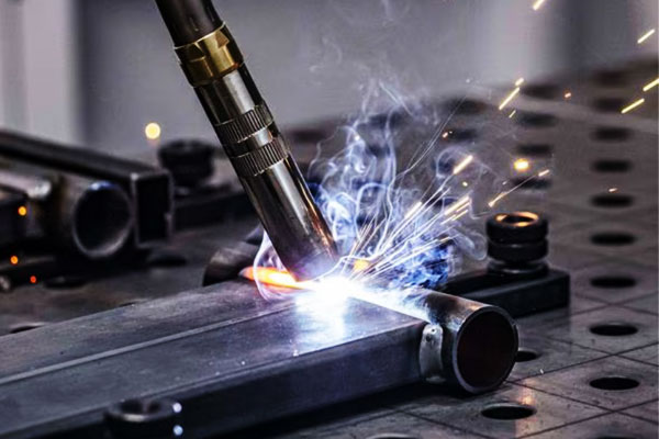
Gas Metal Arc Welding (GMAW / MIG)
GMAW forms an electric arc between a continuously fed consumable wire electrode and the workpiece.
The arc ionizes the shielding-gas atmosphere, producing a plasma column that transfers thermal energy to the wire tip and to the workpiece surface.
Metal is transferred from the wire to the weld pool in discrete modes determined by current, wire diameter, wire chemistry, gas composition and arc dynamics:
- Short-circuit transfer: the molten tip contacts the workpiece briefly and current spikes cause rapid droplet detachment; the energy per droplet is low, giving limited penetration and minimal heat input — ideal for very thin sheet.
- Globular transfer: larger, gravity-influenced droplets form and fall; this mode is unstable and produces spatter.
- Spray transfer: high-current, continuous transfer of fine droplets across the arc; high deposition and deep penetration but higher heat input (better suited to thicker sections).
- Pulsed spray: a controlled peak-and-base current waveform that produces single-droplet transfer per pulse — combines low average heat input with spray-like droplet detachment for good finish on thin-to-medium sheet.
Electromagnetic forces (pinch effect) and surface tension govern droplet formation and detachment.
The weld pool dynamics (fluid flow, Marangoni convection influenced by sulfur/oxygen, and electromagnetic stirring) control bead shape and dilution.
Shielding gas composition influences arc stability, metal transfer mode and penetration (e.g., CO₂ raises droplet size and spatter; argon–oxygen mixtures stabilize spray transfer at lower currents).
Gas Tungsten Arc Welding (GTAW / TIG)
GTAW uses a non-consumable tungsten electrode to sustain a stable arc.
The arc is constricted and attaches to the base metal, transferring heat through ionized gas (plasma).
Since the electrode is not consumed, filler metal (if used) is fed manually or automatically into the weld pool.
Key physical aspects:
- Arc column and heat concentration: TIG arcs are narrow and very controllable; small changes in current or torch angle have direct effects on local heat input.
- Shielding and arc chemistry: inert gas (typically argon) prevents oxidation; for aluminium AC TIG,
the alternating polarity creates an oxide-cleaning (electropolishing) effect during electrode-positive half-cycle and penetration during electrode-negative half-cycle—this is critical to break the tenacious aluminium oxide skin. - Thermal conduction and radiative cooling: because the electrode is cooler and heat flows into the workpiece, TIG produces a predictable fusion zone with fine control over puddle size.
- Arc initiation and stability: high-frequency or lift-start systems enable controlled arc initiation without contamination; electrode selection (thoriated, ceriated, lanthanated) tailors electron emission and arc stability for different current ranges.
TIG allows precise thermal control and minimal molten pool turbulence, making it excellent for thin sheet and cosmetic welds where arc stability and cleanliness dominate performance.
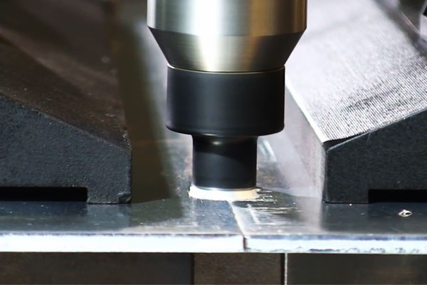
Resistance Spot Welding (RSW)
Resistance spot welding is a Joule-heating process: high current is forced through the contacting sheet stack while compressive electrode force maintains intimate contact.
Local resistance at the contact interface (and to a lesser extent the bulk sheet resistance) converts electrical energy into heat rapidly, causing local melting and formation of a weld nugget.
Important mechanistic points:
- Contact resistance vs bulk resistance: initial interface resistance dominates heating; as materials soften and molten metal forms, resistance changes dynamically — process control must account for this transition.
- Electrode force and heat distribution: compressive force squeezes out oxides and reduces contact resistance; it also controls nugget geometry by constraining molten metal and preventing expulsion.
- Thermal diffusion and cooling: after current is cut, the hold time and electrode cooling extract heat and solidify the nugget; electrode cooling (water-cooled copper electrodes) is critical to control nugget size and repeatability.
- Material and coating effects: coatings (galvanizing, organic coatings) change contact resistance and may vaporize, affecting heat localisation and electrode life — schedules must be adjusted accordingly.
RSW is fundamentally an electro-thermal-mechanical process where electrical, thermal and mechanical variables interact on millisecond timescales to produce a metallurgical bond.
Friction Stir Welding (FSW)
FSW is a solid-state, thermo-mechanical joining process. A rotating, profiled tool (shoulder + pin) is plunged into the joint and traversed along it.
Mechanisms at work include:
- Frictional heating: the rotating shoulder and pin generate heat by friction at the tool–workpiece interface, raising temperature locally to a plastically flowable but sub-melting state.
- Material plasticized flow and stirring: the pin’s geometry forces material from the leading edge to flow around the pin and consolidate in the wake, closing voids and breaking up initial oxide films—resulting in a fine-grained dynamically recrystallized “stir zone”.
- Mechanical forging action: the shoulder exerts forge pressure, consolidating the stirred material and producing a defect-free joint with no fusion-related porosity.
- Microstructural evolution: severe plastic deformation and dynamic recrystallization refine grains and often produce superior mechanical properties compared with fusion welds.
Because FSW avoids melting, it eliminates solidification defects (e.g., porosity, hot cracking) and produces low distortion; however, successful welding requires rigid backing and careful control of tool geometry and process kinematics.
Laser Beam Welding (LBW) & Hybrid Laser-Arc Welding
Laser welding transmits energy in a highly collimated beam that couples into the surface, producing two primary conduction modes:
- Conduction mode: at lower power density the laser heats the surface and melts material by conduction; penetration is shallow and heat-affected zone (HAZ) is modest.
- Keyhole mode: at high power densities the beam vaporizes a column of metal creating a vapour-filled cavity (keyhole). Intense absorption at the keyhole walls causes deep penetration as the keyhole is sustained; recoil pressure and fluid dynamics around the keyhole govern molten pool flow and stability.
Key physical factors include absorption (material, surface condition), reflectivity (highly reflective metals like Al and Cu reduce coupling), and keyhole stability (sensitive to joint fit-up and the presence of contaminants).
Hybrid laser-arc welding couples a laser with an arc (usually MIG) — the arc improves gap-bridging, preheats the joint and supplies filler while the laser provides deep penetration and narrow HAZ.
Synergy arises because the arc increases molten metal availability and reduces sensitivity to minor gaps, while the laser controls penetration and reduces distortion.
Plasma Arc Welding (PAW)
PAW generates a constricted plasma jet by forcing a plasma gas (argon, hydrogen mixes) through a fine nozzle around a tungsten electrode.
The constriction raises gas temperature and ionization, producing a focused, high-energy density arc that can be used in either:
- Transferred mode: arc attaches to the workpiece and heat transfer is concentrated; suitable for deeper penetration.
- Non-transferred (pilot) mode: arc is sustained between electrode and nozzle for specialized pre-heating or ignition tasks.
The plasma jet’s higher energy density and laminar flow produce stable penetration with better control than conventional TIG;
gas chemistry (H₂ addition) increases enthalpy and penetration at the cost of potential hydrogen pick-up in susceptible alloys.
The nozzle geometry and gas flow control are therefore critical parameters for arc shape, penetration and weld pool behavior.
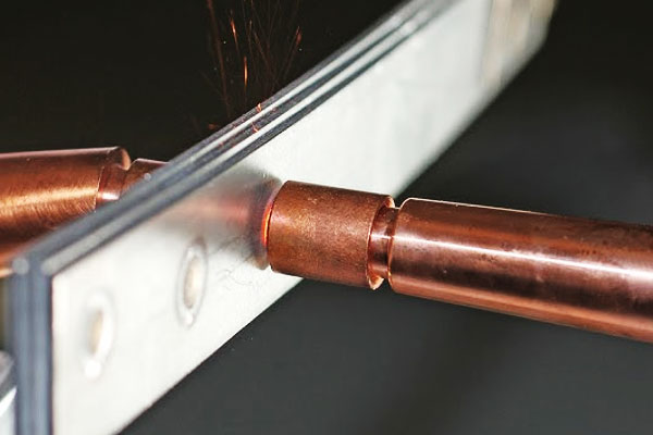
Oxy-fuel, Brazing and Soldering (for thin-gauge, non-structural)
These are capillary and temperature-controlled joining methods rather than fusion welding:
- Oxy-fuel (flame) welding/brazing: a combustion flame (O₂ + fuel gas) supplies localized heat.
In brazing the filler alloy (with melting point below base metal) is heated to flow by capillarity into the joint clearance without melting the base metals.
Flame chemistry and flux manage oxide dissolution and wetting. Oxy-fuel welding (fusion) melts parent material and filler—rare for sheet work because of coarse heat control. - Brazing: relies on wetting—the molten filler must flow over and adhere to the base metal surfaces, displacing oxides; fluxes or controlled atmospheres remove oxides and promote wetting.
Capillary action controls filler distribution; joint clearance is critical (typical brazing clearance 0.05–0.15 mm). - Soldering: similar to brazing but at lower temperatures (<450 °C); surface tension and solidification control joint integrity in electronics and light assemblies.
Because base metals are not melted, brazing and soldering produce minimal distortion and are well suited to dissimilar metal joining; success depends on metallurgy of filler, flux chemistry and strict cleanliness and clearance control.
4. Material Considerations and Weldability
Welding sheet metal is as much about material behaviour as it is about process selection.
Different alloys respond very differently to heating, pouring, solidification and cooling:
thermal conductivity controls how heat spreads, alloy chemistry controls cracking susceptibility and post-weld properties, and surface condition controls arc stability and porosity.
| Material group | Weldability (sheet) | Typical processes | Key concerns / effects | Typical filler & shielding |
| Carbon steels / Low-alloy steels | Good → Conditional | GMAW (short-circuit/pulse), GTAW, RSW | HAZ hardening on higher C or thick sections; distortion; hydrogen-induced cold cracking if moisture/contaminants present | ER70S-6 (MIG); Ar/CO₂ mixes; preheat/postheat for higher CE steels |
| Stainless steels (austenitic) | Very good | GTAW, pulsed GMAW, laser | Sensitization (carbide precipitation) if overheated → corrosion; narrow HAZ; distortion control | ER308L / ER316L (low-C filler), 100% Ar (TIG), Ar blends (MIG) |
| Stainless steels (ferritic/ martensitic) | Challenging | TIG, MIG with preheat | Martensitic: HAZ hardening and cracking risk; ferritic: grain growth & brittleness | Martensitic: matching filler + post-weld tempering; control preheat (100–300 °C) |
Aluminum & alloys |
Good — process sensitive | TIG (AC), pulsed MIG (spool-gun), laser, FSW | High thermal conductivity; tenacious oxide (Al₂O₃) needs removal; porosity and hot-cracking risk in some alloys | Al fillers: ER4043 (Si, good fluidity), ER5356 (Mg, higher strength); 100% Ar or Ar/He |
| Copper, brass, bronze | Moderate → Special handling | TIG, laser, brazing (preferred for thin) | Very high conductivity (Cu) → heat loss; brass releases Zn fumes; risk of burn-through and vaporization | Copper: Cu-Si filler; brass: brazing filler; argon shielding; good ventilation |
| Galvanized / coated steels | Condition-dependent | MIG/TIG with local strip, RSW (with controls), laser+extraction | Zinc vaporizes → porosity, spatter and toxic fumes (metal-fume fever); electrode life reduction in RSW | Strip coating at weld area or use local extraction; PPE and fume control mandatory |
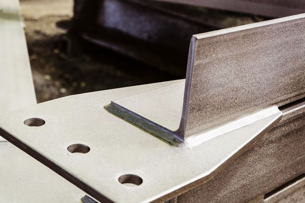
5. Joint Design, Fit-up and Edge Preparation
Good joint design reduces heat input demands and improves quality.
- Lap joints are common in spot welding and MIG for sheet; beware of trapped water or corrosion pockets.
- Butt joints on thin sheet require excellent edge preparation (square, close gap) for laser or TIG. Root gap typically 0–0.5 mm for laser; TIG may tolerate more.
- Fillet welds: For strength and stiffness, limit throat size to avoid burn-through. Typical fillet leg for 1 mm sheet is ~1–2 mm but must be carefully controlled.
- Edge bevels: Not usually needed for thin sheet; if used, keep bevel shallow to avoid excess filler and heat.
- Tolerances: For laser and FSW, fit-up tolerances are tight (±0.1 mm or better). For MIG/TIG on very thin materials, gaps <0.5 mm are common to avoid burn-through.
6. Heat Input, Distortion Control and Fixturing Strategies
Thin sheet warps easily—control strategies include:
- Lower heat input: pulse welding, higher travel speed, short-circuit transfer in GMAW, pulsed MIG/TIG.
- Intermittent stitching: weld segments with gaps to relieve stress; final pass fills gaps.
- Balanced welding sequence: weld symmetrical locations and backstep technique.
- Strong fixturing and tacks: clamps and spot tacks before full weld reduce movement.
- Heat sinks and backing bars: copper backing dissipates heat and prevents burn-through.
- Pre-bending/over-control: intentionally pre-distort then weld to end up flat after release.
7. Defects, Root Causes and Countermeasures
| Defect | Symptoms | Root Causes | Countermeasures |
| Burn-through | Hole in sheet, local melt-out | Excess heat input, slow travel, thin section | Reduce current/heat, increase travel speed, backing bar, stitch welding |
| Porosity | Pits / gas holes in weld | Contaminants, moisture, poor shielding | Clean surfaces, dry wire/filler, improve gas coverage, purge back side |
| Lack of fusion | Unfused toes or root | Low heat input, bad fit-up | Increase energy, reduce travel speed, correct joint prep |
| Cracking (hot/cold) | Cracks in HAZ or weld | High restraint, hydrogen, rapid cooling | Low-H consumables, pre/post-heat, peening or stress relief |
| Excessive spatter | Spatter around bead (MIG) | Incorrect transfer mode / gas | Switch to pulsed or short-circuit, adjust gas mix |
| Undercut | Groove at weld toe | Excessive voltage or travel speed | Reduce voltage, slow travel, adjust torch angle |
| Surface contamination / discoloration | Oxidation, poor appearance | Inadequate shielding or contamination | Improve shielding, clean prior to welding |
| Spot weld failure | Shallow or no nugget, expulsion | Incorrect electrode force, current or time | Adjust squeeze force and current schedule, replace electrodes |
8. Inspection, Testing and Quality Assurance
Quality practices for sheet welding:
- Visual inspection: weld profile, undercut, spatter, surface discontinuities.
- Dye penetrant (PT): sensitive surface crack detection.
- Ultrasonic (UT): can detect subsurface defects for thicker sheet or multi-layer.
- Cross-tension test / peel test: used to qualify spot weld strength.
- Mechanical tests: tensile, bend, and microhardness tests on representative coupons.
- Dimensional control: measure flatness and distortion; correct with fixtures or rework.
- Process control documents: WPS, PQR and welder qualifications per applicable standards.
9. Practical Tips for Welding Sheet-Metal Materials
Before you start — preparation checklist
- Identify material & temper. Confirm alloy (e.g., 304L vs 304), thickness and any coatings. If unknown, sample and test.
- Clean the joint. Remove oil/grease, dirt, mill scale and heavy oxides. For aluminium remove oxides mechanically or rely on AC TIG oxide cleaning. For galvanized, strip the zinc from the immediate weld area if possible.
- Fit-up & tack. Use tack welds every 25–50 mm for thin panels; smaller spacing (10–25 mm) for long seams or thin, flexible parts. Ensure clamps hold parts flat and aligned.
- Dry filler & consumables. Keep filler wire and rods sealed/dry; bake electrodes if required by spec.
- Plan heat control. Identify where backing bars, heat sinks or stitch welding will be used. Prepare fixtures and thermal clamps.
- Fume control & PPE. Local exhaust for galvanized, brass, stainless; respirators where required. Eye, hand and body protection appropriate to process.
Process & parameter heuristics (starter rules)
These are starting points—always validate on a coupon that reproduces stack-up, coating and clamping.
GMAW / MIG (thin steel 0.8–1.5 mm)
- Wire: 0.8 mm ER70S-6.
- Transfer: short-circuit for ≤1.5 mm; pulsed for higher quality.
- Current: 60–140 A (start low, increase carefully).
- Voltage: 16–22 V.
- Travel speed: 200–600 mm/min.
- Shield gas: 75% Ar/25% CO₂ (economical) or 98% Ar/2% O₂ (better wetting).
GTAW / TIG (thin stainless & aluminium)
- Stainless (1.0 mm): DCEN 35–90 A; Ar flow 8–15 L/min.
- Aluminium (0.8–2.0 mm): AC 60–160 A; pulse & balance control helpful; use torch starts (HF or lift) to protect electrode.
- Tungsten: 1.6–2.4 mm lanthanated/ceriated for DC, thoriated or lanthanated for AC.
Resistance Spot Welding (0.8 + 0.8 mm mild steel)
- Electrode force: 3–6 kN.
- Weld current: 7–12 kA (machine & electrode dependent).
- Weld time: 200–600 ms (depending on mains frequency and schedule).
- Maintain electrodes: dress faces regularly; monitor nugget size via destructive/non-destructive sampling.
Laser Welding (1.0 mm stainless butt)
- Power: 1–4 kW depending on travel speed.
- Speed: 1–5 m/min for thin sheet.
- Focus spot: 0.2–0.6 mm; ensure excellent edge quality and tight fit-up.
- Back purge: argon 5–15 L/min for stainless to prevent oxidation.
FSW (aluminium panels)
- Tool rpm: 800–2000 rpm; traverse 100–500 mm/min (tradeoff speed vs heat).
- Use robust backing plate; tool design critical for thin sheet to avoid plunge defects.
Controlling distortion and burn-through
- Use low heat input methods: TIG, pulsed MIG, laser or FSW when distortion or visual appearance is critical.
- Stitch/skip welding: weld 10–30 mm, skip 10–30 mm, then return to fill gaps—this limits local heat buildup.
- Balance sequence: weld symmetrically about the part and alternate sides. For seams, backstep in short segments to control shrinkage.
- Clamping & backing: rigid clamps and copper backing bars dissipate heat and prevent burn-through; sacrificial backing sheet is effective for very thin parts.
- Pre-bend and over-compensate: intentionally slightly distort opposite to predicted warpage so the part relaxes into spec after welding.
- Use heat sinks: temporary copper blocks or water-cooled fixtures under critical areas reduce HAZ and warpage.
Tack, fixturing and alignment tips
- Minimal tack size: use small tacks—just enough to hold part—then finish with full welds. For thin sheet use tack lengths of 3–6 mm.
- Tack order: place tacks to minimize gaps; do not over-tack as excessive tacks equal excessive local heating.
- Fixture heating: if parts frequently distort, consider actively water-cooled fixtures or ceramic pads to control thermal flow.
- Quick change pallets: for production, design fixtures that guarantee repeatable fit-up and minimize cycle time.
Consumables, tooling & maintenance
- Electrode & tip care: for MIG/TIG keep contact tips and nozzles clean; replace worn tips—worn tips cause erratic wire feed and inconsistent arcs.
- Wire selection: match wire chemistry to base metal and finish; maintain dry spools.
- Electrode dressing (RSW): dress copper electrodes to correct face geometry; worn electrodes reduce contact and increase current requirement.
- Torch angle & stick-out: maintain consistent stick-out for MIG (~10–20 mm typical) and proper torch angle (10–20°) to control penetration and bead shape.
10. Process Selection Matrix: When to Use Which Method
| Welding Process | Sheet Thickness Range | Material Suitability | Key Advantages | Typical Applications |
|---|---|---|---|---|
| GMAW / MIG | 0.8 – 12 mm | Carbon steel, stainless steel, aluminum | Fast, easy automation, moderate heat input | Automotive panels, industrial enclosures, structural frames |
| GTAW / TIG | 0.5 – 6 mm | Stainless steel, aluminum, copper alloys | Precise, clean welds, minimal spatter | Aerospace, high-quality assemblies, decorative panels |
| Resistance Spot Welding (RSW) | 0.5 – 3 mm | Carbon steel, stainless steel | Very fast, repeatable, minimal distortion | Automotive body panels, appliance manufacturing |
| Friction Stir Welding (FSW) | 1 – 12 mm | Aluminum, copper, magnesium | Solid-state weld, high strength, low distortion | Aircraft fuselage panels, ship hulls, aerospace components |
| Laser Beam Welding (LBW) & Hybrid | 0.3 – 6 mm | Stainless steel, aluminum, high-strength steel | Deep penetration, low heat input, high-speed | Automotive, medical devices, precision assemblies |
| Plasma Arc Welding (PAW) | 0.5 – 6 mm | Stainless steel, nickel alloys, titanium | High-quality, controlled arc, narrow HAZ | Aerospace, nuclear, high-performance components |
| Oxy-fuel, Brazing, Soldering | 0.1 – 3 mm | Copper, brass, thin steel, coated metals | Low heat, joining dissimilar metals, minimal distortion | HVAC, electronics, decorative items |
11. Conclusion
Welding sheet metal successfully requires matching process capability to the material, joint and production needs.
The key decisions are about heat management, joint fit-up, and process control. For high volumes with simple lap joints, resistance spot welding is most economical.
For cosmetic seams and repair work, TIG is preferred. Advanced, low-distortion production, laser or FSW may be the right choice. Always validate with representative coupons, control welding variables, and implement inspection and QA.
FAQs
What is the thinnest sheet I can weld?
With proper technique (laser, TIG or pulsed MIG), sheets down to 0.3–0.5 mm can be welded without burn-through. Resistance spot welding works well for lap joints at ~0.6 mm per sheet.
How can I reduce distortion in welded sheet assemblies?
Minimize heat input (higher travel speed, pulsed modes), use balanced welding sequences, strong fixturing and stitch welding. Use backing bars and clamps to act as heat sinks.
Can I weld dissimilar metals (e.g., steel to aluminium)?
Direct fusion welding of steel to aluminium is problematic due to brittle intermetallics. Preferred options are brazing, mechanical fastening, or solid-state joining (friction welding or friction stir technique) with transition layers.
Do coatings like galvanizing prevent welding?
Coatings complicate welding: zinc vaporises and can cause porosity and toxic fumes. Remove coating at the weld area or use processes tolerant of coatings (laser with extraction) and always use fume extraction and PPE.
When should I choose FSW over fusion welding?
Use FSW for aluminium alloys where you need minimal distortion, excellent mechanical properties, and no filler. FSW requires access for the rotating tool along the joint.

