
1. Introduction
Ductile Iron Shell Mold Casting represents a precision casting technique that merges the superior mechanical properties of ductile iron with the dimensional accuracy and surface quality of shell molding technology.
As industries increasingly demand complex geometries, tighter tolerances, and cost-effective production methods, this process has gained prominence in sectors such as automotive, hydraulics, machinery, and electrical equipment.
2. What Is Ductile Iron?
Composition and Microstructure
Ductile iron is an alloy of iron, carbon, and silicon, with carbon content typically ranging from 3.0% to 4.0% and silicon around 1.8% to 3.0%.
The defining characteristic of ductile iron is its spheroidal graphite structure.
During the casting process, a small amount of magnesium (usually 0.03% – 0.06%) or cerium is added to the molten iron.
These elements transform the graphite flakes, characteristic of gray iron, into spherical nodules. This change in graphite morphology has a profound impact on the material’s properties.
Key Mechanical Properties
- High Strength: Ductile iron can achieve tensile strengths ranging from 400 MPa (for grades like ASTM A536 60-40-18) to over 800 MPa (such as ASTM A536 120-90-02).
This strength makes it suitable for applications where structural integrity under heavy loads is crucial. - Ductility: It exhibits significant ductility, with elongation values that can reach up to 18% in some grades.
This allows ductile iron components to deform under stress without fracturing, enhancing their reliability in dynamic loading conditions. - Impact Resistance: The nodular graphite structure acts as tiny shock absorbers within the matrix. As a result, ductile iron has good impact resistance, far superior to gray iron.
This property is vital for applications where components may be subject to sudden impacts or vibrations.
Common Standards
- ASTM A536: Widely used in North America, this standard specifies the requirements for different grades of ductile iron.
For example, grade 60-40-18 indicates a minimum tensile strength of 60 ksi (414 MPa), a minimum yield strength of 40 ksi (276 MPa), and a minimum elongation of 18%. - EN-GJS: In Europe, the EN-GJS series of standards defines the properties and characteristics of ductile iron.
Each grade in this standard is also specified by its mechanical property requirements, ensuring consistent quality across the industry. - ISO 1083 – Global designation for spheroidal graphite iron
3. What is shell mold casting?
Fundamentals of Shell Mold Casting
Shell mold casting is an expendable mold casting process that uses resin-covered sand to form the mold. The process begins with a heated metal pattern, typically made of aluminum or cast iron.
The pattern is heated to a temperature in the range of 200 – 300°C. Resin-coated sand, usually a mixture of fine silica sand and thermosetting phenolic resin, is then introduced to the heated pattern.
The heat from the pattern causes the resin to melt and bond the sand particles together, forming a hard, thin shell around the pattern. Once the shell has hardened, it is removed from the pattern.
The mold is typically made up of two halves, known as the cope and the drag, which are assembled to create the cavity into which the molten metal will be poured.

Step-by-step process flow of ductile iron shell mold casting
Pattern Preparation:
The metal pattern is designed with precision to match the desired shape of the final casting.
Shrinkage allowances, typically around 1.5% – 2.5% for ductile iron, are incorporated into the pattern design to account for the contraction of the metal during solidification.
Draft angles, usually in the range of 0.5° – 1°, are added to ensure easy removal of the shell from the pattern.
Shell Formation:
The preheated pattern is placed in a machine where resin-coated sand is applied.
This can be done through methods such as dipping the pattern into a hopper of sand or using a sand-blasting technique to spray the sand onto the pattern.
The heat from the pattern cures the resin within 10 – 30 seconds, forming a shell with a thickness typically between 3 – 10 mm.
Mold Assembly:
The two shell halves (cope and drag) are carefully aligned and joined together. This can be achieved using adhesives, mechanical fasteners, or by clamping.
For complex parts, additional cores made of the same resin-coated sand are inserted into the mold to create internal cavities or features.
Metal Pouring:
Molten ductile iron, heated to a temperature of around 1320 – 1380°C, is poured into the assembled mold.
The smooth inner surface of the shell mold allows for efficient filling of the cavity, minimizing turbulence and the formation of defects such as porosity or inclusions.
Cooling and Finishing:
After pouring, the casting is allowed to cool within the mold.
The high thermal conductivity of the shell mold (around 1 – 2 W/m·K) accelerates the cooling process, which can take anywhere from 5 – 15 minutes for small parts.
Once cooled, the brittle shell is removed, often by vibration or air blasting. The casting may then undergo post-casting treatment.
Post-casting Treatment:
This can include operations such as heat treatment, machining, and surface finishing.
Heat treatment, such as annealing at 600 – 650°C, can further enhance the mechanical properties of the ductile iron.
Machining may be required to achieve the final dimensions and surface finish, although the need for machining is significantly reduced compared to other casting methods.
Characteristics of Shell Mold Casting
| Feature | Value / Range |
| Shell Thickness | 3–10 mm |
| Dimensional Tolerance | ±0.2 to ±0.5 mm |
| Surface Finish (Ra) | 3.2–6.3 µm |
| Mold Temperature | 200–300°C (pattern) |
| Pouring Temperature | 1320–1380°C (ductile iron) |
| Cooling Time | 5–15 minutes (depending on part size) |
| Max Typical Part Weight | ≤30–50 kg (larger possible with custom setups) |
4. Why Use Shell Mold Casting for Ductile Iron?
Shell mold casting offers significant advantages when producing ductile iron components that demand high dimensional precision, excellent surface finish, and superior mechanical integrity.
This process bridges the gap between traditional sand casting and investment casting—delivering near-net-shape results with higher efficiency and consistency.
Dimensional Accuracy and Precision
Shell mold casting delivers tight dimensional tolerances, typically in the range of ±0.2 to ±0.5 mm, which is substantially better than conventional green sand casting (±1.0–2.0 mm).
This level of precision reduces the need for secondary machining, especially on critical features like mounting holes, sealing surfaces, and complex mating geometries.
Superior Surface Finish
Shell molds provide a smooth cavity surface that imparts a fine finish to castings, typically Ra 3.2–6.3 μm.
This reduces or eliminates the need for surface grinding or polishing, which can be labor-intensive and costly in high-volume manufacturing.
Complex Geometry and Thin Walls
Due to the rigidity and fine sand grain size of the shell, the process is well-suited for casting intricate shapes, thin walls (down to 2.5–4 mm), and sharp internal features.
Dimensional Stability During Solidification
The rigid shell mold resists deformation during metal pouring and solidification, reducing common defects such as warping, swelling, or mold shift.
Process Efficiency and Waste Reduction
Shell mold casting is highly compatible with automation and mass production, particularly for parts weighing ≤30–50 kg.
5. Limitations and Challenges of Ductile Iron Shell Mold Casting

Size and Weight Restrictions
Shell molds are typically limited to parts weighing up to 30–50 kg due to the relatively thin shell structure and the mechanical strength of the mold itself.
Larger or heavier components risk mold damage during handling or metal pouring.
Higher Initial Tooling and Pattern Costs
Compared to traditional sand casting, shell mold casting requires precision-machined metal patterns that must withstand repeated heating cycles (200–300°C).
The use of resin-coated sand and automated equipment also increases upfront capital expenditure.
Thermal Limitations and Hot Spot Formation
The thin shell mold has limited thermal mass, which can lead to uneven cooling rates and localized hot spots, especially in thick sections of the casting. This may cause defects such as:
- Hot tearing
- Incomplete solidification
- Increased internal stresses
- Impact: Challenges in casting complex parts with variable wall thickness.
- Mitigation: Advanced mold design, controlled cooling, and gating optimization are essential.
Shell Thickness Control
Too thin (≤3 mm) and the shell may crack during pouring; too thick (≥10 mm) and cooling slows, coarsening nodules.
Solution: Optimize resin content (3-4%) and pattern heating time (60-90 seconds) to achieve uniform 5-8 mm shells.
Limited Mold Reusability
Shell molds are single-use and must be broken away after casting.
Although the resin-coated sand can often be reclaimed and recycled, mold components cannot be reused, increasing the consumption of materials.
6. Material Behavior in Shell Mold Casting

Metallurgical considerations
- Nodule count and shape control: The rapid cooling in shell mold casting can affect the nodule count and shape in ductile iron.
To ensure a sufficient number of well-formed nodules (aiming for 15 – 25 nodules/mm²),
careful control of the inoculation process is necessary. Inoculants, such as ferrosilicon, are added to the molten iron to promote the formation of graphite nodules.
The amount and timing of inoculant addition need to be optimized to account for the faster cooling rate in shell mold casting. - Avoiding carbide formation: In some cases, the high cooling rates can cause the formation of carbides in the ductile iron matrix.
Carbides are hard and brittle phases that can reduce the ductility of the material. To prevent carbide formation, alloying elements such as nickel may be added to the molten iron.
Nickel helps to stabilize the austenite phase during cooling, reducing the likelihood of carbide precipitation. - Ensuring proper inoculation and magnesium treatment: The addition of magnesium is critical for nodularizing the graphite in ductile iron.
In shell mold casting, the magnesium treatment needs to be carefully controlled to ensure that the correct amount of magnesium is present in the molten iron.
Too little magnesium may result in incomplete nodularization, while too much can lead to other defects.
Similarly, proper inoculation is essential to promote the formation of a fine, uniform distribution of graphite nodules.
Solidification behavior in thin shells
The thin shell mold affects the solidification behavior of ductile iron. The high thermal conductivity of the shell causes the molten metal to solidify rapidly from the surface towards the center.
This can lead to a finer grain structure near the surface of the casting. The solidification rate also impacts the formation of the ferrite-pearlite matrix in the ductile iron.
Faster cooling rates tend to promote the formation of more pearlite, which can increase the strength of the material but may slightly reduce its ductility.
Heat transfer dynamics and impact on grain structure
The heat transfer from the molten ductile iron to the shell mold plays a crucial role in determining the grain structure of the casting.
The rapid heat transfer in shell mold casting results in a steep temperature gradient between the molten metal and the mold.
This gradient causes the formation of a columnar grain structure near the surface of the casting, where the grains grow perpendicular to the mold surface.
As the distance from the surface increases, the grain structure becomes more equiaxed.
The grain structure has a significant impact on the mechanical properties of the ductile iron, with finer grains generally leading to improved strength and toughness.
7. Applications of Ductile Iron Shell Mold Castings
Ductile iron shell mold castings combine the superior mechanical properties of ductile iron with the dimensional precision and surface finish of shell mold technology.
This synergy makes them ideal for applications requiring tight tolerances, intricate geometries,
and high performance under mechanical stress or thermal cycling.

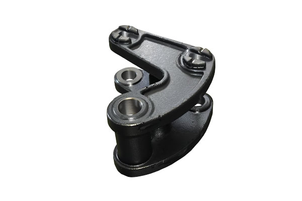
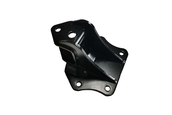
Automotive Industry
- Brackets & Mounts: Suspension brackets, steering knuckles, and alternator mounts require strength,
fatigue resistance, and precision—qualities delivered by ductile iron shell mold castings. - Transmission & Drivetrain Housings: Castings with complex geometries and internal passages benefit from the excellent surface finish and dimensional accuracy of shell molds.
- Exhaust Manifolds (in high-nickel ductile iron): Withstands thermal cycling up to 600°C in turbocharged engine systems.
Advantages: Lightweighting through near-net-shape design, reduced post-machining, and improved fuel efficiency due to precise tolerances.
Hydraulic and Fluid Power Systems
- Valve Bodies & Housings: Critical for controlling fluid flow in high-pressure environments (e.g., 3000+ psi hydraulic systems).
- Pump Components: Impellers, volutes, and gear pump housings benefit from excellent internal surface finish and dimensional repeatability.
Advantages: Leak-tight fitment, smooth flow paths, high pressure tolerance, and minimized casting porosity.
Industrial and Agricultural Machinery
- Wear Parts & Liners: Shell castings with wear-resistant ductile iron grades are used in abrasive environments like soil tillage, mining, and construction.
- Precision Gear Blanks & Pulleys: Require concentricity and balance for rotational stability—achieved with shell mold tolerances (typically ±0.3 mm or better).
Advantages: Long service life, consistent geometry, and suitability for high-load, high-wear conditions.
Electrical and Power Equipment
- Motor & Generator Housings: Require both electromagnetic compatibility (EMC shielding) and mechanical robustness.
- Switchgear Frames & Busbar Supports: Complex components cast with minimal need for secondary machining.
Advantages: Non-sparking, thermally stable, and corrosion-resistant (with appropriate coatings or alloy variants).
8. Quality Control and Testing of Ductile Iron Shell Mold Casting
Non-destructive testing (NDT)
- Radiographic Testing: This method uses X-rays or gamma rays to penetrate the casting and detect internal defects such as porosity, cracks, or inclusions.
By analyzing the radiograph, any flaws within the casting can be identified and evaluated. - Ultrasonic Testing: Ultrasonic waves are transmitted through the casting, and the reflections are analyzed to detect defects.
This technique is particularly useful for detecting internal flaws in thick sections of the casting. - Dye Penetrant Testing: A colored dye is applied to the surface of the casting. If there are any surface-breaking defects, the dye will seep into the cracks.
After removing the excess dye, the presence of defects is revealed by the dye remaining in the cracks.
Dimensional inspection
- Coordinate Measuring Machines (CMM): CMMs are used to precisely measure the dimensions of the casting.
By comparing the measured dimensions to the design specifications, any deviations can be identified.
CMMs can achieve accuracies in the range of ±0.01 mm, ensuring that the castings meet the tight tolerances required in many applications. - Optical Scanning: This technique uses lasers or structured light to create a 3D model of the casting.
The 3D model can then be compared to the CAD model of the part to detect any dimensional variations. Optical scanning is a fast and efficient way to inspect complex geometries.
Metallurgical analysis
- Microstructure Examination: Samples of the casting are polished and etched to reveal the microstructure.
By examining the microstructure under a microscope, the nodule count, nodule shape, and the proportion of ferrite and pearlite in the matrix can be determined.
This information helps to assess the quality of the ductile iron and its compliance with the required standards. - Hardness Testing: Hardness tests, such as the Brinell, Rockwell, or Vickers tests, are used to measure the hardness of the casting.
The hardness is related to the mechanical properties of the material, and deviations from the expected hardness values may indicate problems such as incorrect heat treatment or improper alloy composition. - Tensile Tests: Tensile specimens are machined from the casting and tested to determine the tensile strength, yield strength, and elongation of the material.
These mechanical properties are crucial for ensuring that the casting can withstand the intended loads in its application.
Casting defect prevention and resolution strategies
To prevent casting defects, strict control of the process parameters is essential. This includes careful monitoring of the temperature during shell formation, pouring, and cooling.
The quality of the resin-coated sand and the metal used in casting also needs to be closely controlled.
If defects are detected, strategies such as re-melting and recasting, or performing localized repairs using techniques like welding, may be employed.
However, prevention is always preferred over repair to ensure the highest quality castings.
9. Shell Mold vs. Other Casting Methods (for Ductile Iron)
| Aspect | Shell Mold Casting | Green Sand Casting | Investment Casting |
| Dimensional Accuracy | ★★★★☆ (±0.3–0.5 mm) | ★★☆☆☆ (±1.0–2.5 mm) | ★★★★☆ (±0.3–0.8 mm) |
| Surface Finish (Ra μm) | 3.2 – 6.3 | 6.3 – 25 | 1.6 – 6.3 |
| Casting Complexity | ★★★★☆ – Supports intricate features, thin walls | ★★☆☆☆ – Limited by mold strength | ★★★★☆ – Very complex parts possible |
| Tooling Cost | Medium | Low | High |
| Production Volume Suitability | Medium to High | Low to High | Low to Medium |
| Weight Range | 0.1 – 30 kg | 0.1 – >5000 kg | < 10 kg |
| Material Efficiency | Good – Less waste, thinner sections achievable | Moderate – Larger gating/riser systems required | Fair – Wax loss and higher material usage |
| Mechanical Properties (as-cast) | Excellent – Fine microstructure, low porosity | Good – Coarser structure, variable quality | Very Good – Can be tailored with alloys |
| Cooling Rate / Microstructure | Fast – Finer grains, better nodule shape control | Slow – Coarser grains, less uniform nodularity | Moderate – Controlled solidification |
| Post-Machining Needs | Minimal – Tight tolerances reduce machining | Extensive – Large allowances needed | Moderate – Often requires finishing |
| Common Applications | Precision housings, pump bodies, hydraulic parts | Engine blocks, large frames, municipal castings | Aerospace, medical, detailed precision parts |
10. What is the maximum part size for ductile iron shell mold casting?
The maximum part size for ductile iron shell mold casting typically depends on the capabilities of the foundry, but in general:
- Weight range: Up to 20–30 kg (44–66 lbs) is common for shell molding.
- Dimensions: Parts are generally limited to small-to-medium sizes, typically with maximum dimensions around 500 mm (20 inches) per side, though some foundries may handle slightly larger parts.
- Wall thickness: Shell molding excels at producing parts with thin walls and fine detail, typically 2.5 mm to 6 mm thick.
Why this limitation?
Shell mold casting uses resin-coated sand molds that are baked onto heated metal patterns.
This process offers high dimensional accuracy and surface finish but has limitations in handling large volumes of molten ductile iron due to:
- Mold strength: Thin shell molds can crack or deform under the weight of very large castings.
- Thermal stress: Larger parts generate more heat, increasing the risk of defects like hot tears or inclusions.
- Handling & pouring logistics: Shell mold equipment is optimized for smaller components.
11. Conclusion
Ductile iron shell mold casting bridges the gap between precision and strength.
It is ideal for medium-to-high volume production of geometrically complex components requiring high accuracy and consistent quality.
While tooling costs are higher, the long-term savings in machining, material use, and quality assurance make it a cost-effective solution in the right contexts.
DEZE Offers Ductile Iron Casting Services
At DEZE, we specialize in delivering high-performance ductile iron castings using a full spectrum of advanced casting technologies.
Whether your project demands the flexibility of green sand casting, the precision of shell mold or investment casting, the strength and consistency of metal mold (permanent mold) casting, or the density and purity provided by centrifugal and lost foam casting,
DEZE has the engineering expertise and production capacity to meet your exact specifications.
Our facility is equipped to handle everything from prototype development to high-volume manufacturing, supported by rigorous quality control, material traceability, and metallurgical analysis.
From automotive and energy sectors to infrastructure and heavy machinery,
DEZE delivers custom casting solutions that combine metallurgical excellence, dimensional accuracy, and long-term performance.
FAQs
How does shell mold casting affect the cost of ductile iron components?
Shell mold casting has higher upfront tooling costs ($5,000–20,000) than sand casting but reduces machining costs by 50–70% due to better surface finish and tolerances.
For volumes >10,000 parts, the total lifecycle cost is typically 10–15% lower than sand casting.
Can shell mold cast ductile iron be heat-treated?
Yes. Common heat treatments include annealing (600–650°C) for improved ductility and austempering (320–380°C) to produce high-strength ADI (austempered ductile iron) with tensile strengths up to 1,200 MPa.
What causes cold shuts in shell mold castings, and how are they prevented?
Cold shuts occur when molten metal flows in separate streams and fails to fuse, often due to low pouring temperatures or inadequate gating.
Prevention involves maintaining a pouring temperature of 1,320–1,380°C and designing gating systems with minimal turbulence (velocity <1.5 m/s).
Is shell mold casting suitable for corrosion-resistant ductile iron parts?
Yes, but corrosion resistance depends on the alloy, not the casting method.
Adding 1–3% nickel to ductile iron improves corrosion resistance in freshwater, while coating (e.g., epoxy) is required for marine environments.
How does shell mold casting impact the fatigue life of ductile iron components?
Rapid cooling in shell molds refines graphite nodules (5–10 μm) and reduces porosity, increasing fatigue strength by 10–15% compared to sand casting.
Shell mold cast parts typically achieve 250–350 MPa fatigue strength at 10⁷ cycles, suitable for dynamic applications like gears.

