
1. Introduction
Ductile Iron Lost Foam Casting (DI-LFC) is an innovative manufacturing technique that combines the superior mechanical properties of ductile iron with the geometric freedom of lost foam patterns.
In this process, a foam replica of the component—typically made from expanded polystyrene (EPS) or expanded polypropylene (EPP)—is coated and buried in unbonded sand.
When molten ductile iron (1,400–1,450 °C) is poured, the foam vaporizes, allowing metal to fill the cavity and reproduce intricate shapes without cores or parting lines.
Originally developed for aluminum alloys in the 1950s, lost foam casting has evolved through advances in foam pattern technologies, refractory coatings, and process control to accommodate ductile iron.
Today, Ductile Iron Lost Foam Casting is gaining traction in automotive, heavy equipment, and energy sectors—where lightweight, intricate, and durable castings are in ever-growing demand.
2. What Is Ductile Iron Lost Foam Casting?
Ductile Iron Lost Foam Casting (DI-LFC) is a near-net-shape manufacturing technique that marries the design freedom of lost foam patterns with the superior mechanical performance of ductile iron.
In ductile iron lost foam casting, a sacrificial foam replica—commonly made from expanded polystyrene (EPS) or expanded polypropylene (EPP)—is coated with a refractory slurry and embedded in unbonded sand.
When molten ductile iron (approximately 1,400–1,450 °C) is poured into the mold, the foam instantly vaporizes, allowing the metal to flow into the precise cavity left behind.

Key distinctions from conventional sand casting include:
- One-Time “Disappearing” Pattern: No parting lines or cores are required; the foam pattern is consumed during casting.
- Design Complexity: Undercuts, thin sections (<2 mm), internal channels, and integrated features become feasible without secondary machining.
- Surface Quality & Tolerances: Achieves as-cast surface finishes of Ra 6–12 µm and dimensional tolerances around ±0.5 %.
By leveraging ductile iron—alloyed with magnesium or rare earth elements to spheroidize graphite—this process delivers:
- Enhanced Fluidity: Better mold filling than gray iron, reducing misruns and cold shuts.
- High Ductility (2–18 % elongation): Absorbs residual thermal stresses and minimizes cracking.
- Mechanical Robustness: Tensile strengths of 400–700 MPa and impact toughness of 40–60 J.
Together, these attributes enable ductile iron lost foam casting foundries to produce complex components with 20–30 % lower tooling and post-processing costs compared to traditional sand casting, while meeting stringent performance requirements in automotive, heavy equipment, and energy applications.
3. The Lost Foam Casting Process for Ductile Iron
The Lost Foam Casting (LFC) process for ductile iron transforms a disposable foam pattern into a high-integrity metal component through a sequence of precisely controlled steps. Below is an in-depth look at each stage:

3.1 Foam Pattern Creation
- Materials: Expanded Polystyrene (EPS) at 16–32 kg/m³ density or Expanded Polypropylene (EPP) at 50–80 kg/m³ for larger, reusable patterns.
- Pattern Fabrication: CNC hot-wire cutting is common for 2D profiles; additive approaches (foam 3D printing) enable complex geometries and rapid iteration for prototype runs.
- Dimensional Accuracy: ±0.5 mm for most features; critical surfaces can be machined or coated to tighter tolerances prior to molding.
3.2 Coating and Pattern Assembly
- Refractory Coating: A water-based ceramic slurry (e.g., colloidal silica with fine alumina) is applied in 200–400 µm layers to the foam.
- Drying: Each coat is flash-dried at 80–100 °C to build a uniform shell that controls gas permeability (target Ks ≈ 1 × 10⁻⁹ m²) and resists sand erosion.
- Pattern Assembly: Multiple foam elements, gating systems, and risers are welded or glued into a single cluster to optimize gating and minimize pouring channels.
3.3 Sand Embedding and Compaction
- Sand Specification: Unbonded silica sand with 15–30 % fines, mean grain size 200–400 µm, ensures a balance of support and permeability.
- Embedding: The coated pattern cluster is placed in a flask, and sand is poured in, lightly vibrated (<0.5 g acceleration) to achieve 30–40 % porosity.
- Permeability: High void fraction allows foam vapor to escape without gas entrapment, critical for defect-free fill.
3.4 Pouring Molten Ductile Iron
- Melt Parameters: Ductile iron is melted in an induction or cupola furnace at 1,400–1,450 °C; chemical composition (C: 3.4 %, Si: 2.5 %, Mg: 0.04 %) is verified prior to pour.
- Pour Technique: A bottom-pour gating system or multiple ingates ensures laminar flow (0.5–1.0 m/s) and prevents slag inclusion.
- Foam Vaporization: Upon contact, the foam pattern vaporizes at ~200 °C; refractory coating momentarily contains gases, allowing metal to fill the cavity cleanly.
3.5 Metal Solidification
- Directional Solidification: Heat sinks (chills) and risers promote controlled solidification, reducing shrinkage porosity.
- Cooling Rate: Approximately 2–5 °C/s in thin sections yields a mixed ferritic-pearlitic matrix; slower rates in thick sections favor graphite nodule formation.
3.6 Shakeout, Cleaning, and Fettling
- Shakeout: After 30–60 minutes of cooling, the sand is vibrated away, revealing the rough casting.
- Cleaning: Shot blasting or chemical cleaning removes residual coating and foam char.
- Fettling: Gates, risers, and flash are removed by sawing or grinding; critical surfaces may be finish-machined to achieve Ra 1.6 µm.
4. Metallurgical Perspective
A robust metallurgical understanding is essential to harness the full potential of Ductile Iron Lost Foam Casting (DI-LFC).

Alloy Composition and Design Principles
Ductile iron’s properties are highly sensitive to its chemical makeup. The typical composition used in lost foam casting is engineered to promote nodule formation, control matrix structure, and avoid casting defects:
| Element | Typical Range (wt%) | Function |
| Carbon (C) | 3.2–3.8 | Promotes graphite precipitation |
| Silicon (Si) | 2.0–3.0 | Strengthens ferrite, enhances graphite shape |
| Manganese (Mn) | 0.1–0.3 | Deoxidizer; limits pearlite overgrowth |
| Magnesium (Mg) | 0.03–0.05 | Converts flake graphite into spheroids |
| Cerium/Rare Earths (RE) | 0.01–0.03 | Refines graphite; improves nodule morphology |
| Sulfur (S) & Phosphorus (P) | ≤ 0.02 & ≤ 0.10 | Controlled to reduce embrittlement and porosity |
Nodule Formation and Matrix Control
Foam pyrolysis releases carbon, increasing the iron’s carbon content by 0.05–0.1%. This requires stricter Mg control to ensure >90% spheroidal graphite (vs. 85% in sand casting).
The matrix is typically 50/50 ferrite/pearlite, balancing strength (450–600 MPa) and ductility (10–15% elongation).
Microstructure Evolution During Lost Foam Casting
The thermal-solidification environment of DI-LFC differs significantly from sand casting:
- Vaporization Dynamics: Foam vaporizes at ~600°C, generating local gas pressure that stabilizes molten metal front and slows heat extraction.
- Controlled Solidification: Foam mold acts as an insulator, promoting directional solidification and reducing hot spots.
- Resulting Microstructure:
-
- Fine skin zone: Finer nodules and increased ferrite near surface
- Core region: Pearlite-rich, higher strength zone
- Interface cleanliness: Absence of sand contact reduces surface inclusions
The cooling rate ranges from 1–5 °C/s depending on section thickness and mold configuration, affecting nodule count and matrix.
Mechanical Properties
Ductile iron cast via lost foam casting demonstrates competitive mechanical performance:
| Property | Typical Values | Remarks |
| Tensile Strength (UTS) | 400–700 MPa | Depends on matrix type |
| Yield Strength (0.2% PS) | 250–450 MPa | Higher in pearlitic matrices |
| Elongation | 10–18% | Enhanced by ferritic content and nodule shape |
| Impact Toughness (CVN) | 40–60 J | Room temperature; higher with ferrite |
| Brinell Hardness (HB) | 180–280 | Correlates with pearlite fraction |
| Fatigue Limit | ~200 MPa | Fine nodules enhance fatigue resistance |
5. Design for Ductile Iron Lost Foam Casting
Designing components for lost foam casting ductile iron requires a strategic approach that leverages the process’s unique advantages while addressing its technical constraints.
Unlike conventional sand casting, this method eliminates parting lines, cores, and draft angles, offering engineers extraordinary geometric freedom.
However, successful application demands careful attention to pattern behavior, thermal dynamics, and material characteristics throughout the design phase.
Geometric Freedom: Enabling Complex Functional Designs
One of the most transformative benefits of lost foam casting is its ability to realize intricate geometries that would be impractical—or even impossible—using traditional casting or forging techniques.
Key advantages include:
- Undercuts and Internal Cavities: Lost foam casting supports highly intricate internal structures without the use of removable cores.
For example, differential housings in automotive applications often include undercuts for axle shafts with only 5 mm clearance, eliminating the need for secondary machining.
Designs with undercuts up to 20% of part depth are achievable. - Thin-Walled Structures: The excellent fluidity of ductile iron allows the casting of wall sections as thin as 3 mm.
This is particularly beneficial for applications requiring lightweighting.
In agricultural equipment, brackets with 3 mm wall sections in non-load-bearing areas and up to 15 mm in high-stress zones have achieved weight reductions of 15–20% compared to traditional sand-cast components. - Integrated Functional Features: Assemblies traditionally fabricated through welding—such as 5-piece hydraulic manifolds—can be consolidated into a single casting.
This integration reduces component count by 40–60% and eliminates weld joints, which are responsible for up to 30% of failure incidents in certain pressure applications.
Pattern Consolidation and Gating Strategy
The foam pattern in lost foam casting is not merely a placeholder; it defines the entire casting outcome.
Design engineers must treat the pattern as an integral part of the product development process.
- Foam Pattern Uniformity: Variations in foam density can lead to inconsistent vaporization rates during pouring.
For instance, a 30 kg industrial valve body integrating multiple subcomponents may require graded foam densities—higher density (0.03 g/cm³) in thicker regions to slow vaporization, and lower density (0.015 g/cm³) in thinner areas to prevent gas entrapment. - Integrated Gating Design: Gates are built into the foam pattern rather than added to the mold, as in traditional sand casting. Effective gating systems:
-
- Deliver molten metal at velocities between 5–15 cm/s to minimize turbulence.
- Are positioned to avoid direct flow into thin-walled areas, reducing local overheating and surface defects.
- May employ “tree” configurations for multiple small parts, allowing balanced metal distribution with 3–5 components per gating system.
Dimensional Tolerances and Shrinkage Allowances
Lost foam casting of ductile iron offers improved dimensional accuracy compared to sand casting, but designers must account for solidification shrinkage and foam behavior.
- Dimensional Capabilities:
-
- Linear tolerances: ±0.5 mm for parts under 500 mm; ±0.1 mm per meter for components up to 6 meters in length.
- Flatness: Typically within ±0.3 mm/m—critical for sealing surfaces like valve or pump bodies.
- Hole positioning: Accurate to within ±0.2 mm, often eliminating the need for secondary reaming in hydraulic applications.
- Shrinkage Compensation: Ductile iron shrinks by 1.0–1.2% during solidification in lost foam casting—slightly higher than in sand casting due to faster cooling. Foam patterns must be oversized accordingly.
- For example, a 100 mm final feature requires a 101.2 mm foam dimension.
Modern CAD software with casting-specific algorithms can automate these calculations and reduce dimensional deviation errors by up to 70%.
Surface Finish and Coating Effects
Surface finish in lost foam casting is governed by both the foam pattern texture and the refractory coating applied to its surface.
- Foam Pattern Quality:
-
- Smooth EPS patterns (Ra 6.3 µm) typically yield castings with surface finishes around Ra 12.5–25 µm.
- For precision surfaces, foam patterns are post-machined to Ra 3.2 µm, enabling final cast surfaces in the Ra 6.3–12.5 µm range.
- Refractory Coating Selection:
-
- Silica-based coatings (0.5–1 mm thick) are suitable for general structural applications, achieving Ra 12.5–25 µm.
- Zirconia-based coatings (1–2 mm thick, with 5–10 µm particle sizes) are used in high-sealing applications such as hydraulic housings, where surface smoothness is essential and leakage rates must be below 0.1 cc/min.
- Coating Permeability: Optimal permeability is in the range of 10–20 Darcy. Excessively porous coatings can cause sand adhesion or gas-related defects, increasing surface roughness by up to 50%.
6. Manufacturing Considerations for Ductile Iron Lost Foam Casting
The production of ductile iron components using the lost foam casting (LFC) process demands precise control over materials, equipment parameters, and process conditions.
Every stage—from foam pattern production to molten metal pouring—directly affects casting integrity, dimensional precision, and overall cost efficiency.

Foam Pattern Material Selection
Expanded Polystyrene (EPS) is the standard material for lost foam patterns, but certain applications may benefit from alternative foams like Expanded Polypropylene (EPP).
| Foam Type | Density (g/cm³) | Characteristics | Application Notes |
| EPS | 0.015–0.03 | Cost-effective, good vaporization, available in fine cell sizes | Preferred for most applications |
| EPP | 0.03–0.06 | Higher strength, thermal resistance, slower vaporization | Used for large patterns or high thermal loads |
| Hybrid Foams | Custom | Blended EPS/EPP or variable density | Designed for graded performance within one casting |
Coating Formulation and Application
In lost foam casting of ductile iron, the foam pattern is coated with a refractory slurry to form a protective barrier between the pattern and molten metal.
The coating typically consists of refractory materials (e.g., alumina or zircon), binders (such as sodium silicate or phenolic resin), and additives for improved flow and adhesion.
The coating is applied by dipping or spraying and then dried at 60–80°C to achieve a uniform thickness (0.5–2 mm).
This layer prevents sand infiltration, regulates gas escape during foam vaporization, and influences the final surface finish of the casting.
Proper permeability (12–18 Darcy) and adhesion strength (>2 MPa) are critical for preventing defects like porosity or metal penetration.
Sand Embedding and Compaction
In ductile iron lost foam casting, unbonded silica sand is used to surround and support the foam pattern during pouring.
The embedding process involves placing the coated foam pattern into a flask and filling it with dry, fine-grain silica sand (typically 90–150 mesh) to ensure uniform support and permeability.
Compaction is achieved through controlled vibration (50–60 Hz), which allows the sand to flow and densely pack around the pattern, reaching a bulk density of 65–70%.
Vacuum assistance (-0.05 to -0.08 MPa) is often applied during compaction and pouring to stabilize the mold and enhance gas evacuation.
Proper compaction ensures dimensional accuracy, minimizes pattern distortion, and supports defect-free casting.
Furnace and Pouring Parameters for Ductile Iron
Ductile iron for lost foam casting is typically melted in medium-frequency induction furnaces, offering precise temperature control and low gas pickup.
The ideal pouring temperature ranges from 1,350°C to 1,400°C, which is higher than in conventional sand casting to ensure complete vaporization of the foam pattern.
Chemical composition must be tightly controlled:
- Carbon: 3.5–3.8% for good fluidity
- Silicon: 2.0–2.8% to promote spheroidal graphite
- Magnesium: 0.04–0.06% to ensure nodularity
- Sulfur: <0.03% to prevent graphite degeneration
Pouring should be steady, at rates of 0.5–2 kg/s, maintaining a smooth metal front (5–15 cm/s) to avoid turbulence, misruns, and gas entrapment.
7. Quality Control and Defect Mitigation
- Common Defects: Porosity (1–3 % by volume), inclusions, misruns, veining
- Process Monitoring: Thermocouples in mold, coating viscosity checks
- NDT: Ultrasonic testing (UT) to detect internal porosity ≥1 mm; radiography for critical parts
- Metallography & Mechanical Testing: Per ASTM A897 for ductile iron: tensile, hardness, and Charpy V-notch tests
8. Advantages of Ductile Iron Lost Foam Casting
Exceptional Geometric Complexity
- No Parting Lines or Draft Angles: Enables creation of intricate shapes such as undercuts, internal cavities, and lattice structures.
- Thin-Wall Capability: Wall thicknesses as low as 3 mm are achievable, compared to 6–8 mm in conventional sand casting.
Pattern Integration and Assembly Reduction
- Design Consolidation: Multiple components can be cast as a single piece, reducing part count by 30–60%.
- Reduced Welding/Assembly: Eliminates joining operations, which are typically failure-prone in high-pressure applications.
Process Repeatability and Automation
- Robust for High Volumes: With proper process control, lost foam casting is well-suited to automated production environments (e.g., automotive).
- Sand Reusability: Up to 95% of unbonded sand is recyclable, minimizing environmental impact and raw material cost.
Superior Surface Finish and Tolerances
- Surface Finish: Achieves Ra values of 12.5–25 μm, superior to green sand castings (Ra 50–100 μm).
- Dimensional Accuracy: Linear tolerances of ±0.5 mm for parts under 500 mm reduce or eliminate machining.
Material Efficiency and Cost Savings
- Less Material Waste: Near-net shape casting reduces excess material and machining allowances.
- Lower Tooling and Production Costs: Disposable foam patterns avoid the need for expensive, complex coreboxes.
Mechanical Integrity of Ductile Iron
- High Strength and Ductility: Tensile strength up to 700 MPa and elongation up to 18%, outperforming gray iron and some steels.
- Fatigue Resistance: Graphite nodules in ductile iron improve crack resistance and long-term durability.
9. Applications of Ductile Iron Lost Foam Casting
Ductile iron lost foam casting is widely used across multiple industries for producing high-performance, geometrically complex components. Key application areas include:

Automotive Industry
- Suspension control arms
- Exhaust manifolds
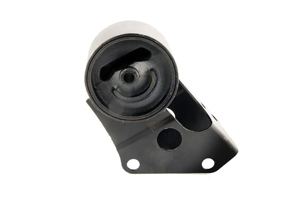
- Engine mounts
- Differential housings
- Brackets and crossmembers
Heavy Machinery and Agricultural Equipment
- Hydraulic valve bodies
- Pump and motor housings
- Gearboxes and transmission cases
- Engine beds and support frames
Power and Energy Sector
- Turbine casings
- Compressor housings
- Pump impellers
- Pipeline connectors and fittings
Industrial Equipment and Infrastructure
- Bearing housings
- Machine tool bases
- Structural brackets
- Manhole covers and drainage components
Emerging and Advanced Applications
- Prototyped aerospace components
- Electric vehicle motor housings
- 3D-printed pattern-based castings
- Custom low-volume industrial parts
10. Comparison to Other Casting Processes
| Criteria | Lost Foam Casting | Green Sand Casting | Investment Casting | Shell Mold Casting |
| Pattern Type | Single-use foam pattern | Reusable wood/metal pattern | Wax pattern (lost) | Heated metal pattern |
| Geometric Complexity | Excellent — undercuts, internal channels, no parting lines | Moderate — limited by parting requirements | Excellent — high precision & fine detail | Good — suitable for moderately complex parts |
| Surface Finish (Ra) | 12.5–25 µm (typical), 6.3–12.5 µm (with fine coating) | 25–50 µm | 3.2–6.3 µm | 6.3–12.5 µm |
| Dimensional Accuracy | ±0.5 mm / 500 mm | ±1.5 mm / 500 mm | ±0.1–0.5 mm / 100 mm | ±0.5 mm / 300 mm |
| Minimum Wall Thickness | 3 mm (possible with good flow and coatings) | ≥6 mm | ≥1.5 mm | 3–5 mm |
| Tooling Cost | Medium — foam tooling required | Low | High — wax tooling and ceramic shell | Medium |
| Production Volume Suitability | Low to high — suited for complex, medium-volume production | Medium to very high | Low to medium volume | Medium volume |
| Material Compatibility | Ductile iron, gray iron, steel, aluminum | Wide — iron, aluminum, bronze, steel | Wide — superalloys, steels, titanium | Iron, steel, aluminum |
| Post-Processing Needs | Low to moderate — minimal flash or parting lines | High — flashing, gating removal | Moderate — shell removal and gating | Moderate |
| Lead Time | Medium — pattern production adds time | Short — especially for basic geometries | Long — multi-step mold and shell creation | Medium |
| Typical Applications | Engine brackets, valve bodies, hydraulic manifolds | Pump housings, engine blocks, machine bases | Aerospace vanes, precision implants | Gearboxes, pressure casings, covers |
11. Challenges and Future Directions
- High-Volume Consistency: Variability in foam density and sand compaction limits scale-up; automation (robotic pouring, AI-driven monitoring) is addressing this.
- Digital Integration: 3D scanning and simulation (e.g., MAGMAsoft) reduce pattern design time by 50%.
- Alloy Development: Microalloying with niobium (0.05–0.1%) increases tensile strength to 700 MPa while retaining ductility.
- Advanced Coatings: Nanocomposite coatings (alumina + carbon nanotubes) improve permeability by 30%.
12. Conclusion
Ductile Iron Lost Foam Casting merges the mechanical excellence of nodular iron with the design freedom of foam patterns, enabling efficient production of complex, high-performance components.
Continued advances in pattern technology, coatings, and process simulation promise to further enhance DI-LFC’s competitiveness in automotive, heavy equipment, and energy markets.
DEZE Offers Ductile Iron Casting Services
At DEZE, we specialize in delivering high-performance ductile iron castings using a full spectrum of advanced casting technologies.
Whether your project demands the flexibility of green sand casting, the precision of shell mold or investment casting, the strength and consistency of metal mold (permanent mold) casting, or the density and purity provided by centrifugal and lost foam casting,
DEZE has the engineering expertise and production capacity to meet your exact specifications.
Our facility is equipped to handle everything from prototype development to high-volume manufacturing, supported by rigorous quality control, material traceability, and metallurgical analysis.
From automotive and energy sectors to infrastructure and heavy machinery, DEZE delivers custom casting solutions that combine metallurgical excellence, dimensional accuracy, and long-term performance.
FAQs
Why choose ductile iron for the lost foam casting process?
Ductile iron offers an excellent combination of strength, ductility, and castability. Its high fluidity supports the accurate reproduction of complex foam patterns,
while its mechanical properties—such as elongation (2–18%) and tensile strength (400–700 MPa)—suit structural applications across demanding industries.
What are the limitations of lost foam casting ductile iron?
Limitations include sensitivity to foam quality and pattern handling, longer lead times for pattern production,
and the need for careful control of coating permeability and pouring temperature. For very large or low-volume parts, tooling costs may also be a factor.
How does the process affect surface finish?
Surface roughness depends on the pattern and refractory coating.
Typical surface finish ranges from Ra 12.5 to 25 μm. With high-quality foam and zirconia-based coatings, Ra values as low as 6.3 μm can be achieved.
Is ductile iron lost foam casting environmentally friendly?
Yes, it has several environmental advantages. Foam residue is minimal and non-toxic, sand is 90–95% recyclable,
and the process eliminates the need for binders and core sands found in conventional casting, reducing waste and emissions.
Can this method be used for high-volume production?
Absolutely. With automated foam molding lines and optimized pouring systems, the process supports high-volume runs—especially for automotive and industrial components.
However, pattern tooling and setup must be amortized over larger quantities for economic viability.

