
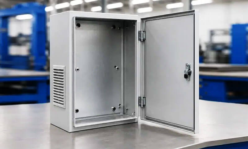
Sheet metal is one of the most versatile materials in modern manufacturing. From automotive body panels and aircraft fuselages to electronic enclosures and building cladding, sheet metal components are everywhere.
However, sheet metal alone is rarely sufficient—it must be joined to create assemblies, structures, and finished products.
The method used to join sheet metal components is critical to the strength, durability, appearance, and cost of the final product.
Choosing the right sheet metal joint is not a simple matter. The selection depends on a range of factors: the material type and thickness, the required strength, the aesthetic requirements, the production volume, and the service conditions.
A poorly chosen joint can lead to premature failure, costly rework, or even safety hazards.
This article provides a comprehensive guide to the common types of sheet metal joints, their classification, and a practical selection framework.
1. What Is a Sheet Metal Joint?
A sheet metal joint is a connection between two or more sheet-metal components designed to maintain their relative position and transfer mechanical or functional loads.
The sheets can be connected along their surfaces, edges, corners, or formed features.
The connection may be permanent, removable, or mechanically interlocked, depending on the manufacturing method.
In engineering terms, a joint should be considered a load-transfer region rather than simply a connection point. Forces entering one sheet must be transferred through the joint and into the adjoining sheet.
The geometry of that load path strongly influences stress concentration, deformation, fatigue life, and failure behavior.
For example, two flat sheets can be joined edge-to-edge with a butt joint, overlapped with a lap joint, or arranged perpendicular to each other to create a T-joint.
These different geometries can then be joined through welding, riveting, screws, clinching, adhesives, or formed seams.
2. How Are Sheet Metal Joints Classified?
Sheet metal joints can be classified from several engineering perspectives. The most practical approach is to consider how the joint is assembled, how it is manufactured, and how it transfers loads.
By Type of Connection
Based on whether the assembled components can be separated, sheet metal joints are commonly divided into permanent, temporary, and semi-permanent joints.
| Category | Description | Typical Examples |
| Permanent joints | Designed to remain assembled throughout the service life and generally require damage or destructive operations for removal. | Welded joints, brazed joints, soldered joints, structural adhesive joints, riveted joints |
| Temporary joints | Designed for repeated assembly and disassembly without normally damaging the sheet-metal components. | Bolted joints, screwed joints, removable mechanical fasteners |
| Semi-permanent joints | Can be separated, but removal generally requires tools, deformation, or replacement of part of the joint. | Clinched joints, some self-piercing fasteners, lock seams |
The classification is not absolute. For example, a riveted joint is normally considered permanent in manufacturing, but a rivet can technically be removed by drilling or cutting.
Therefore, the practical distinction is based on the intended service and disassembly method, not merely whether physical removal is possible.
By Manufacturing Method
A second and more manufacturing-oriented classification is based on the process used to create the connection.
| Category | Description | Typical Examples |
| Welded joints | Sheets are joined primarily through localized heat, with or without pressure and filler metal, depending on the welding process. | MIG welds, TIG welds, resistance spot welds, laser welds, seam welds |
| Mechanical joints | Connection is produced through fasteners, mechanical interlocking, or localized plastic deformation of the sheet. | Riveted, bolted, screwed, clinched joints |
Adhesive joints |
Surfaces are bonded using a suitable adhesive system rather than a conventional mechanical fastener or fusion process. | Epoxy, acrylic, polyurethane adhesive joints |
| Integral formed joints | The sheet itself is bent, folded, punched, or formed to create the connection, minimizing or eliminating separate joining components. | Hem joints, lock seams, tuck joints, formed interlocks |
By Joint Geometry and Load Transfer
Sheet metal joints can also be classified according to the physical arrangement of the sheets and the resulting load path.
This is particularly important for structural design because the geometry determines how forces are transferred through the connection.
| Category | Description | Typical Examples |
| Lap joints | One sheet overlaps another, creating an overlapping connection region. | Spot-welded lap joint, riveted lap joint, adhesive lap joint |
| Butt joints | Two sheets meet approximately edge-to-edge, generally in the same plane. | Butt weld, laser-welded butt joint |
| Edge joints | Adjacent sheet edges are connected along their boundaries, often through folding, welding, or forming. | Hem joint, folded edge, edge weld |
T-joints |
One sheet meets another approximately perpendicular to it, producing a T-shaped configuration. | Fillet-welded T-joint, mechanically fastened T-joint |
| Corner joints | Two sheets meet at an angle, commonly around 90°, to form an external or internal corner. | Welded corner joint, formed corner joint |
3. Welded Sheet Metal Joints
Welding is one of the most widely used methods for creating permanent sheet metal joints. It uses heat, pressure, or a combination of both to establish a metallurgical connection between components.
The most appropriate welding process depends on the sheet material, thickness, joint geometry, required weld quality, production volume, heat input, and dimensional tolerance.
MIG Welding (Metal Inert Gas)
MIG welding, formally classified within Gas Metal Arc Welding (GMAW), uses a continuously fed consumable wire electrode to generate an electric arc and melt the base material.
A shielding gas protects the molten weld pool from atmospheric contamination.
Depending on the application, shielding gases may include argon-based mixtures, carbon dioxide, or other gas blends; therefore, describing all MIG shielding gases as purely inert is technically inaccurate.

| Aspect | Details |
| Process | A continuously fed wire electrode melts under an electric arc to form a weld pool. Shielding gas protects the molten metal from atmospheric contamination. |
| Best for | Mild steel, stainless steel, and aluminum sheet and plate. |
| Advantages | High welding speed; continuous wire feeding; high deposition rate; relatively easy to automate; suitable for a wide range of joint configurations. |
| Limitations | Can generate spatter and heat distortion; shielding gas is normally required; process control becomes more demanding on very thin sheet. |
Typical applications |
Automotive components, machinery frames, enclosures, general fabrication, brackets, structural sheet-metal assemblies. |
| Joint types | Butt joints, lap joints, fillet joints, T-joints, and corner joints. |
| Material thickness | Commonly used for approximately 0.8–6 mm sheet, although the practical range depends on material, equipment, joint design, and welding parameters. |
| Welding speed | Approximately 20–60 cm/min for many sheet-metal applications, depending strongly on material thickness and process settings. |
| Cost | Moderate. |
MIG welding is particularly attractive when productivity and flexibility are more important than achieving the minimum possible heat input.
It is widely used in both manual and robotic fabrication because the continuously supplied wire supports relatively high production rates.
TIG Welding (Tungsten Inert Gas)
TIG welding, or Gas Tungsten Arc Welding (GTAW), uses a non-consumable tungsten electrode to establish the arc. The filler metal, when required, is added separately.
An inert shielding gas, typically argon or a suitable argon-based mixture, protects the weld area from atmospheric contamination.
TIG is valued for its precise heat control, excellent weld appearance, and ability to produce high-quality welds on thin materials.
| Aspect | Details |
| Process | An electric arc is generated between a non-consumable tungsten electrode and the workpiece. Filler metal may be added separately while shielding gas protects the weld zone. |
| Best for | Stainless steel, aluminum, nickel alloys, copper alloys, and thin sheet requiring precise heat control. |
| Advantages | Excellent weld quality; precise control of heat input; low spatter; clean weld appearance; suitable for critical and visible joints. |
| Limitations | Slower than MIG welding; lower deposition rate; requires greater operator skill; generally less productive for high-volume fabrication. |
Typical applications |
Stainless-steel enclosures, food-processing equipment, precision fabrication, aerospace components, decorative assemblies, and thin-wall tubing. |
| Joint types | Butt, lap, corner, fillet, and T-joints. |
| Material thickness | Particularly effective for thin sheet, commonly from approximately 0.5–6 mm depending on material and joint configuration. |
| Welding speed | Approximately 5–30 cm/min for many manual sheet-metal applications. |
| Cost | Moderate to high. |
TIG is often selected when weld appearance, dimensional control, and metallurgical quality are critical.
Its slower production rate makes it less attractive for high-volume applications where resistance welding or automated laser welding can provide substantially higher throughput.
Resistance Spot Welding
Resistance spot welding joins overlapping sheets by passing a controlled electrical current through the contact area while applying pressure with electrodes.
Electrical resistance generates localized heat, producing a weld nugget between the sheets without requiring filler metal.
It is particularly important in high-volume manufacturing because the process can be rapidly automated.
| Aspect | Details |
| Process | Two or more overlapping sheets are clamped between electrodes. Electrical current passes through the interface, generating localized resistance heat that forms a weld nugget under pressure. |
| Best for | Low-carbon steel, stainless steel, galvanized steel, and certain aluminum sheet assemblies. |
| Advantages | Extremely fast; highly suitable for automation; no filler metal; relatively low overall heat input; repeatable production process. |
| Limitations | Requires suitable electrode access; primarily intended for overlapping sheets; joint geometry and material stack-up must be carefully controlled. |
Typical applications |
Automotive body structures, appliances, electrical cabinets, metal furniture, and high-volume sheet assemblies. |
| Joint types | Primarily lap and overlapping joints. |
| Material thickness | Commonly used for relatively thin sheet, with capability depending on material and equipment. |
| Welding speed | Each weld can typically be completed in a fraction of a second, making the process highly productive. |
| Cost | Low per joint at high production volumes, but equipment and tooling costs can be significant. |
Laser Welding
Laser welding uses a concentrated laser beam to produce highly localized melting at the joint.
Its exceptionally focused energy source allows high welding speeds and a relatively small heat-affected region compared with many conventional arc-welding processes.
| Aspect | Details |
| Process | A focused laser beam delivers concentrated energy to the joint, locally melting the material and forming a metallurgical bond as the molten region solidifies. |
| Best for | Stainless steel, carbon steel, aluminum, and other compatible sheet metals requiring precise, high-speed welding. |
| Advantages | High welding speed; narrow welds; relatively low distortion; excellent repeatability; well suited to automation and robotic production. |
| Limitations | High equipment cost; requires precise joint fit-up and process control; reflective materials and complex geometries may require specialized systems. |
Typical applications |
Automotive body components, battery enclosures, electronics, precision housings, heat exchangers, and high-volume precision fabrication. |
| Joint types | Butt, lap, edge, and selected fillet configurations. |
| Material thickness | Particularly effective for thin and medium-gauge sheet, with the practical range determined by laser power and material. |
| Welding speed | Can range from hundreds to thousands of mm/min depending on material, thickness, laser power, and joint design. |
| Cost | High initial investment; potentially economical for high-volume production. |
Seam Welding
Seam welding produces a series of overlapping resistance welds, commonly using rotating wheel electrodes, to create a continuous or leak-resistant joint.
It is especially useful when a sheet-metal assembly requires not only mechanical connection but also sealing against liquids or gases.
| Aspect | Details |
| Process | Overlapping sheets pass between rotating electrodes while electrical current and pressure create a continuous series of overlapping weld nuggets. |
| Best for | Thin steel and stainless-steel sheet requiring continuous or leak-resistant joints. |
| Advantages | Continuous joining; good sealing capability; high production rate; no filler metal; suitable for automated production. |
| Limitations | Primarily suited to overlapping sheet configurations; tooling and electrode access can restrict joint geometry. |
Typical applications |
Fuel tanks, containers, ducts, drums, radiators, and sealed sheet-metal assemblies. |
| Joint types | Primarily lap and overlapping joints. |
| Material thickness | Generally suited to thin sheet, with the exact range depending on material and equipment. |
| Welding speed | Commonly from several hundred mm/min upward, depending on material, thickness, and required weld quality. |
| Cost | Moderate to high, with good productivity in repetitive production. |
4. Riveted Sheet Metal Joints
A riveted sheet metal joint uses a mechanical fastener called a rivet to connect two or more sheets.
During installation, the rivet is placed through aligned holes and mechanically deformed or expanded to form a head that clamps the sheets together.
Unlike welding, riveting does not require melting the base metal. This makes it particularly useful when minimizing thermal distortion is important or when joining materials that are difficult to weld.

Common Rivet Types
| Rivet Type | Characteristics | Typical Applications |
| Solid rivet | Strong and reliable; requires access for forming the opposite head. | Aerospace, structural assemblies |
| Blind rivet | Installed from one side; useful where rear access is limited. | Enclosures, maintenance, general fabrication |
| Self-piercing rivet | Pierces and mechanically joins sheet without a pre-drilled hole in suitable materials. | Automotive lightweight structures |
| Tubular rivet | Hollow or partially hollow shank; requires less forming force than solid rivets. | Appliances, electronics, light assemblies |
| Semi-tubular rivet | Partially hollow end simplifies installation. | Consumer products, mechanical assemblies |
Riveted Joint Characteristics
| Aspect | Details |
| Process | Sheets are aligned and mechanically fastened by installing and deforming a rivet, or by using a specialized self-piercing or blind-rivet mechanism. |
| Best for | Aluminum, steel, stainless steel, and mixed-material sheet assemblies where mechanical joining is preferred. |
| Advantages | No heat; low distortion; suitable for dissimilar materials; good repeatability; some types require access from only one side. |
| Limitations | Requires holes or specialized piercing capability for many rivet types; adds fastener weight; creates local stress concentrations; removal can be difficult for permanent rivets. |
Typical applications |
Aerospace structures, automotive assemblies, HVAC equipment, enclosures, trailers, metal furniture, and repair work. |
| Joint types | Mainly lap joints and butt joints using cover plates. |
| Material thickness | Depends on rivet type, diameter, material, and joint configuration; suitable for thin to medium sheet assemblies. |
| Production speed | High when automated riveting systems are used. |
| Cost | Low to moderate per joint, although tooling and automated equipment can increase initial investment. |
5. Screwed and Bolted Sheet Metal Joints
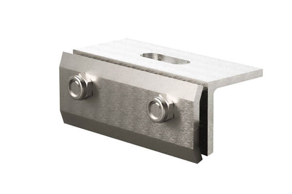
Screwed and bolted joints are removable mechanical connections that use threaded fasteners to clamp two or more sheet-metal components together.
Unlike welded or adhesively bonded joints, they can normally be disassembled for inspection, maintenance, replacement, or repair.
Screws are particularly common in thin-sheet assemblies because self-tapping and thread-forming designs can create threads directly in the sheet or in a pre-formed hole, while bolts and nuts are more suitable when higher clamping forces or repeated disassembly are required.
Screwed and Bolted Joint Characteristics
| Aspect | Details |
| Process | Aligned sheets are connected using screws, bolts, nuts, washers, threaded inserts, or other mechanical fasteners. The fastener generates clamping force that holds the components together. |
| Types | Bolts + nuts, self-tapping screws, machine screws, rivet nuts, weld nuts. |
| Best for | Steel, stainless steel, aluminum, galvanized sheet, and assemblies requiring removable connections. |
| Advantages | Removable; easy to inspect and repair; no heat input; suitable for many material combinations; simple tooling; well suited to low- and medium-volume production. |
| Limitations | Fastener holes reduce the net section of the sheet; vibration can cause loosening; thin sheet may have limited thread engagement or pull-out resistance; fasteners add weight and local stress concentrations. |
Typical applications |
Electrical enclosures, machine guards, HVAC equipment, cabinets, automotive components, appliances, and equipment requiring regular maintenance. |
| Joint types | Lap, butt with cover plate, flange, corner, and bracket joints. |
| Material thickness | Particularly common for thin to medium sheet-metal assemblies; practical thickness depends on fastener type and joint design. |
| Production speed | High for automated screwdriving and fastening systems; moderate for manual assembly. |
| Cost | Low to moderate, depending on fastener type and automation level. |
6. Clinched and Mechanical Sheet Metal Joints
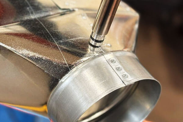
Clinching is a cold mechanical joining process in which overlapping sheets are locally formed by a punch and die to create a permanent mechanical interlock.
Unlike conventional riveting, no separate fastener is required, and unlike welding, the process introduces essentially no fusion heat into the joint.
Clinching is particularly attractive for thin-sheet assemblies because it can be fast, clean, repeatable, and highly compatible with automated production.
Clinching Joint Characteristics
| Aspect | Details |
| Process | A punch and die plastically deform overlapping sheets to create a mechanical interlock. Material flows into a designed undercut or interlocking region without melting the sheets. |
| Best for | Ductile steels, stainless steel, aluminum, coated sheet, and selected mixed-material assemblies. |
| Advantages | No filler metal or separate fastener; very low thermal distortion; fast cycle time; suitable for automation; can join coated materials; relatively clean process. |
| Limitations | Requires sufficient sheet ductility; joint strength is highly dependent on material and tooling; visible indentation remains; not suitable for every geometry or material combination. |
Typical applications |
Automotive body components, HVAC assemblies, appliances, electrical enclosures, furniture, and high-volume sheet-metal products. |
| Joint types | Primarily overlapping lap joints, including selected flange and corner configurations. |
| Material thickness | Particularly suitable for thin sheet, with practical thickness determined by the material stack-up and tooling. |
| Production speed | Very high; individual joints can typically be produced rapidly in automated systems. |
| Cost | Low per joint at high production volumes after tooling is established. |
7. Adhesive-Bonded Sheet Metal Joints
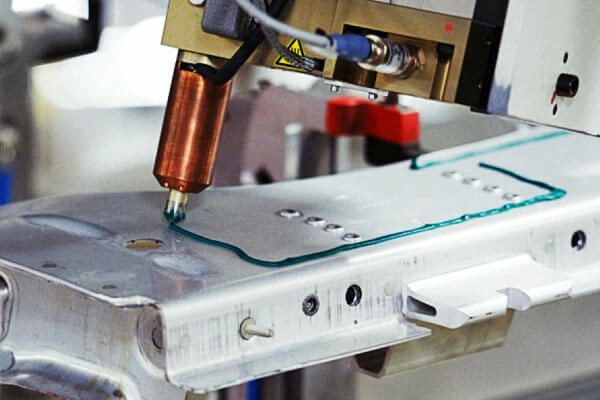
Adhesive bonding connects sheet-metal components through a polymeric adhesive layer rather than through a conventional mechanical fastener or fusion weld.
Structural adhesives can transfer load continuously over a relatively large bonded area, making them particularly useful when engineers want to reduce localized stress concentrations.
Adhesive bonding is widely used in automotive, transportation, electronics, appliances, and lightweight structures, particularly where low distortion, smooth external surfaces, vibration damping, or joining of dissimilar materials is important.
Adhesive-Bonded Joint Characteristics
| Aspect | Details |
| Process | Adhesive is applied between prepared surfaces and cured under specified time, temperature, pressure, or environmental conditions to form the joint. |
| Types | Epoxy, acrylic, polyurethane, cyanoacrylate. |
| Best for | Steel, stainless steel, aluminum, coated metals, and compatible dissimilar materials. |
| Advantages | Distributes stress over a large area; no fusion heat; low distortion; excellent surface appearance; can seal the joint; useful for dissimilar materials; provides some vibration damping. |
| Limitations | Requires proper surface preparation; cure time may affect productivity; performance can depend on temperature, moisture, chemicals, and aging; inspection can be more difficult than with visible mechanical fasteners. |
Typical applications |
Automotive body panels, battery enclosures, HVAC assemblies, electronics, appliances, composite-metal structures, and lightweight transportation components. |
| Joint types | Lap joints, scarf joints, flange joints, and selected butt or corner configurations. |
| Material thickness | Suitable for a wide range of sheet thicknesses, provided the adhesive and joint geometry are properly designed. |
| Production speed | Moderate to high depending on adhesive chemistry and curing method. |
| Cost | Moderate; can become highly economical when it eliminates fasteners or secondary sealing operations. |
8. Integral Formed Sheet Metal Joints
Integral formed sheet metal joints are created by cutting, bending, folding, or mechanically interlocking the sheet itself, eliminating the need for separate fasteners or fusion welding.
They are particularly effective in high-volume sheet metal manufacturing because the joint can be incorporated directly into the flat pattern and produced through stamping, punching, laser cutting, press braking, or roll forming.
These joints are commonly used in ductwork, electrical enclosures, automotive panels, appliances, roofing, cladding, and lightweight fabricated structures.
Hem Joints / Folded Seams
A hem joint is produced by folding the edge of one sheet back onto itself or around the edge of another sheet, creating a reinforced and enclosed edge.
Besides providing a mechanical connection, hemming can eliminate sharp exposed edges, increase local stiffness, and improve the appearance of the finished component.
| Aspect | Details |
| Process | The edge of one sheet is folded over itself or around the edge of another sheet to form a mechanically retained hem. |
| Types | Open hem, closed hem, flat hem, single hem, double hem, teardrop hem. |
| Best for | Steel, aluminum, stainless steel, and other ductile sheet materials, particularly thin-gauge sheet. |
| Advantages | No separate fasteners; clean appearance; eliminates sharp edges; improves local stiffness; compatible with automated forming and assembly. |
Limitations |
Primarily suited to light or moderate loads; requires suitable bendability and accurate forming; enclosed crevices may require corrosion-control measures. |
| Typical applications | Automotive doors and hoods, appliance panels, electrical cabinets, ductwork, roofing, and sheet-metal covers. |
| Joint types | Primarily edge and lap joints. |
| Material thickness | Commonly used for approximately 0.3–2.0 mm sheet, depending on material, tooling, and hem geometry. |
Lock Seams
Lock seams are continuous formed joints in which the edges of two or more sheets are folded and mechanically interlocked.
Because the connection runs along the joint rather than occurring at isolated points, lock seams are particularly useful for long sheet-metal assemblies and applications where sealing performance is important.
| Aspect | Details |
| Process | The edges of two sheets are specially formed and folded so that they mechanically interlock along the joint. |
| Types | Pittsburgh lock seam, snap-lock seam, standing seam, grooved seam, and other folded seam configurations. |
| Best for | Galvanized steel, carbon steel, aluminum, and stainless-steel sheet. |
| Advantages | No separate fasteners; continuous connection; high production efficiency; clean appearance; can provide effective air or weather sealing when properly formed and sealed. |
| Limitations | Strength is generally lower than that of a properly designed structural weld; requires accurate forming and dedicated tooling; folded crevices may require attention to corrosion and drainage. |
| Typical applications | HVAC ducting, roofing, architectural cladding, chimneys, tanks, containers, and ventilation systems. |
| Joint types | Primarily edge and lap joints. |
| Material thickness | Commonly used for approximately 0.3–2.0 mm sheet, depending on the seam design and forming equipment. |
Tuck Joints
A tuck joint is a mechanically formed connection in which a tab, flange, or extended sheet section is inserted into a slot or receiving feature and then folded or tucked into position.
The connection is created through geometric interlocking rather than welding or separate fasteners.
Tuck joints are particularly useful for products designed around cut-and-fold manufacturing, where tabs and slots can be incorporated directly into the sheet-metal flat pattern.
| Aspect | Details |
| Process | A formed tab or flange on one sheet is inserted into a slot or opening in another sheet and folded, tucked, or locked into place. |
| Best for | Mild steel, stainless steel, aluminum, and other formable sheet materials. |
| Advantages | No separate fasteners; clean appearance; rapid assembly; self-locating capability; suitable for automated or tool-assisted production. |
| Limitations | Joint strength depends strongly on tab and slot geometry; requires accurate cutting and forming; generally more suitable for light to moderate structural loads. |
| Typical applications | Electrical enclosures, HVAC components, cabinets, furniture, boxes, and lightweight fabricated assemblies. |
| Joint types | Commonly used in lap, corner, and T-type configurations. |
| Material thickness | Typically approximately 0.3–1.5 mm, depending on material ductility and joint design. |
Sheet Metal Dovetail Joints
A sheet-metal dovetail joint uses complementary tapered tabs and slots to create a mechanical interlock.
During assembly, the tapered tab slides or snaps into the matching slot, restricting movement in the primary separation direction.
Unlike conventional fastening methods, a dovetail joint can be created directly during cutting and forming, making it particularly attractive for design-for-manufacturing and fastener-free sheet-metal assemblies.
| Aspect | Details |
| Process | Complementary dovetail-shaped tabs and slots are cut or formed into the sheet and assembled to produce a tapered mechanical interlock. |
| Best for | Steel, aluminum, stainless steel, and other suitable sheet materials used in lightweight fabricated assemblies. |
| Advantages | No separate fasteners; self-locating; clean appearance; rapid assembly; can improve repeatability; well suited to CNC cutting and automated fabrication. |
| Limitations | Requires precise feature dimensions and tolerances; load capacity depends strongly on tab geometry and sheet thickness; may require secondary locking for highly loaded or vibration-sensitive applications. |
| Typical applications | Electrical enclosures, machinery housings, brackets, furniture, decorative metalwork, prototypes, and modular sheet-metal assemblies. |
| Joint types | Lap, T, corner, and flange configurations. |
| Material thickness | Commonly used for approximately 0.3–1.5 mm sheet, depending on geometry and manufacturing capability. |
9. Conclusion
Sheet metal joints are not simply mechanical connections between two pieces of metal.
They are carefully engineered interfaces that determine how loads, deformation, heat, vibration, corrosion, and dimensional tolerances are transferred through an assembly.
The most common joint geometries include butt joints, lap joints, corner joints, edge joints, and T-joints.
These geometries can be connected through a wide range of processes, including MIG welding, TIG welding, resistance spot welding, laser welding, seam welding, riveting, screws and bolts, clinching, adhesive bonding, hemming, lock seams, tuck joints, and dovetail interlocks.
The key engineering lesson is that there is no universally strongest or best sheet metal joint.
A successful joint is one that satisfies the complete set of requirements for its application:
Adequate strength + fatigue resistance + manufacturability + corrosion resistance + dimensional stability + serviceability + cost efficiency
In professional sheet-metal design, joint selection should therefore begin with the load path and service environment, not simply with the easiest manufacturing process.
FAQs
What is the strongest type of sheet metal joint?
Full penetration welded joints (MIG, TIG, or laser) deliver the highest strength per unit length, with strength approaching that of the base sheet metal itself.
For discrete fasteners, solid rivets have the highest shear strength, while bolt and nut assemblies have the highest tensile clamp strength.
What type of joint is best for thin sheet metal?
Common choices include resistance spot welding, laser welding, clinching, riveting, self-tapping fasteners, adhesive bonding, and formed joints.
The best option depends on the material, thickness, production volume, required strength, and accessibility.
What is the best joint for joining dissimilar metals?
Adhesive bonding, bolting, and riveting are suitable for joining dissimilar metals. Avoid welding as it can cause galvanic corrosion.
What is the strongest type of sheet metal joint?
There is no universally strongest joint. Joint strength depends on the material, thickness, geometry, loading condition, joining process, and workmanship.
A properly designed welded, riveted, or mechanically interlocked joint can each be highly effective for different applications.
What is the difference between a lap joint and a butt joint?
A lap joint uses overlapping sheets, while a butt joint connects sheets approximately edge-to-edge.
Lap joints are generally easier to assemble, while butt joints can provide a cleaner and more compact geometry.

