

In mechanical manufacturing, countless components may look different in shape and function, but many of them can be classified into a limited number of typical structural forms.
Among the most representative are shafts, sleeves, housings, gears, pistons, and connecting rods.
The challenge in machining these parts is not simply choosing a cutting tool or machine.
A sound process plan must coordinate blank selection, datum design, machining sequence, allowance distribution, heat treatment, fixture design, cutting parameters, dimensional inspection, and production volume.
This article provides a systematic overview of the machining methods, typical process routes, key technical requirements, and common manufacturing challenges associated with these six representative mechanical parts.
1. Shaft Parts Machining: The Benchmark of Rotary Component Machining
Shaft parts are among the most representative components in mechanical manufacturing.
Their primary functions are to support rotating elements, transmit torque, transfer power, and maintain the relative position of bearings, gears, pulleys, couplings, and other transmission components.
The quality of a shaft is determined by a combination of dimensional accuracy, form accuracy, positional accuracy, and surface integrity.
For relatively simple small shafts, round bar stock is often economical because the starting geometry already approximates the final cylindrical form.
For high-strength or heavily loaded shafts, forging may provide better material utilization and more favorable mechanical properties. Large or highly complex shafts may require specialized casting or forging processes.

Typical Shaft Machining Process
A general shaft machining route can be expressed as:
Blank preparation → facing and center drilling → rough turning → heat treatment → semi-finishing → secondary feature machining → finish turning → grinding or superfinishing → final inspection
The exact sequence changes according to the shaft geometry and material, but datum stability and process sequencing remain central considerations.
For many precision shafts, center holes are established early and then used as reference datums for subsequent machining.
Machining between centers allows different external cylindrical surfaces to be generated relative to a common axis, which is particularly beneficial when coaxiality is critical.
Why Process Sequencing Matters
A major principle in shaft machining is to perform substantial material removal while the workpiece still has adequate structural rigidity.
For example, rough turning of larger diameters is normally performed before extensive machining of smaller diameters.
If too much material is removed from a slender region at an early stage, local stiffness decreases and the shaft becomes more susceptible to:
Deflection → vibration → dimensional error → geometric deviation
Thermal treatment must also be integrated into the process route. When hardening or tempering is required, sufficient finishing allowance should be retained to remove heat-treatment distortion during subsequent operations.
Rough Turning and Semi-Finishing
Turning is the primary machining process for most conventional shaft geometries.
Rough turning is mainly concerned with efficient material removal and establishing the basic stepped profile.
Cutting parameters are generally selected to maximize productivity while maintaining stable cutting conditions and avoiding excessive deflection.
Semi-finishing brings the major functional surfaces closer to their final dimensions and prepares them for high-precision finishing.
For slender shafts, the choice of support is particularly important. Tailstock support, steady rests, follow rests, appropriate chucking methods, and optimized cutting parameters can significantly reduce workpiece deflection.
The objective is not simply to remove material quickly, but to produce a stable intermediate geometry that can reliably support the later precision operations.
Precision Finishing of Shaft Surfaces
When shafts require high dimensional and geometric accuracy, grinding frequently becomes the final precision operation.
Cylindrical grinding is widely used for bearing journals, precision shafts, hydraulic components, and other surfaces requiring tight tolerances and controlled surface finish.
Centerless grinding is highly productive for cylindrical components manufactured in large quantities, especially when individual workholding between centers is unnecessary.
For demanding applications, additional finishing techniques may include:
- Superfinishing
- Honing
- Polishing
- Roller burnishing
- Lapping
These processes can improve surface texture and, depending on the method, modify near-surface properties such as residual stress and hardness.
Grinding Is Not Simply About Surface Roughness
A common misconception is that grinding is used only to achieve a smoother surface. In precision shaft manufacturing, its role is much broader.
Grinding can correct:
- Diameter variation
- Taper
- Roundness errors
- Cylindricity errors
- Local surface defects
However, excessive grinding heat can damage the surface layer of hardened steel.
Therefore, coolant delivery, wheel selection, dressing, feed, and grinding parameters must be controlled carefully to prevent thermal damage or undesirable residual stresses.
Machining Keyways, Splines, and Threads
Shafts frequently contain secondary functional features that must remain accurately related to the main rotational axis.
Keyways may be produced by milling, broaching, shaping, or specialized machining methods. Their width, depth, position, and angular orientation influence torque transmission and assembly.
Splines are more complex because multiple teeth must be accurately distributed around the shaft circumference.
Depending on the spline design and production volume, processes such as broaching, shaping, hobbing, milling, or grinding may be used.
Threads can be machined by turning, thread milling, tapping for internal features, or grinding for high-precision applications.
A critical process-planning principle is that these secondary features should be machined from controlled functional datums.
Otherwise, the shaft may have accurate individual features but incorrect angular or positional relationships between them.
Special Shaft Parts: Crankshafts and Lead Screws
Some shaft components require specialized process strategies because their geometry goes beyond conventional turning.
Crankshafts
Crankshafts contain multiple offset journals, including main journals and crankpins.
Their machining therefore requires precise control of journal diameter, crank throw, angular position, fillets, oil passages, and dynamic balance.
Typical processes can include specialized turning, grinding, drilling, fillet finishing, polishing, and balancing.
Because crankshafts experience severe cyclic loading, surface integrity at fillets and journal transitions is particularly important.
Lead Screws
Lead screws require tight control of thread profile, pitch, lead accuracy, straightness, and surface finish.
In precision applications, thread grinding or other high-accuracy processes may be required after heat treatment.
For such components, the process objective extends beyond dimensional accuracy to include motion accuracy over the entire working length.
2. Sleeve & Bushing Parts Machining: Bore Precision as the Core Technical Challenge
Sleeve and bushing parts are widely used as supporting, guiding, positioning, sealing, and wear-resistant components in mechanical equipment.
Typical examples include bearing bushes, guide sleeves, spacer sleeves, shaft sleeves, hydraulic bushings, cylinder liners, and wear sleeves.
Although their basic geometry is often relatively simple—a cylindrical inner hole combined with an external cylindrical surface—the machining requirements can be considerably more demanding than their appearance suggests.
The central challenge in sleeve and bushing machining is not simply producing an accurate bore or outside diameter.
The critical requirement is maintaining the geometric relationship between the bore, outer diameter, end faces, and functional axis.
In many applications, even a small error in concentricity or perpendicularity can cause uneven loading, excessive wear, leakage, vibration, or premature failure.

Typical Machining Process for Sleeve Parts
A general machining route can be described as:
Blank preparation → facing → rough turning → drilling or rough boring → heat treatment if required → semi-finishing → precision boring or reaming → internal grinding/honing → final inspection
The exact sequence depends on the sleeve structure and required accuracy.
For relatively simple and low-precision bushings, drilling followed by reaming may provide sufficient bore accuracy.
When tighter tolerances and better geometric control are required, boring, internal grinding, honing, or lapping may be introduced.
A practical progression is:
Drilling → Boring → Reaming → Grinding/Honing
Each process serves a different purpose rather than simply repeating the same operation at increasing accuracy.
Bore Machining: From Roughing to Precision Finishing
Drilling
Drilling is commonly used to create the initial hole in solid blanks. It offers high productivity but normally does not provide the geometric accuracy required for a precision functional bore.
Hole position, straightness, and drill deflection can affect all subsequent operations, so the initial hole should be viewed as a starting geometry rather than the final bore.
Boring
Boring removes material from an existing hole and provides much greater control over diameter, straightness, roundness, and positional accuracy.
For precision sleeves, boring is often the key intermediate operation because it corrects errors introduced during drilling and establishes a reliable geometry for subsequent finishing.
Reaming
Reaming is used primarily to improve bore size accuracy and surface finish after a suitable pre-machined hole has been produced.
It is efficient for relatively consistent production when the required tolerance is within the capability of the process.
However, reaming is not a substitute for correcting a fundamentally inaccurate or misaligned hole. The quality of the result still depends on the previous boring or drilling operation.
Internal Grinding
Internal grinding is used when high dimensional and geometric accuracy is required, particularly for hardened or precision components.
It can improve:
- Bore diameter
- Roundness
- Cylindricity
- Surface roughness
Grinding allowances must be carefully controlled, especially for small-diameter or thin-wall sleeves.
Honing
Honing is a finishing process particularly well suited to cylindrical bores.
It can improve both geometric accuracy and surface texture and is widely used for cylinder liners, hydraulic components, precision bushings, and bearing surfaces.
One of the major benefits of honing is the ability to generate a controlled cross-hatched surface pattern that can support lubricant retention in appropriate applications.
Thin-Wall Sleeves: Deformation Is the Main Challenge
Thin-wall sleeves are among the more difficult components to machine accurately because their rigidity is limited.
During machining, the cutting force may deform the workpiece temporarily.
After the fixture is released, the elastic deformation can partially recover, causing the measured bore or outside diameter to change.
This creates a common situation:
Machined under clamping load → dimension appears correct → released from fixture → geometry changes
The problem becomes more severe when the sleeve is very thin, long, or made from a relatively soft material.
Three Main Methods of Deformation Control
1. Reduce cutting force
Appropriate cutting parameters, sharp tools, suitable tool geometry, and controlled depth of cut can reduce radial cutting forces.
2. Optimize clamping
The workholding system must hold the component securely without applying excessive force.
Soft jaws, expanding mandrels, internal supports, and specially designed fixtures can help distribute clamping loads more uniformly.
3. Control heat
Cutting heat can cause both the tool and workpiece to expand. If the temperature is not stable, dimensional measurements taken immediately after machining may not represent the actual room-temperature geometry.
For precision components, coolant delivery and thermal stabilization may therefore be as important as nominal cutting parameters.
Bore-to-OD Concentricity Is Often More Important Than Individual Size
One of the most important characteristics of a sleeve is the relationship between its bore and outside diameter.
Consider a bushing installed into a housing and carrying a rotating shaft.
Even if the bore diameter and outside diameter are both within tolerance, excessive eccentricity between them can produce uneven wall thickness and an offset running axis.
This can lead to:
- Uneven bearing pressure
- Accelerated wear
- Increased friction
- Shaft misalignment
- Local heating
- Reduced sealing performance
For this reason, the process should maintain a stable relationship between the internal and external reference surfaces.
Where high concentricity is required, machining both surfaces from a common datum or using a controlled single-setup strategy can reduce accumulated locating errors.
Deep-Hole Sleeve Machining
Long sleeves and deep-bore bushings introduce additional challenges related to tool deflection, chip evacuation, coolant delivery, and bore straightness.
As the hole becomes deeper relative to its diameter, the machining system becomes increasingly sensitive to:
- Tool overhang
- Cutting force
- Vibration
- Heat accumulation
- Chip evacuation
- Misalignment of the workpiece and tool
Specialized deep-hole drilling and boring techniques may therefore be required.
In precision boring operations, floating or self-aligning boring arrangements can help the cutting system follow the existing hole more accurately, depending on the machine and application.
Effective coolant delivery is also essential. Poor chip evacuation can allow chips to recut, causing bore scoring, dimensional instability, and accelerated tool wear.
3. Housing & Box Parts Machining: Combined Machining of Hole Systems and Reference Planes
Housing and box parts are fundamental structural components in mechanical equipment.
Typical examples include machine-tool housings, gearbox cases, bearing housings, pump bodies, transmission cases, engine blocks, and spindle boxes.
Unlike shafts and sleeves, which are dominated by rotational surfaces, housing parts usually contain a combination of large reference planes, intersecting bore systems, mounting surfaces, threaded holes, internal cavities, and external structural features.
Their machining difficulty therefore comes not from a single feature, but from maintaining the spatial relationship among numerous functional surfaces and hole systems.
The dimensional and geometric accuracy of these features directly affects assembly quality, shaft alignment, bearing performance, vibration, sealing, and the operating stability of the complete machine.

Key Machining Requirements
The most important requirements include bore diameter, hole-position accuracy, coaxiality, plane flatness, perpendicularity, parallelism, and surface finish.
For bearing housings and transmission cases, the relationship between multiple bores is particularly critical because any misalignment can affect shaft alignment, bearing loading, gear meshing, vibration, and service life.
| Requirement | Main Purpose |
| Bore accuracy | Ensures proper bearing and shaft fit |
| Hole-position accuracy | Maintains correct assembly geometry |
| Coaxiality | Keeps multiple bearing bores aligned |
| Plane flatness | Provides stable mounting and assembly |
| Perpendicularity / parallelism | Maintains correct geometric relationships |
| Surface finish | Supports fitting, sealing, and contact performance |
Datum Selection and Process Planning
Datum selection is the foundation of housing machining. A stable and repeatable reference system should be established before machining critical features.
In single-piece or small-batch production, rough castings may be aligned manually according to design references.
In mass production, fixture-based locating systems such as the one-plane-two-pin principle provide faster and more repeatable positioning.
The machining sequence generally follows the principle of “datum first, planes before holes, roughing before finishing.”
Major reference surfaces are established first, followed by the critical hole systems.
Keeping important operations within the same coordinate system helps reduce cumulative positioning errors.
Machining Reference Planes and Hole Systems
Reference planes are commonly machined by milling, planing, or grinding, depending on the component size and accuracy requirements.
After the primary datum surfaces are established, hole systems can be produced by drilling, reaming, boring, or specialized machining.
For ordinary mounting holes, drilling may be sufficient. Precision bearing bores often require boring or finishing operations. Where several bores must share a common axis, line boring can provide excellent coaxial control.
Coordinate machining and CNC machining centers are particularly suitable when multiple hole locations must be controlled accurately and production flexibility is important.
Typical Machining Route
A representative process is:
Blank preparation → datum-plane machining → major-plane machining → rough hole machining → semi-finishing → precision boring/milling → threading and secondary features → final finishing and inspection
Separating roughing and finishing helps reduce the influence of cutting forces, residual stress, and thermal distortion on final accuracy.
For large cast housings, stress relief or stabilization may also be necessary before precision machining because removing large amounts of material can release residual stresses and cause dimensional movement.
Why Hole-System Accuracy Matters
In a housing, individual dimensions are only part of the quality requirement.
A bearing bore may meet its diameter tolerance but still cause functional problems if its axis is incorrectly positioned relative to another bore or mounting surface.
Therefore, the core objective of housing machining is:
To establish accurate and stable geometric relationships among reference planes, precision bores, mounting holes, and other functional features.
For flexible production, CNC machining centers offer an effective combination of accuracy and adaptability.
For high-volume manufacturing, dedicated fixtures, boring systems, automated equipment, and in-process inspection can provide higher repeatability and productivity.
The fundamental principle remains the same: control the datum system first, then build the entire hole and surface geometry around it.
4. Cylindrical Gears Machining: Tooth Profile Machining as the Process Core
Cylindrical gears are essential transmission components used to transmit torque, change rotational speed, and maintain a defined motion relationship between shafts.
Typical examples include spur gears, helical gears, internal gears, and other cylindrical gear forms.
Their machining is considerably more demanding than ordinary turning because the tooth system must maintain accurate relationships in profile, lead, pitch, spacing, radial runout, and alignment with the gear bore or shaft axis.
The quality of a gear directly influences transmission noise, vibration, load distribution, efficiency, and service life.
Therefore, gear manufacturing should be regarded as an integrated process involving gear blank preparation, datum control, tooth generation, heat treatment, finishing, and final inspection, rather than simply a tooth-cutting operation.

Main Machining Requirements for Cylindrical Gears
Gear accuracy is generally evaluated from several functional perspectives.
Motion accuracy determines whether the gear transmits the intended angular relationship, while running accuracy affects smoothness and vibration.
Tooth-to-tooth and tooth-surface accuracy influence how uniformly load is distributed across the meshing teeth.
| Requirement | Engineering Significance |
| Tooth profile accuracy | Ensures the designed involute or modified tooth geometry |
| Lead accuracy | Controls tooth alignment along the face width |
| Pitch accuracy | Maintains correct tooth spacing and transmission ratio |
| Radial runout | Affects rotational consistency and gear mesh |
| Bore accuracy | Ensures correct positioning on the shaft |
| Bore-to-tooth concentricity | Maintains the correct relationship between the gear axis and tooth system |
| Tooth surface roughness | Influences friction, noise, wear, and fatigue |
| Hardness and case depth | Determine wear resistance and load-carrying capability after heat treatment |
Typical Cylindrical Gear Machining Process
A representative gear manufacturing route is:
Blank manufacturing → heat treatment of blank if required → gear blank turning → bore and face machining → gear cutting → heat treatment → datum restoration → gear finishing → inspection
The exact sequence depends on the material, gear size, accuracy grade, heat-treatment method, and production volume.
A particularly important principle is to reserve sufficient machining allowance for operations performed after heat treatment.
Processes such as carburizing, quenching, and tempering can cause dimensional and geometric changes.
If the final accuracy requirement is tight, these changes must be anticipated during earlier machining stages.
Datum Selection Is Critical
The tooth system, bore, and end faces must maintain a precise spatial relationship. Therefore, datum selection is one of the most important decisions in gear process planning.
For shaft-integral gears, the rotational axis is commonly established through center holes or other controlled shaft references. For bore-type gears, the bore and end face are often used as functional locating references.
The principle is simple:
The machining datum should be closely aligned with the gear’s functional rotational datum.
Poor datum selection can produce a gear in which the tooth profile is individually accurate but the entire tooth system is eccentric relative to the bore.
This may result in uneven meshing, increased noise, localized tooth loading, and premature wear.
Main Tooth-Machining Methods
Different gear-cutting processes are selected according to gear geometry, accuracy, production volume, and whether the gear is internal or external.
Gear Hobbing
Hobbing is one of the most widely used methods for machining external cylindrical gears. A rotating hob continuously engages with the gear blank to generate the tooth spaces.
Its major advantages are high productivity, continuous cutting, and suitability for both spur and helical gears. It is therefore particularly attractive for medium- and high-volume production.
Gear Shaping
Gear shaping uses a reciprocating cutter that meshes with the workpiece in a gear-like generating relationship.
Its ability to work close to shoulders and within internal geometries makes it valuable for internal gears and certain gear structures that are difficult to hob.
Gear Shaving
Gear shaving is generally used before final hardening to improve tooth accuracy and surface condition.
It can remove small deviations produced during previous cutting operations and is especially associated with high-volume automotive gear manufacturing.
Gear Grinding
For hardened high-precision gears, grinding is often the final tooth-finishing operation. It can significantly improve tooth profile, lead, runout, and surface finish.
Gear grinding is particularly important for applications where low transmission noise, high load capacity, and precise motion transmission are required.
Heat Treatment and Post-Heat-Treatment Finishing
Heat treatment is often one of the most influential stages in gear manufacturing because the gear must simultaneously achieve surface hardness, wear resistance, fatigue strength, and dimensional stability.
Depending on the gear material and application, treatments may include:
- Carburizing
- Carbonitriding
- Nitriding
- Induction hardening
- Through hardening
For case-hardened gears, the combination of a hard wear-resistant surface and a tougher core provides a balance between contact fatigue resistance and overall structural strength.
However, heat treatment can also introduce distortion, residual stress, and dimensional change. This is why high-precision gears frequently require a final grinding or honing operation after heat treatment.
5. Pistons Machining: Precision Forming for High-Temperature Operating Environments
Pistons are critical reciprocating components in internal combustion engines, compressors, and other power systems.
They operate under high temperature, high pressure, alternating mechanical loads, and continuous sliding contact, so their machining requirements are closely linked to thermal expansion, lubrication, sealing, and fatigue performance.
Engine pistons are commonly manufactured from aluminum alloys because of their low density and favorable thermal conductivity, although specialized applications may use other materials.
Unlike a conventional cylindrical component, a piston is rarely machined as a simple straight cylinder.
Its skirt, crown, ring grooves, pin bores, and internal cavities all have different functional requirements.
The central challenge is to reproduce the designed geometry accurately enough that the piston achieves the required running clearance and load distribution under actual operating temperature, rather than merely satisfying room-temperature dimensions.

Main Machining Requirements for Pistons
| Requirement | Engineering Significance |
| Skirt diameter and profile | Controls the running clearance between piston and cylinder |
| Skirt roundness | Promotes uniform contact and reduces localized loading |
| Pin-bore accuracy | Ensures correct piston-pin fit and load transfer |
| Pin-bore position | Maintains the geometric relationship between piston and connecting rod |
| Ring-groove dimensions | Controls piston-ring seating and sealing |
| Groove position and parallelism | Prevents uneven ring loading and sealing problems |
| Crown geometry | Influences combustion, thermal loading, and material distribution |
| Surface roughness | Affects friction, lubrication, and wear |
The piston skirt is particularly important because its operating geometry is affected by thermal expansion and mechanical deformation.
A profile that appears slightly non-cylindrical at room temperature may be intentional, allowing the piston to approach the desired running shape after heating.
Typical Piston Machining Process
A representative machining route is:
Casting or forging → rough turning → internal machining → pin-bore machining → ring-groove machining → skirt profiling → finishing → inspection
The exact sequence depends on piston design, material, production volume, and the relationship between the piston features.
Rough machining is primarily used to establish basic geometry and remove excess material, while finishing operations are responsible for reproducing the functional profile and tight geometric tolerances.
For high-volume production, dedicated CNC equipment and automated gauging are often used to maintain consistent dimensions from part to part.
Piston Skirt Profile Machining
One of the most technically demanding operations is machining the skirt profile.
The skirt may incorporate carefully controlled:
- Barrel profiles
- Cam profiles
- Tapers
- Local relief
- Thrust-side geometry
These features compensate for the different thermal expansion and mechanical loading experienced by different regions of the piston during operation.
Therefore, piston machining is not simply a matter of producing a nominal diameter. The process must reproduce a functional three-dimensional profile.
Modern CNC systems can use coordinate-controlled profiling and tool compensation to achieve the required geometry, while precision measurement systems verify the actual profile against the design model.
Precision Machining of the Pin Bore
The piston pin bore is another critical feature because it transfers load between the piston and connecting rod.
Its quality depends on:
Diameter + roundness + cylindricity + position + alignment
An incorrect pin-bore position can affect piston motion and introduce additional loading into the connecting-rod and crankshaft system.
Depending on the piston design, the bore may be machined by precision boring followed by honing or another fine-finishing operation.
Ring-Groove Machining
Ring grooves must maintain accurate width, depth, position, and parallelism so that the piston rings can move and seal properly.
Poor groove geometry can lead to:
- Inadequate sealing
- Excessive oil consumption
- Ring sticking
- Increased blow-by
- Accelerated wear
The groove-finishing process therefore requires tight control of tool geometry and dimensional compensation, particularly when machining aluminum alloys at high production volumes.
6. Connecting Rods Machining: Deformation Control for Low-Rigidity Components
Connecting rods link the piston to the crankshaft and transmit the alternating forces generated during reciprocating motion.
They must withstand high cyclic loads, impact, bending, and fatigue, while remaining lightweight enough to minimize reciprocating mass.
Most conventional connecting rods are produced from forged steel, although aluminum and other specialized alloys are used in specific applications.
From a machining perspective, connecting rods are challenging because their elongated structure and varying cross-section give them relatively low local rigidity.
As a result, clamping force, cutting force, and residual stress can all cause deformation, making it difficult to maintain accurate bore geometry and center distance.
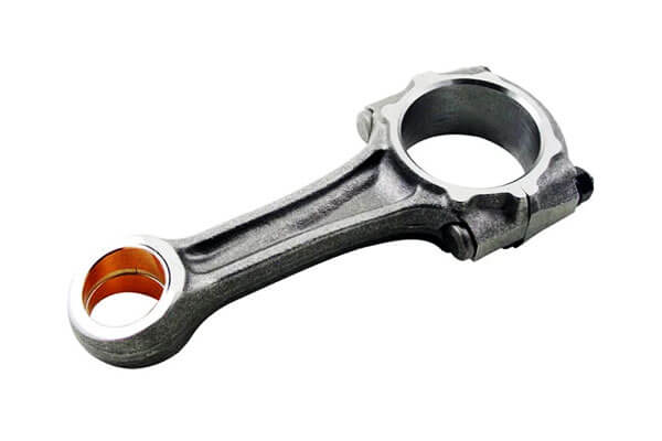
Typical Connecting-Rod Machining Process
A general process route may be:
Forging → heat treatment → datum machining → rough external machining → bore machining → cap separation → semi-finishing → precision boring/honing → final inspection
The sequence varies according to the connecting-rod design and whether conventional machining or fracture-split technology is used.
Rough machining establishes stable reference surfaces and removes the majority of the machining allowance.
Precision boring and honing are then used to achieve the final bore dimensions and geometric accuracy.
Bore Machining and Finishing
The big-end and small-end bores are generally machined through a sequence of rough boring, semi-finishing, and precision finishing.
Boring establishes accurate size and geometric form, while honing can further improve roundness, cylindricity, and surface characteristics where required.
For the big-end assembly, the relationship between the rod and cap is especially important.
After the cap is separated and reassembled, the finished bore must maintain the designed geometry and alignment.
Fracture-Split Connecting Rods
Fracture-splitting is widely used for suitable high-volume connecting-rod designs.
Instead of producing a conventional machined mating surface between the rod and cap, a controlled fracture is initiated along a predetermined region.
The resulting irregular fracture faces provide a highly individual mating interface, helping the cap and rod return to their original relative position during assembly.
This approach can offer:
- Accurate cap-to-rod location
- Reduced relative movement
- Elimination of some conventional machining operations
- Efficient high-volume production
- Consistent assembly positioning when properly controlled
However, fracture splitting requires carefully controlled material properties, notch geometry, fracture behavior, and process parameters. It is not suitable for every connecting-rod material or design.
The Core Principle of Connecting-Rod Machining
The fundamental challenge is to maintain the accurate spatial relationship between the big-end and small-end bores while preventing deformation of the relatively slender component.
This makes connecting-rod machining a classic example of low-rigidity precision manufacturing. Machine accuracy alone cannot guarantee the final result.
The process must simultaneously control datum selection, fixture loading, cutting force, material removal, heat treatment, bore finishing, and inspection.
In high-volume automotive production, the most effective process therefore combines rigid and repeatable fixturing with controlled machining parameters, automated measurement, and, where appropriate, fracture-split technology.
7. Comparison of the Six Typical Machining Parts
Although shafts, sleeves, housings, gears, pistons, and connecting rods have very different geometries, their process-planning logic can be compared systematically.
| Part Type | Primary Machining Challenge | Critical Features | Common Processes | Major Control Point |
| Shaft | Rotational accuracy and concentricity | Journals, shoulders, threads, keyways | Turning, grinding, spline machining | Coaxiality and runout |
| Sleeve | Bore accuracy and deformation | Bore, OD, end face | Drilling, boring, reaming, honing | Bore-to-OD relationship |
| Housing | Datum and hole-system accuracy | Mounting faces, bores, holes | Milling, boring, drilling, grinding | Position and geometric accuracy |
| Gear | Tooth geometry and heat-treatment distortion | Tooth profile, lead, pitch, bore | Hobbing, shaping, shaving, honing, grinding | Gear accuracy and runout |
| Piston | Functional profile and thermal geometry | Skirt, pin bore, ring grooves | Turning, boring, groove machining | Profile and positional accuracy |
| Connecting rod | Low rigidity and deformation | Small-end/big-end bores | Milling, boring, honing, fracture splitting | Bore alignment and center distance |
The table shows an important pattern: the machining method should follow the functional geometry of the part.
There is no universally superior machining process.
Turning is ideal for rotational surfaces, boring is essential for precision internal diameters, milling dominates complex prismatic surfaces, grinding provides high precision after heat treatment, and forming or fracture-based processes can reduce machining requirements for suitable high-volume components.
8. Conclusion
The six representative part types—shafts, sleeves, housings, gears, pistons, and connecting rods—provide a useful cross-section of mechanical machining practice.
Despite differences, the same fundamental principles appear again and again:
Correct datum selection → logical process sequencing → appropriate machining methods → effective deformation control → reliable inspection
This is the real foundation of machining process design.
The objective is not simply to remove material as quickly as possible.
A successful machining process must transform the blank into a component that meets its dimensional, geometric, functional, metallurgical, surface, and economic requirements consistently.
For engineers, process planners, and manufacturers, understanding these six typical part categories provides more than a list of machining methods.
It offers a practical framework for analyzing unfamiliar components and selecting a process route based on part structure, functional requirements, material behavior, accuracy, and production volume.
FAQs
What is the most challenging part to machine among these six types?
It depends on the precision grade, but generally gears and pistons present the highest process complexity.
Gears require specialized tooth profile machining and tight geometric tolerances, while pistons require precise control of complex curved profiles and multiple datum transfers.
Which process delivers the highest precision gear tooth quality?
Gear grinding produces the highest tooth profile accuracy and is the standard process for precision grade hardened gears.
It can correct distortion from heat treatment and achieve the highest AGMA or DIN accuracy grades.
Why is datum selection so critical in housing machining?
Housings have multiple interrelated hole systems and mating faces. All positional tolerances stack up from the primary datum.
Poor datum selection creates cumulative alignment error that directly degrades assembly fit and machine performance.
What is the benefit of fracture splitting for connecting rods?
Fracture splitting creates a perfectly matched, form-locking interface between the rod and cap.
This improves assembly accuracy, eliminates machining of the mating surface, reduces parts count, and increases big-end structural integrity.
What is the standard finish for bearing sleeve bores?
Most precision bearing bores are finished by honing, which produces excellent roundness, controlled surface texture, and consistent size.
For very high precision applications, bore grinding or superfinishing may be specified.

