1. Introduction
Lost-wax (investment) casting converts accurate sacrificial patterns—traditionally wax—into metal parts via a ceramic shell.
Its core strengths are: excellent surface finish, high dimensional accuracy, and the ability to cast complex geometries and high-performance alloys.
Process variants (wax grades, shell chemistry and core methods) let engineers trade cost vs fidelity and choose routes that work for stainless steels, copper alloys, irons, and — with special precautions — titanium and nickel superalloys.
2. Lost Wax Casting Process
Typical sequence (high level):

- Pattern: make wax (or castable resin) pattern(s) — single piece or tree/bunch.
- Assembly: attach patterns to runners/gating to form a cluster.
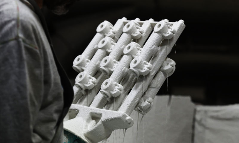
- Invest / shell build: dip assembly in binder slurry + stucco; repeat to build shell.
- Cure / dry: gel and partially dry shells between coats; final drying.
- Dewax: remove wax (steam or melt out).
- Burnout / firing: ramp to burn organics and stabilize shell.
- Pour: melt and pour metal into preheated shell.
- Shakeout & cleaning: remove shell, cut gates, clean.
- Post-process: heat treat, HIP (if required), machining, surface finish, inspection.
3. Pattern materials: low-, medium-, and high-temperature waxes
| Wax Type | Typical Melt Range (°C) | Primary Use | Advantages | Limitations |
| Low-temperature wax | ~45–80 °C | Jewelry, fine prototypes, small precision patterns | Easy injection/low energy dewax; fine finish | Soft — pattern creep; limited for large/complex trees |
| Medium-temperature wax | ~80–120 °C | General engineering: valve parts, pump components | Good dimensional stability and durability for tooling | Requires higher dewax energy; balanced properties |
| High-temperature wax / high-melting pattern materials | >120 °C (up to ~200 °C for specialized blends) | Large, heavy patterns; long cycle production; less pattern distortion | Better hot-strength and dimensional integrity; reduced pattern distortion | More difficult dewax/burnout; higher energy and tooling stress |
Notes & guidance
- Choose wax by part size, tooling life and expected shell/build sequence. Low-temp wax is great for fine detail and low-volume but suffers creep for long cycles or warm shop areas.
Medium temp is the workhorse for engineering casting. High-temp waxes (and engineered pattern polymers) are used where handling or long shell builds risk distortion. - Pattern additives: plasticizers, stabilizers, flow improvers and colorants affect injection behavior, dewax residue and burnout gas evolution—specify foundry-approved formulations.
4. Pattern production: tooling, injection wax, and additive patterns
- Injection molding: steel/aluminum dies for wax — low per-piece cost at volume with high surface quality. Tooling cost scale depends on complexity.
- 3D printed castable wax/resin patterns: SLA, DLP, material-jetting or castable wax printers eliminate tooling for prototypes and small runs.
Modern castable resins dewax cleanly and approach injection wax surface quality. - Pattern treeing and gating design: arrange patterns on a central sprue for efficient pouring and feeding; include sacrificial risers for shrink feed.
Use simulation for gating and feeding balance for large clusters.
5. Shell Systems: Silica-sol, Water-glass, and Hybrid shells
The shell system is the single most important variable that determines surface fidelity, thermal resistance, permeability/venting, vacuum compatibility and alloy suitability in lost-wax casting.
Three practical families are used in modern shops:
- Silica-sol (colloidal-silica) shells — the premium, high-fidelity route.
- Water-glass (sodium-silicate) shells — the economical, robust route for larger / steel/iron work.
- Hybrid shells — combine a fine, chemically resistant inner coat (silica-sol or zircon) with water-glass outer coats to balance cost and performance.
Silica-sol shells (colloidal silica)
What it is and how it works
Silica-sol shells use a colloidal suspension of sub-micron silica particles as the binder.
The first coats (very fine wash) use the colloid to carry ultrafine stucco that records detail; subsequent coats build thickness and are consolidated by drying and high-temperature firing (sintering) that produces dense, strong shells.

Key characteristics:
- Surface fidelity: best available — as-cast Ra commonly ~0.6–3 µm with fine wash.
- Thermal stability / firing: shells can be consolidated at 600–1,000°C (shop practice varies with stucco). High-temperature firing increases shell strength and thermal shock resistance.
- Vacuum/inert compatibility:excellent — silica-sol shells are compatible with vacuum and inert-atmosphere pours and are the usual choice for titanium, nickel and cobalt superalloys.
- Permeability control: can be tuned by stucco grading and firing to give controlled venting for high-value, tight castings.
- Contamination sensitivity:high — colloid stability is upset by ionic contamination (salts, metal fines) and organics; slurry and plant cleanliness are critical.
- Typical first-coat stucco: sub-10 µm fused silica, zircon or zirconia for reactive interfaces.
- Typical use cases: aerospace turbine components, superalloys, vacuum-poured titanium, medical implants, precision small parts.
Water-glass shells (sodium-silicate)
What it is and how it works
Water-glass shells use an aqueous sodium (or potassium) silicate solution as binder.
Coats gel to a silica-like network by CO₂ gassing or chemical hardeners (acid salts), producing a rigid ceramic shell when combined with graded refractory stucco.

Key characteristics:
- Surface fidelity: good for general engineering — as-cast Ra typically ~2.5–8 µm depending on wash and stucco.
- Firing: usually stabilized at ~400–700°C; shells are not sintered to the same extent as silica-sol systems.
- Vacuum compatibility:limited — not ideal for vacuum/inert pours or the most reactive alloys.
- Permeability / venting: generally good for steels/irons; permeability tends to be coarser than optimized silica-sol shells.
- Curing method:CO₂ gassing (rapid gelation) or acid hardeners — fast, robust set on the shop floor.
- Contamination sensitivity: moderate — ionic contamination affects setting and gel uniformity but water-glass is generally more tolerant than silica-sol.
- Typical first-coat stucco: fine fused silica; zircon can be used for improved surface protection.
- Typical use cases: valve bodies, pump housings, large steel/iron parts, marine hardware, general industrial castings.
Hybrid shells (silica-sol or zircon inner coat + water-glass outer coats)
What it is and how it works
A common economic compromise: a premium inner coat (silica-sol or zircon/zirconia wash) is applied first to capture detail and create a chemically resistant barrier, then water-glass outer coats are built to give bulk strength at lower cost.
Key characteristics:
- Surface fidelity & chemical barrier: inner silica-sol/zircon gives near-silica-sol surface quality and helps prevent metal-shell reactions at the metal interface.
- Cost & handling: outer water-glass coats reduce total silica-sol usage and make the shell more robust for handling and large sizes.
- Vacuum compatibility: improved vs pure water-glass (thanks to inner coat) but still not as ideal as full silica-sol shells — useful for many stainless and some nickel alloys if melting/pour atmospheres are controlled.
- Typical uses: valve bodies with high-quality wetted surfaces, medium-value turbine parts where some vacuum compatibility is needed, applications where cost vs performance must be balanced.
6. Core technologies
- Soluble cores (wax or polymer cores made to dissolve): produce internal passages (cooling channels); removed by hot water or solvent.
- Binder-fired ceramic cores (silica, alumina, zircon): stable at high temps for superalloys; require shell-core compatibility.
- 3D-printed cores: binder-jet or SLA ceramic cores enable complex internal geometries without tooling.
Design for cores must consider core support, venting, thermal expansion and chemical compatibility with molten metal.
7. Dewaxing, burnout & shell firing — practical schedules and control points

Dewaxing
- Steam/autoclave dewax: common for conventional wax trees. Typical surface temp 100–120 °C; cycle minutes to hours depending on wax volume and tree size.
- Thermal dewax / solvent melt: used for some polymers—use solvent recovery and controls.
Burnout / burnout schedule (typical engineering example)
- Ramp: slow up through 100–200 °C to remove moisture/wax residues (≤3–5 °C/min recommended for thick shells to avoid steam blistering).
- Hold 1: 150–250 °C (1–4 hours) to drive off low-boiling organics.
- Ramp 2: ~3 °C/min to 350–500 °C.
- Final hold: 4–8 hours at 350–700 °C depending on shell system and alloy. Silica-sol shells may be fired to 600–1000 °C for sintering/strength; water-glass shells commonly stabilized at 400–700 °C.
- Key controls: ramp rate, oxygen availability (avoid excessive oxidizing for reactive metal shells), and complete removal of organics to avoid gas evolution during pour.
Shell preheat before pour: shell preheat to 200–800 °C depending on alloy to minimize thermal shock and improve metal flow; e.g., stainless pours commonly 200–450 °C preheat; superalloys require higher depending on shell.
8. Pouring: melt practice, vacuum/inert options and pouring parameters
- Melting furnaces: induction or resistance; degassing/filtration and fluxing for cleanliness.
- Pour temperatures (typical):
-
- Aluminum alloys: 650–720 °C
- Copper alloys: 1000–1200 °C
- Steels: 1450–1650 °C
- Nickel superalloys: 1400–1600+ °C (alloy dependent)
- Vacuum and inert pouring: mandatory for titanium and highly reactive alloys; vacuum reduces oxidation and metal-shell reactions.
- Pour mode: gravity pour vs bottom-pour ladle vs vacuum assisted — choose to minimize turbulence and entrained gases. Use filters in gating for inclusion control.
9. Materials commonly cast & special considerations
- Stainless steels (300/400, duplex): good with both water-glass & silica-sol; control shell permeability and final preheat.
- Carbon & low alloy steels, ductile iron: well suited to water-glass shells; watch for scaling and shell erosion at high pour energies.
- Copper alloys (bronze, Cu-Ni): common; control superheat to avoid shell wash.
- Aluminum alloys: possible but often cheaper by other casting methods; ensure venting/permeability.
- Titanium & Ti alloys: reactive — prefer silica-sol shells, zircon/alumina first coats, vacuum melts, and inert atmospheres. Avoid water-glass unless barrier coats and specialist controls used.
- Nickel & cobalt superalloys: use silica-sol shells, high-temp firing and vacuum/inert handling where needed.
10. Typical dimensional, surface and tolerance capabilities
- Dimensional tolerance (typical as-cast): ±0.1–0.3% of nominal dimension (e.g., ±0.1–0.3 mm on 100 mm feature).
- Surface finish (Ra as-cast): silica-sol ~0.6–3.2 µm; water-glass ~2.5–8 µm.
- Linear shrinkage allowance: ~1.2–1.8% (alloy & foundry specify exact).
- Minimum practical wall thickness: jewelry/micro parts: <0.5 mm; engineering parts: 1.0–1.5 mm typical; structural thicker sections common.
- Repeatability: good foundry practice yields ±0.05–0.15% run-to-run on critical datums.
11. Common defects, root causes and remedies
| Defect | Symptoms | Typical root cause | Remedy |
| Gas porosity | Spherical pores | Dissolved H₂ or trapped dewax gases | Improve degassing, filtrations; control dewax/burnout; vacuum pour |
| Shrinkage porosity | Irregular cavities at hot spots | Poor feeding; insufficient risering | Rework gating, add chills, use risers, intensify holding pressure |
| Hot tears / cracks | Cracks during solidification | High restraint, sharp transitions | Add fillets, change section, modify gating, use chills |
| Shell cracking | Shell breaks pre-pour | Rapid drying, thick coats, poor cure | Slow drying ramps, thinner coats, improved CO₂ cure control |
Metal penetration / washout |
Rough surface, metal into shell | Weak first coat, high superheat | Improve first coat (fine stucco/zircon), reduce superheat, increase viscosity |
| Inclusions / slag | Non-metallics in casting | Melt contamination, poor filtration | Clean melt, use ceramic filters, skimming practice |
| Dimensional distortion | Out of tolerance | Pattern creep, thermal warping | Use high-temp wax, control pattern storage temp, improved shell rigidity |
12. Post-casting Processes
- Shakeout & ceramic removal: mechanical or chemical methods.
- Heat treatment: solution treatment, aging (T6), anneal — alloy dependent. Typical solution temps: Al alloys ~520–540 °C; steels higher.
- Hot Isostatic Pressing (HIP): reduces internal shrinkage porosity for fatigue-sensitive parts; typical HIP cycles depend on alloy (e.g., 100–200 MPa at 450–900 °C).
- Machining & finishing: critical bores, sealing faces machined to tolerance; polishing, passivation or coating applied as required.
- NDT & testing: hydrostatic, pressure, leak tests, X-ray/CT, ultrasonic, dye-penetrant, mechanical testing per spec.
13. Process control, inspection & qualification
- Shop QC metrics: slurry solids, viscosity, gel time, oven curves, dewax logs, burnout ramp charts, melt chemistry and degassing logs.
- Sample coupons: tensile, hardness & metallography coupons cast in gating for representative microstructure and mechanical properties.
- NDT sampling: radiography and CT scanning for critical components; specify acceptance levels for porosity (vol% or max defect size).
- Statistical process control (SPC): apply to critical inputs (wash solids, shell thickness, melt hydrogen) and outputs (dimensional variation, porosity counts).
14. Common Misconceptions & Clarifications
“Lost Wax Casting Is Only for High-Precision Parts”
False. Water glass-based lost wax casting is cost-effective for medium-precision parts (±0.3–0.5 mm) — 40% of automotive lost wax castings use this variant.
“Low-Temperature Wax Is Inferior to Medium-Temperature Wax”
Context-dependent. Low-temperature wax is cheaper and suitable for low-precision, high-volume parts (e.g., hardware) — medium-temperature wax is only necessary for tighter tolerances.
“Silica Sol Is Always Better Than Water Glass”
False. Water glass is 50–70% cheaper and faster for medium-precision applications — silica sol is only justified for aerospace/medical parts requiring ±0.1 mm tolerance.
“Lost Wax Casting Has High Scrap Rates”
False. Silica sol lost wax casting has a scrap rate of 2–5% (comparable to die casting) — water glass has 5–10% (still lower than sand casting’s 10–15%).
“3D Printing Makes Lost Wax Casting Obsolete”
False. AM is ideal for prototypes/low volume, but lost wax casting is 5–10x cheaper for medium-to-high volume (>1,000 parts) and handles larger parts (up to 500 kg).
15. Conclusion
The lost wax casting process remains a premier method for producing complex, high-fidelity metal components.
When you pair the right pattern material, shell chemistry and melt/atmosphere practice with disciplined process control, lost-wax casting reliably creates parts that would be difficult or impossible by other means.
Modern enhancements (3D printed patterns, hybrid shells, vacuum pouring and HIP) extend the process into new alloys and applications — but they also raise the need for careful specification, trialing and QA.
FAQs
Which shell system should I choose for titanium?
Silica-sol (with zircon/alumina first coat) + vacuum/inert melting and pouring. Water-glass is generally unsuitable without extensive barrier measures.
How fine can features be with lost-wax casting?
Features <0.5 mm are possible (jewellery/precision); in engineering parts aim for ≥1 mm for robustness unless proven by trials.
Typical surface finish I can expect?
Silica-sol: ~0.6–3.2 µm Ra; water-glass: ~2.5–8 µm Ra. Fine washes and polishing of wax dies improve finish.
When is HIP recommended?
For fatigue-critical, pressure-containing, or aerospace parts where internal porosity must be minimized — HIP can dramatically improve fatigue life.
Can I use 3D printed patterns instead of wax tooling?
Yes — castable resins and printed wax reduce tooling time and cost for prototypes/low volumes. Ensure resin dewax characteristics and shell compatibility are validated.

