1. Introduction
A gate valve is a linear, on/off valve designed to either fully open or fully close the flow of fluid through a pipeline.
It employs a sliding gate (or wedge) that moves perpendicular to the flow path, offering minimal obstruction when fully open and tight sealing when closed.
Unlike throttling valves, gate valves are not intended for flow regulation but for isolation purposes.
Historical Development and Evolution
Gate valves trace back to early steam applications in the 1800s.
As industrial systems grew in complexity and scale, gate valves evolved—from cast-iron bodies and handcrafted wedges to high-performance alloy designs with precision-machined seats.
Modern manufacturing and materials science have enabled valves that withstand extreme pressures (> 250 bar) and temperatures (–196°C to 600°C), serving demanding oil & gas, power, and chemical processes.
2. What Is a Gate Valve?
A gate valve is a full‑bore shut‑off valve that uses a metal gate (or wedge) to block fluid flow.
In its fully open position, the gate withdraws entirely from the flow path, creating a passage equal in diameter to the pipeline bore.

This “straight‑through” configuration minimizes flow resistance and pressure loss, making gate valves ideally suited for applications where maximum flow capacity and minimal ΔP are critical.
Gate valves are manufactured in sizes from DN 10 (¾”) to DN 2000 (80″) and pressure classes ranging from Class 125 (≈ 19 bar) up to Class 2500 (≈ 413 bar).
Key attributes:
- On/Off Service Only: Not intended for throttling; partial strokes can cause seat erosion.
- Bi‑Directional Isolation: Provides equally tight sealing whether flow is upstream or downstream.
- Visual Position Indication: Rising‑stem and OS&Y designs allow operators to see at a glance whether the valve is open or closed.
Principle of Operation
Gate-and-seat mechanics
The operation of a gate valve is based on the interaction between the gate and the seats within the valve body.
When the valve is closed, the gate descends and seats against two sealing surfaces (seats) in the valve body.
In wedge-type gates, the conical shape of the gate forces it tightly against the seats as it moves downward, creating a seal.
Parallel-type gates rely on the pressure of the fluid or an external force to press the gate against the seats.
When the valve is opened, the gate is lifted out of the flow path, allowing the fluid to pass through the valve with minimal obstruction.
Flow control characteristics
In the fully open position, gate valves offer a straight-through flow path, resulting in a very low-pressure drop.
This makes them ideal for applications where maintaining high flow rates with minimal energy loss is crucial, such as in long-distance pipelines.
However, gate valves are not suitable for throttling applications.
When partially open, the gate creates a narrow passage for the fluid, which can cause high-velocity flow, turbulence, and excessive wear on the gate and seats.
This can lead to noise, vibration, and a shortened valve lifespan. As a result, gate valves are primarily used for on-off service rather than for continuously regulating flow rates.
3. Design and Construction of Gate Valve
The reliability and longevity of a gate valve hinge on meticulous design of its components, judicious material selection, and proper end‑connection methods.
Key Components
| Component | Function & Characteristics |
| Body | Houses internal parts and sustains line pressure. Typically cast or forged; body wall thickness follows ASME B16.34 to withstand up to Class 2500 (≈ 413 bar). |
| Bonnet | Covers and seals the body chamber. Bonnet-to-body joint may be bolted, threaded, or welded. Provides access for maintenance. |
| Gate (Disc) | The moving barrier. Designs include solid wedge, flexible wedge (axial cuts to absorb thermal expansion), and split wedge (two independent halves for self‑alignment). |
| Seats | Precision‑machined surfaces on which the gate seals. May be integral (metal‑to‑metal) or replaceable soft rings (PTFE, nickel). |
| Stem | Transmits motion from actuator to gate. Commonly 20 MnV6 or stainless steel for corrosion resistance. Thread standards (e.g., Acme or trapezoidal) ensure smooth travel. |
| Packing & Gland | Sealing around the stem. Graphite or PTFE packings achieve leak rates ≤ 10⁻⁶ m³/s; gland nuts compress packing uniformly. Periodic re‑packing restores seal integrity. |
| Handwheel/Actuator | Converts manual or remote control inputs into gate movement. Electric actuators provide up to 10 000 Nm torque for DN > 300 mm or Class 1500+ valves. |
Materials Selection
Material choice is driven by pressure, temperature, fluid chemistry, and cost. Below is a summary of common materials and their service envelopes:
| Material | Typical Applications | Temperature Range | Corrosion Resistance |
| Cast Iron (EN 1561) | Water, low-pressure steam | –10 °C to 150 °C | Moderate; not suitable for acidic/alkaline media |
| Carbon Steel (A216 WCB) | Oil & gas, general industrial steam | –29 °C to 425 °C | Good; susceptible to CO₂/H₂S corrosion unless coated |
| Stainless Steel (304/316) | Food, pharmaceutical, seawater | –196 °C to 550 °C | Excellent; resists a broad spectrum of chemicals |
| Alloy Steels (WC6/CrMo) | High-temperature steam, petrochemical | 450 °C to 600 °C | High strength; resists creep and sulfidation |
| Duplex/Super Duplex SS | Offshore oil & gas, chlorides | –50 °C to 300 °C | Exceptional resistance to pitting and stress corrosion |
| Plastics (PVC/CPVC/PP) | Acids, caustics, low-temperature water | 0 °C to 65 °C | Good for strong acids/bases; limited temperature range |
End Connections (flanged, threaded, welding)
Flanged
Flanged connections are the industry standard for gate valves.
Each valve end features a flat, circular flange that mates to a matching flange on the pipeline via bolts and gaskets.
This arrangement delivers a leak‑tight seal capable of withstanding high pressures and temperatures, while also permitting rapid installation and removal for maintenance or inspection.
Threaded
Threaded ends—either internal (female) or external (male)—are common on small‑bore valves (typically ≤ DN 50). They offer quick, simple make‑up without the need for gaskets or bolting.
However, their service envelope is limited: thread connections can loosen or leak under cyclic loads, extreme temperatures, or high-pressure swings, and are therefore unsuitable for critical or high‑pressure systems.
Welded
Welding permanently fuses the valve to the pipeline—either via socket‑weld (for ≤ DN 50) or butt‑weld (for larger sizes).
This method produces an exceptionally strong, zero‑leak joint ideal for high‑pressure, high‑temperature, or safety‑critical services.
The trade‑off is maintenance complexity: removal typically requires cutting and re‑welding the pipeline.
Stem Variations: rising vs. non‑rising stem; outside screw & yoke (OS&Y)
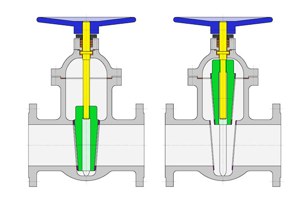
Rising‑Stem vs. Non‑Rising‑Stem
- Rising‑Stem: The stem thread engages the gate, so as the valve opens the stem visibly extends above the bonnet.
This provides an unambiguous, at‑a‑glance indication of valve position—valuable in large installations or where rapid status checks are required. - Non‑Rising‑Stem: The stem remains at a fixed height and turns within the bonnet; the gate moves internally.
This compact design suits confined spaces or overhead piping, eliminating clearance concerns and protecting the stem from external hazards.
Outside Screw & Yoke (OS&Y)
OS&Y valves are a subtype of rising‑stem design in which the screw threads remain external to the pressure boundary, supported by a welded yoke. Advantages include:
- Accessible Maintenance: Exposed threads stay clean and lubricated, simplifying packing replacement and lubrication.
- Clear Position Indication: The exposed screw travel directly corresponds to gate position.
- High‑Pressure Capability: Commonly specified for large‑diameter or Class 600+ installations where reliable, visible isolation is critical.
4. Types and Classification of Gate Valve
Gate valves are engineered in diverse configurations to suit varying pressure, temperature, and media characteristics.
Based on Body and Disc Design
Gate valves differ primarily in the geometry and construction of their disc (gate) and how that disc interacts with the body seats.

Solid (Rigid) Wedge Gate Valve
- Geometry: Single, tapered disc machined with a 3°–5° cone angle.
- Sealing Mechanism: Metal‑to‑metal contact as the wedged disc is forced into the matching tapered seats.
- Strengths:
-
- Exceptional durability in constant‑temperature services.
- Simplest design yields the fewest leak paths and the lowest manufacturing cost.
- Limitations:
-
- Susceptible to binding or jamming when faced with thermal expansion or seat misalignment; actuation torque can rise by up to 30 %.
- Not ideal for frequent thermal cycling.
Flexible Wedge Gate Valve
- Geometry: One‑piece disc with one or more axial slots (usually 1–2 cuts) allowing it to flex by 0.5–1 mm.
- Sealing Mechanism: Tapered faces maintain full contact even under differential expansion between disc and body.
- Strengths:
-
- Automatically compensates for seat misalignment or distortion from temperature swings (± 50 °C).
- Maintains uniform sealing pressure, reducing leakage risk under thermal cycling.
- Limitations:
-
- Slightly higher material and machining costs (approximately 10–15 % premium over solid wedges).
- Flexural fatigue must be considered in very high-cycle applications.
Split (Dual) Wedge Gate Valve
- Geometry: Two independent half-discs connected loosely by a spring, pin, or tie‑rod.
- Sealing Mechanism: Each half aligns independently to its respective seat, ensuring uniform metal‑to‑metal contact.
- Strengths:
-
- Tolerant of seat imperfections and misalignment up to 1 mm without compromising seal.
- Ideal for high‑pressure (Class 600–1500) and high‑vibration environments where rigid wedges may jam.
- Limitations:
-
- Increased part count and complexity; spare‑part inventory and maintenance time can double.
- Spring or pin components introduce additional potential wear points.
Parallel Slide Gate Valve
- Geometry: Flat, parallel faces on the disc; no inherent taper.
- Sealing Mechanism: External springs or system pressure push the disc onto the downstream seat; a machined shoulder often prevents over‑travel.
- Strengths:
-
- Uniform seating force across the entire disc face, regardless of gate position, reducing localized stress and wear.
- Well suited for abrasive or slurry services, as lower wedging forces minimize particle embedding and galling.
- Limitations:
-
- Requires auxiliary hardware (springs or pressure-balance ports), adding cost and potential leak paths.
- Sealing integrity depends on spring force or sufficient differential pressure; may not seal reliably at very low pressures.
Based on Pressure–Temperature Ratings
Gate valves must be specified to match both the maximum operating pressure and temperature of the system.

Standards define discrete “classes” or “ratings” that guarantee a valve’s pressure capability at a reference temperature (usually 38 °C), along with a permissible pressure–temperature envelope beyond that point.
Selecting the correct rating ensures safe, leak‑free performance under all expected service conditions.
Common Rating Standards
| Standard | Designation | Pressure @ 38 °C | Temperature Range¹ | Typical Materials |
| ANSI/ASME B16.34 | Class 150 | ≤ 19 bar | –29 °C to 425 °C² | WCB, CF8M, WC6 |
| Class 300 | ≤ 51 bar | –29 °C to 425 °C² | WCB, CF8M, WC6 | |
| Class 600 | ≤ 124 bar | –29 °C to 425 °C² | WCB, WC6, CrMo | |
| Class 900 | ≤ 196 bar | –29 °C to 550 °C³ | WC6, CrMo | |
| Class 1500 | ≤ 258 bar | –29 °C to 550 °C³ | WC6, CrMo, Alloy 625 | |
| Class 2500 | ≤ 413 bar | –29 °C to 550 °C³ | Alloy 625, Duplex SS | |
| ISO 5208 / DIN PN | PN 6 | ≤ 6 bar | 0 °C to 120 °C | Ductile iron, PVC |
| PN 10 | ≤ 10 bar | 0 °C to 120 °C | Ductile iron, PP | |
| PN 16 | ≤ 16 bar | –10 °C to 150 °C | Cast iron, WCB | |
| PN 25 | ≤ 25 bar | –10 °C to 200 °C | WCB, WC6 | |
| PN 40 | ≤ 40 bar | –10 °C to 225 °C | WC6, CrMo |
Special‑Purpose Gate Valves

Cryogenic Gate Valves
- Design Features: Extended bonnets (up to 2× valve height) to isolate packing from –196 °C cryogen; low‑temperature alloys (A351 CF8M, ASTM A182 F304L).
- Key Data: Leakage ≤ 1 × 10⁻7 m³/s; thermal contraction allowances up to 2 mm.
- Use Cases: LNG processing, industrial gas distribution.
High‑Temperature Gate Valves
- Design Features: WC6 or CrMo alloy bodies, graphite/metallic packings rated to 600 °C, optional steam‑heated jackets.
- Key Data: Creep strength ≥ 30 MPa at 550 °C; seat leakage Class IV (≤ 0.1 % capacity) at elevated temps.
- Use Cases: Superheated steam lines, refinery furnaces.
Abrasive and Slurry‑Service Valves
- Design Features: Hard-faced trims (stellite, WC–Co overlays), ceramic/PU linings, sacrificial seat rings replaceable in under one hour.
- Key Data: Erosion rates < 0.05 mm/year at 10 m/s slurry velocity; life improvement > 5× over unenforced trims.
- Use Cases: Mining tailings, pulp & paper stock lines, sand-laden water.
Corrosion‑Resistant / Lined Valves
- Design Features: PTFE/FEP linings up to 3 mm thick, stainless-steel or Hastelloy wetted parts, double-lip packing to handle aggressive chemicals.
- Key Data: Compatibility with 98 % H₂SO₄, 50 % NaOH; leak rates ≤ 1 × 10⁻6 m³/s.
- Use Cases: Acid/caustic dosing, chlorine service, pharmaceutical CIP lines.
Pressure‑Balanced Gate Valves
- Design Features: Internal bypass channels equalize pressure across disc; balanced disc designs reduce unbalanced closing forces by 60–80 %.
- Key Data: Actuation torque reduction from 5 000 Nm to 1 000 Nm on a DN 600 Class 900 valve.
- Use Cases: Large-diameter water mains, high-pressure hydrocarbon pipelines.
5. Gate Valve Performance Parameters
Gate‑valve selection and sizing hinge on three key performance metrics: how much flow they pass (Cv and pressure drop),
how tight they seal (leakage class), and how much force or torque is required to operate them (actuation requirements).

Pressure Drop and Flow Coefficient (Cv)
Flow Coefficient (Cv):
Defined as the number of U.S. gallons per minute (gpm) of water at 60 °F that will pass through the valve with a 1 psi pressure drop.
Typical Cv Values:
| Valve Size (DN/in) | Kv (m³/h) | Cv (gpm/psi^½) |
| DN 50 (2″) | 50–70 | 60–85 |
| DN 100 (4″) | 200–240 | 240–290 |
| DN 200 (8″) | 800–1 000 | 960–1 200 |
| DN 300 (12″) | 2 500–3 000 | 3 000–3 600 |
Pressure Drop:
Gate valves are full‑bore, so the head‑loss coefficient (K) in fully open position is very low—typically 0.03–0.08.
For example, a DN 100 valve passing 20 m³/h of water yields ΔP ≈ 0.05 bar. Low ΔP minimizes pumping energy and operational costs in large pipeline systems.
Leakage Rates and Tightness Class
ANSI/FCI 70‑2 Leakage Classes:
| Class | Maximum Leakage (% of valve capacity per minute) |
| Class I | ≤ 10 % |
| Class II | ≤ 1 % |
| Class III | ≤ 0.1 % |
| Class IV | ≤ 0.01 % |
| Class V | ≤ 0.001 % |
| Class VI | ≤ 0.00001 % |
- Class IV–VI valves are used for critical services (e.g., steam isolation, toxic or hazardous fluids).
- API 598 Test:
-
- Shell test: Valve body pressurized to 1.5× rated pressure, no leakage permitted.
- Seat test: Valve closed against rated pressure (upstream side), with allowable leakage per ANSI/FCI class (water or air).
Soft-Seated vs. Metal-Seated:
- Soft seats (PTFE, elastomers) often achieve Class VI tightness at low-to-moderate temperatures (< 200 °C).
- Metal seats rely on precise machining and line pressure to seal, typically Class IV in high-temperature service.
Operating Torque and Actuation Methods
- Manual Operation (Handwheel):
-
- Required torque increases with valve size, pressure class, and seat tightness.
- Typical Manual Torques:
| Valve Size (DN) | Class 150 Torque (Nm) | Class 600 Torque (Nm) |
| DN 50 | 15–30 | 30–60 |
| DN 200 | 150–250 | 300–450 |
| DN 600 | 800–1 200 | 2000–3000 |
- Electric Actuators:
-
- Provide precise control and torque up to ~ 10 000 Nm for large‑diameter or high‑pressure valves.
- Features include torque/position feedback, variable speed, and integration with DCS/SCADA.
- Pneumatic Actuators:
-
- Use compressed air (4–8 bar supply) to drive a piston or diaphragm, delivering high-speed operation and torques up to ~ 5 000 Nm.
- Common in fail-safe designs (spring‑return) for emergency shut‑off.
- Hydraulic Actuators:
-
- Employ incompressible fluid to generate very high torques (5 000–20 000 Nm) and rapid cycling under extreme conditions.
- Suited for remote or offshore installations where electric or air power may be limited.
6. Applications Across Industries
Gate valves’ robust on/off isolation, bi‑directional sealing, and minimal flow resistance make them indispensable across a broad spectrum of process industries.

Oil & Gas
Upstream:
- Wellhead Isolation: Gate valves (DN 50–DN 150; Class 1500–2500) provide positive shut‑off on Christmas trees and choke manifolds, handling pressures up to 345 bar and sour service (H₂S) conditions.
- Drilling Fluid Control: Sizes DN 25–DN 100 with flexible‑wedge discs regulate mud returns and protect pumps from backflow.
Midstream:
- Pipeline Blocks: Large‑bore DN 600–DN 1200 Class 600 valves isolate 20–50 km pipeline sections for maintenance or pigging.
Valve Cv often exceeds 3 000 to accommodate crude oil flows of 10 000 m³/h. - Compressor Stations & Metering Skids: Class 900–1500 valves withstand cyclic pressures (up to 100 cycles/day) and temperatures from –40 °C (winter) to +50 °C (summer).
Downstream:
- Refinery Process Units: Gate valves with corrosion‑resistant trims (Hastelloy C‑276, Monel) isolate high‑temperature (400 °C) reactor feeds and naphtha stabilizer bottoms.
- LNG Terminals: Cryogenic gate valves (extended bonnets, soft-seat options) operating at –162 °C ensure leak‑free isolation during transfer and storage.
Power Generation
Steam Service:
- Boiler Isolation: Gate valves (DN 100–DN 500; Class 600–900; WC6/CrMo body, graphite packing) handle 100–160 bar steam at 520 °C, providing safety‑critical shut‑off for burner controls and superheater loops.
- Turbine Bypass & Drain Lines: High‑integrity Class 1500 valves isolate emergency bypass networks; quick action pneumatic actuators close in under 5 seconds to protect turbines during trip events.
Cooling Water & Condensate:
- Condenser Isolation: DN 300–DN 800 Class 150–300 cast‑iron or carbon‑steel gate valves regulate flows of 5 000–15 000 m³/h at 25–40 °C.
- Maintenance Bypass: Flanged‑end gate valves enable condenser tube bundle cleaning without grid outages.
Water and Wastewater Treatment
Raw Water Intake:
- Screen Isolation: Large‑diameter (DN 800–DN 2000) ductile‑iron gate valves control flows of 10 000–30 000 m³/h from reservoirs, with Class 150–300 ratings at up to 16 bar.
- Pump Station Isolation: DN 150–DN 400 valves protect multistage pumps; resilient-seated options provide Class VI shut‑off to prevent cross‑contamination.
Wastewater & Effluent:
- Sludge Lines: Abrasion‑resistant trims (tungsten‑carbide overlays) in DN 100–DN 300 valves endure slurries with 10–30 % solids and velocities up to 3 m/s.
- UV Disinfection Bypass: DN 50–DN 150 plastic-lined (PVC/CPVC) gate valves resist chlorine and UV lamp coolant chemicals at ambient temperatures.
Chemical and Petrochemical Processing
Corrosive Services:
- Acid/Alkali Lines: PTFE‑lined gate valves (DN 15–DN 200; PN 16–PN 40) handle 98 % H₂SO₄ and 50 % NaOH at 80 °C, achieving leak rates ≤ 1 × 10⁻⁶ m³/s.
- Chlorine & Chlorosulfonic Acid: Hastelloy C‑276 trims and double‑lip graphite packing maintain integrity at 120 °C and 20 bar.
Hydrocarbon Processes:
- Reaction Feed Isolation: Stainless‑steel Class 600 valves isolate C₄/C₅ feedstocks into reactors at 200 °C, minimizing vapor leakage and environmental emissions.
- Glycol Regeneration Units: Flexible‑wedge Class 300 valves in DN 50–DN 150 sizes handle 200 °C rich glycol with entrained solids.
7. Advantages & Disadvantages of Gate Valves
Advantages
- Minimal Pressure Loss
When fully open, the gate retracts completely, offering a straight‑through flow path with head‑loss coefficients as low as 0.03–0.08.
This translates to negligible ΔP, reducing pumping energy and operating costs in high‑flow systems. - Positive, Bi‑Directional Shut‑Off
Wedge‑type gates (solid, flexible or split) generate metal‑to‑metal contact pressure
that increases with line pressure, delivering ANSI/FCI Class IV–VI tightness in both flow directions—essential for safe isolation during maintenance or emergencies. - Broad Media Compatibility
Available in materials from cast iron and carbon steel to duplex stainless and special alloys, gate valves accommodate liquids, gases, and slurries across a wide pH and temperature spectrum (–196 °C to +600 °C). - Scalable Size and Rating
Manufactured from DN 10 to DN 2000 and rated ANSI Class 150 through 2500 (or PN 6–PN 40), gate valves suit everything from small instrumentation lines to large‑bore pipeline block valves. - Durability & Low Lifecycle Cost
With simple internals (8–12 major parts), flanged ends for easy access, and replaceable seats,
properly maintained gate valves can exceed 20 years of service in intermittent‑duty isolation roles.

Disadvantages
- Not Intended for Flow Regulation
Partial opening creates a narrow slot that accelerates fluid, causing turbulence, vibration, and accelerated seat/gate erosion—Cv can drop by up to 30 % after repeated throttling cycles. - Slow Operation & High Torque
Large or high‑pressure valves may require 20–60 turns to stroke fully, and closing torque can exceed several thousand Nm—necessitating gearboxes or powered actuators for rapid or remote actuation. - Bulky Footprint
Especially in rising‑stem or OS&Y designs, gate valves demand significant vertical clearance (up to 400 mm stem travel) and can weigh over a tonne in DN ≥ 600 mm sizes, increasing structural support requirements. - Higher Upfront Cost for Specialty Designs
Special alloys, flexible‑wedge or split‑wedge trims, and high‑integrity seats (soft or metal) command premiums of 10–30 % over simpler valve types, though often offset by reduced maintenance and longer service life.
8. Installation, Operation, and Maintenance
Installation & Alignment
- Inspection & Orientation: Verify valve and internals are damage‑free and clean. Install with flow arrow matching pipeline direction.
- Flanged Ends: Align faces parallel (< 0.5 mm), use a criss‑cross torque pattern on bolts.
- Threaded/Welded Ends: Apply appropriate sealant on threads; engage certified welders for butt‑ or socket‑weld joints.
- Support: Brace piping near the valve (within 1–1.5× valve diameter) to prevent body stress and misalignment.
Start‑Up, Shut‑Down & Throttling
- Slow Cycling: Open/close in 1–2 minutes (small valves) or 3–5 minutes (large) to avoid water hammer and seat impact.
- Full Stroke Only: Always operate gate valves fully open or closed—never throttle. For flow control, install a globe or control valve in series.
- Pressure Equalization: On high‑differential lines, use a bypass or equalizing valve to balance pressure before cycling.
Inspection & Troubleshooting
- Visual Checks: Monthly inspect for leaks at packing, bonnet, and ends.
- Torque Monitoring: Note any > 10 % increase—indicates seat wear, debris, or corrosion.
- Packing Service: Retorque gland nuts to spec; replace packing at first sign of seepage or degradation.
- Common Remedies:
-
- Leakage: Lap or machine seats; renew packing.
- Sticking Gate: Flush debris, cycle valve, inspect for corrosion.
- High Torque: Clean/lubricate stem threads; realign seats or replace worn parts.
Life‑Cycle Cost & Reliability
- Cost Breakdown: Initial purchase≈ 40%, installation≈ 10%, maintenance≈ 30%, downtime≈ 20%.
- Longevity & ROI: Though upfront costs may be higher, properly specified gate valves often outperform alternatives over 15–20 years in isolation service—especially with preventive maintenance and quality materials.
9. Standards, Codes & Regulatory Compliance
Gate‑valve design, manufacture, testing, and documentation must conform to recognized standards and regulations to ensure safety, reliability, and legal compliance.
International Standards
- ASME B16.34 “Valves—Flanged, Threaded, and Welding End”
Defines pressure–temperature ratings, materials, dimensions, tolerances, marking, and inspection requirements for gate (and other) valves in Classes 150–2500. - API 600 “Steel Gate Valves—Flanged and Butt‑Welding Ends”
Specifies requirements for metal‑seated, bolted‑bonnet steel gate valves used in oil, gas, and petrochemical service, including materials, design, inspection, and testing. - ISO 5208 “Industrial Valves—Pressure Testing”
Standardizes shell, seat, and backseat test procedures and allowable leakage rates for different valve classes (A–F), ensuring consistent performance verification worldwide.
Regional & Industry Codes
- PED (2014/68/EU)
European Pressure Equipment Directive mandates essential safety requirements, conformity assessment procedures, and CE marking for pressurized equipment above 0.5 bar, including gate valves. - ASME B31.3 “Process Piping”
Governs design, fabrication, assembly, and inspection of piping systems in chemical, petroleum, and related industries; references valve standards for pressure integrity and material compatibility. - API 6D “Pipeline Valves”
Covers design, testing, and documentation for valves used in pipeline transport of oil, gas, and hydrocarbons, with additional requirements for fugitive emissions and cycle testing. - NACE MR0175/ISO 15156
Specifies materials and corrosion controls for sour service (H₂S environments), mandating qualified alloys and hardness limits to prevent sulfide stress cracking.
10. Comparison with Other Valves
| Feature | Gate Valve | Globe Valve | Ball Valve | Butterfly Valve |
| Flow Resistance | Very low (K ≈ 0.03–0.08) | Moderate (K ≈ 5–10) | Very low (K ≈ 0.05–0.1) | Low–moderate (K ≈ 0.2–0.5) |
| Throttling | Not recommended | Excellent | Fair (cavitation risk) | Good (but non‑linear Cv) |
| Shut‑off Tightness | Class IV–VI (metal/soft seats) | Class IV–V (metal seats) | Class VI (soft seats) | Class IV–VI (depending on disc) |
| Bi‑directional | Yes | No | Yes | Yes |
| Operation Speed | Slow (20–60 turns) | Slow (15–40 turns) | Very fast (¼–½ turn) | Fast (¼–½ turn) |
| Size Range | DN 10–DN 2000+ | DN 10–DN 800 | DN 2–DN 300 | DN 50–DN 2000 |
| Pressure Ratings | ANSI 150–2500 / PN 6–PN 40 | ANSI 150–900 / PN 6–PN 40 | ANSI 150–600 / PN 6–PN 25 | ANSI 150–600 / PN 6–PN 40 |
| Cost (per DN) | Moderate | High | High | Low |
| Maintenance | Moderate (packing, seats) | High (many parts) | Low (few parts) | Low (few parts) |
| Footprint & Weight | Large and heavy in big sizes | Bulky | Compact | Compact |
11. Conclusion
Gate valves remain vital components in fluid-handling systems worldwide due to their robust construction, tight shut‑off capability, and versatility across pressure and temperature regimes.
By understanding the nuances of design, material selection, and maintenance best practices—and by adhering to industry standards—engineers can optimize valve performance and longevity.
As digital integration, advanced materials, and additive manufacturing reshape the industry, the gate valve will continue to evolve, underpinning the next generation of safe, efficient, and reliable process systems.
DEZE: High-Precision Valve Casting Solutions for Demanding Applications
DEZE is a specialized provider of precision valve casting services, delivering high-performance components for industries that require reliability, pressure integrity, and dimensional accuracy.
From raw castings to fully machined valve bodies and assemblies, DEZE offers end-to-end solutions engineered to meet stringent global standards.
Our Valve Casting Expertise Includes:
Investment Casting for Valve Bodies & Trim
Utilizing lost wax casting technology to produce complex internal geometries and tight-tolerance valve components with exceptional surface finishes.
Sand Casting & Shell Mold Casting
Ideal for medium to large valve bodies, flanges, and bonnets—offering a cost-effective solution for rugged industrial applications, including oil & gas and power generation.
Precision Machining for Valve Fit & Seal Integrity
CNC machining of seats, threads, and sealing faces ensures every cast part meets dimensional and sealing performance requirements.
Material Range for Critical Applications
From stainless steels (CF8M, CF3M) to duplex and high-alloy materials, DEZE supplies valve castings built to perform in corrosive, high-pressure, or high-temperature environments.
Whether you require custom-engineered control valves, gate valves, check valves, or high-volume production of industrial valve castings, DEZE is your trusted partner for precision, durability, and quality assurance.