
1. Introduction
CNC Milling sits at the heart of modern machining, enabling shops to shape everything from aerospace components to automotive molds.
Selecting the right cutter and strategy not only influences part quality but also impacts cycle time, tool life, and overall cost.
In particular, face milling and end milling represent two foundational approaches, each with distinctive mechanics, advantages, and limitations.
By understanding their key differences, engineers can optimize material removal rates, surface finish, and dimensional accuracy.
2. What Is Face Milling?
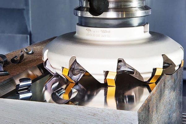
Face milling stands as a cornerstone of high-volume material removal and planar surfacing in modern CNC operations.
By orienting the cutter’s axis of rotation perpendicular to the workpiece, face mills engage multiple inserts simultaneously, producing wide, flat surfaces with high efficiency.
Definition and Fundamental Mechanics
In face milling, the tool’s peripheral teeth and cutter face both remove material. Typically, the cutter body spans 50 mm to 250 mm in diameter, housing 8–16 indexable inserts.
As the spindle rotates at 1000–3000 RPM, the cutter skims the surface with a shallow axial depth of cut (Ao ≈ 1–3 mm) and a heavy radial engagement (re ≈ 30–60% of diameter).
This combination maximizes the metal removal rate (MRR)—often reaching 500–800 cm³/min in mild steel—while maintaining surface integrity.
Typical Cutter Geometries
Most face mills use indexable insert heads, allowing quick tool changes and customizable cutting edges. Common geometries include:
- Square or round inserts (8–12 mm inscribed circle) for general milling
- High-feed inserts with reduced lead angles (10–20°) to boost MRR
- Positive-geometry inserts for low cutting forces and fine finish
Spindle connections usually employ robust tapers (CAT 50 or HSK 100) to minimize runout (< 3 µm) and ensure stability under heavy cut loads.
Cutting Kinematics
Face milling kinematics emphasize:
Axial engagement (Ao):
- Controls cut thickness per pass
- Typical range: 1–3 mm for roughing, 0.2–0.5 mm for finishing
Radial engagement (re):
- Dictates the cutter width in cut
- Often set to 30–60% of the cutter diameter for roughing
Feed direction:
- Conventional milling (climb) enhances surface finish but may increase tool wear
- Climb milling (down) reduces cutting forces at the expense of tool life
Balancing Ao, re, and feed per tooth (fz ≈ 0.05–0.2 mm) optimizes chip load and heat dissipation.
Features of Face Milling
- Large Diameter Cutters:
Wide heads (up to 250 mm) deliver high MRR and cover broad surfaces quickly. - Shallow Axial, Heavy Radial Cuts:
Spreading the cut over many inserts reduces per-insert load, extending tool life. - Surface Finish & Tolerances:
With a finishing pass (Ao ≈ 0.5 mm, fz ≈ 0.05 mm), shops achieve Ra 1.6–3.2 µm and flatness within ±0.02 mm over 300 mm. - Machine & Tooling Needs:
Requires rigid mills with 40–60 kW spindles, high-flow coolant, and precise toolholders (runout < 3 µm).
Pros of Face Milling
- Maximized Metal Removal:
MRR can exceed 700 cm³/min in steel, reducing roughing cycles by up to 50%. - Superior Flatness:
Large cutting diameter eliminates parting lines and yields planar surfaces with minimal passes. - Efficient Chip Evacuation:
Wide flute geometry and high-speed chips clear quickly, preventing recutting and heat buildup. - Lower Cutting Forces per Tooth:
Spreading load over 8–16 inserts decreases individual chip thickness and insert wear.
Cons of Face Milling
- Poor Vertical Wall Access:
Cutter geometry limits the ability to machine narrow slots or deep pockets—end mills handle those features. - Overhang Constraints:
Long tool extensions (L/D > 2:1) introduce deflection and chatter, especially in slender cavities. - Potential for Chatter:
High radial engagement on less rigid machines can excite spindle or workpiece resonances. - Insert Changeover Downtime:
Each indexing stop takes ~30–60 seconds, adding non-cutting time in long runs.
Applications of Face Milling
- Plate Surfacing & Deck Milling:
Leveling large castings or beds with planarity better than 0.02 mm over 300 mm. - Heavy Roughing:
Removing 3–5 mm per pass in castings and forgings before finishing. - Die & Mold Fly Cutting:
Light skim passes (Ao ≈ 0.5 mm) for block‐level planarization ahead of precision milling. - Preliminary Skim Passes:
Preparing surfaces for end-milling features by removing millimeter-scale stock.
3. What Is End Milling?
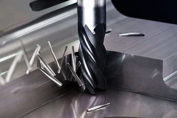
End milling represents one of the most versatile operations in modern CNC machining.
Unlike face milling, where the cutter’s axis stands perpendicular to the workpiece, end milling aligns the tool’s axis parallel (or at a slight angle) to the surface.
As a result, end mills engage material both at their periphery and at their tip, enabling plunging, slotting, and contouring in a single toolpath.
Definition and Core Cutting Principles
End mills remove material by rotating a multi-flute cutter and translating it along defined toolpaths.
Machinists can plunge the cutter into the workpiece, then move it laterally for slotting or profiling. Key parameters include:
- Radial engagement (ae): percentage of tool diameter engaged, from 5% (light finishing) up to 100% (full slotting).
- Axial depth of cut (ap): ranges from 0.5 mm in fine finishing to 10–25 mm in roughing passes.
- Feed per tooth (fz): typically 0.02–0.15 mm/tooth, depending on tool diameter and material.
By varying these, operators balance material removal rate (MRR)—often 200–400 cm³/min in steel—with tool life and surface finish requirements.
Typical Cutter Geometries
End mills come in a wide variety of shapes to suit different tasks:
- Square End Mills: Flat bottom for sharp corners and 2D profiles; diameters from 2 mm to 32 mm.
- Ball End Mills: Rounded tip for smooth 3-D contours; common in die and mold machining with diameters of 4–20 mm.
- Corner Radius End Mills: Built-in fillet on the corner, combining strength and finish; radii from 0.5 mm to 3 mm.
Additionally, specialty types include micro-end mills (diameters <2 mm) for fine corridors and roughing end mills with serrated flutes to break chips and boost MRR.
Cutting Kinematics
End milling’s cutting action depends on tool orientation and toolpath:
- Plunge Cutting: Operator plunges the tool vertically into the workpiece (ap up to the full tool length), then transitions to lateral movement.
- Slotting: The cutter moves along a path with 80–100% radial engagement, creating slots in a single pass.
- Profiling/Contouring: With light radial engagement (5–30%), the cutter follows complex 2-D or 3-D paths, shaping pockets and contours.
By coordinating spindle speed (500–10000 RPM, depending on diameter) with feed rates, machinists maintain stable chip loads and avoid tool deflection.
Features of End Milling
- Versatile Depth Control: You can adjust both axial and radial depths across a broad range, adapting to roughing and finishing in one tool type.
- Slotting and Pocketing: End mills excel at creating slots down to 0.5 mm width (with micro tools) and pockets up to 50 mm deep.
- Contouring Complex Shapes: Ball and corner-radius end mills produce smooth transitions on 3-D surfaces, with scallop heights under 0.02 mm.
- Roughing & Finishing: Roughing variants handle ap >10 mm and ae >50%, while polished flutes on finishing cutters achieve Ra 0.4–1.6 µm.
Pros of End Milling
- 3-D Contour Access: End mills carve intricate geometries—like turbine blade profiles or medical implant surfaces—without secondary setups.
- High Vertical Accuracy: Tight tolerances (±0.01–0.02 mm) on walls and features ensure proper component fit.
- Controlled Chip Thickness: By limiting AE to <30%, shops reduce cutting forces and achieve consistent tool wear.
- Wide Tool Selection: Diameters from 0.5 mm (micro-machining) up to 50 mm support a vast array of materials and applications.
Cons of End Milling
- Lower MRR vs. Face Milling: Even aggressive roughing end mills top out around 300–400 cm³/min, about half of what face mills achieve.
- Higher Forces per Tooth: Deep cuts concentrate loads on individual flutes, risking edge chipping, especially in carbide tools with small diameters.
- Risk of Tool Deflection: Long-reach end mills (L/D > 4:1) deflect under load, causing dimensional error or chatter.
- Complex Toolpath Programming: Generating efficient slotting, trochoidal, or 3-axis contours demands advanced CAM strategies and cycle optimization.
Applications of End Milling
- Precision Slotting & Pocketing: Machining keyways, T-slots, and internal cavities to ±0.02 mm.
- 3-D Surface Finishing: Generating smooth mold and die contours with ball-nose tools, achieving Ra <0.8 µm.
- Aerospace Feature Engraving: Milling cooling holes, flute patterns, and text on engine components with micro-end mills.
- Corner Rounding & Chamfering: Producing fillets and chamfers in one pass, eliminating secondary edge breaks.
4. Face vs. End Milling: How to Choose
Selecting between face and end milling depends on several interrelated factors.
By evaluating part geometry, material removal goals, surface and tolerance requirements, and machine capability, you can determine the optimal strategy—or even combine both methods—to maximize efficiency and part quality.
Decision Criteria
Part Geometry
- Flat, expansive surfaces (e.g. decks, flanges) naturally suit face milling.
- Slots, pockets, and 3-D contours require end milling for precise access.
Required Flatness & Finish
- Face mills deliver flatness within ±0.02 mm over 300 mm spans and roughness of Ra 1.6–3.2 µm.
- End mills achieve tighter localized features—vertical walls to ±0.01 mm and surface finishes down to Ra 0.8 µm on small areas.
Material Removal Rate (MRR)
- Face milling roughs 500–800 cm³/min in steel with large-diameter cutters.
- End milling tops out around 300–400 cm³/min even with roughing end mills.
Machine Rigidity & Spindle Power
- Heavy face milling requires rigid machines (40–60 kW spindles, CAT 50/HSK 100 tapers).
- End milling—especially micro or long-reach jobs—demands high-speed spindles (10 000–20 000 RPM) and minimized tool overhang.
Face Milling vs. End Milling — Comparative Table
| Category | Face Milling | End Milling |
|---|---|---|
| Primary Function | Machining large, flat surfaces | Machining slots, pockets, contours, and 3D features |
| Cutting Surface | Bottom of the cutter (axial engagement) | Bottom and sides of the cutter (axial + radial engagement) |
| Typical Cutter Geometry | Large diameter cutters with indexable inserts (Ø50–250 mm) | Solid carbide or HSS end mills (Ø3–50 mm), ball nose, corner radius |
Material Removal Rate (MRR) |
High (up to 800 cm³/min in steel) | Moderate (up to 400 cm³/min) |
| Feed per Tooth (Fz) | 0.1–0.3 mm/tooth | 0.02–0.15 mm/tooth |
| Surface Finish Achievable | Ra 1.6–3.2 µm | Ra 0.8–1.6 µm in finishing applications |
| Strengths | Excellent surface flatness, high removal rates, good chip evacuation | Access to complex features, high precision on small parts |
| Weaknesses | Cannot machine vertical walls or deep cavities; risk of chatter on long overhangs | Lower removal rates; risk of tool deflection at high aspect ratios |
| Common Applications | Deck milling, block surfacing, heavy plate roughing | Slotting, pocketing, profile milling, 3D mold finishing |
| Machine Requirements | High-torque, rigid machines for wide cutter engagement | High-speed spindles; capable of complex 3-axis or 5-axis movements |
| Tool Life Considerations | Insert wear; needs regular indexing or replacement | End mill breakage or chipping, especially in long-reach conditions |
Best-Practice Guidelines for Hybrid Strategies
- Stage 1 – Roughing with Face Mill: Remove 70–80% of stock at shallow axial and heavy radial cut.
- Stage 2 – Semi-Finishing Pass: Use a medium-diameter end mill (ae ~30%, ap ~2 mm) to trim corners and walls.
- Stage 3 – Finishing Pass: Employ a fine end mill (fz <0.05 mm, ap ~0.5 mm) for 3-D contours and tight tolerances.
- Optimize Toolpath: Apply adaptive clearing for end mills to maintain constant chip load and minimize tool wear.
- Monitor Vibrations: Adjust Ae and Fz to avoid chatter, especially on long-reach setups.
5. Conclusion
Face and end milling each serve crucial roles in modern machining.
Face milling maximizes material removal and flat-surface quality, while end milling unlocks 3D geometry and tight features.
By evaluating part design, MRR targets, and machine capabilities, engineers can deploy the optimal strategy—or a hybrid sequence—to achieve efficient, high-quality production.
Moving forward, innovations like high-feed face mills and micro-end mills continue to extend the capabilities of both methods, ensuring their relevance in high-mix, low-volume, and mass-production environments alike.
DEZE is the perfect choice for your manufacturing needs if you need high-quality CNC milling services.

