1. INNGANGUR
Skilvirk vökvastjórnun fer eftir því að velja rétta lokann fyrir verkið. Þar af leiðandi, verkfræðingar treysta á samanburðartöflur fyrir lokastærð til að þýða á milli mismunandi staðla, bera saman víddargögn, og staðfesta eindrægni.
Í þessum kafla, við skýrum umfang greinarinnar, undirstrika hvers vegna nákvæm ventustærð skiptir máli, og skilgreina hvað ventlastærðarsamanburðartafla er - og hvers vegna hún reynist svo gagnleg í daglegu starfi.
- Tilgangur og umfang: Við stefnum að því að útbúa ferli, vélrænt, og lagnaverkfræðingar með yfirgripsmikla leiðbeiningar um að búa til og nota samanburðartöflur fyrir lokastærð.
- Mikilvægi nákvæmrar stærðar: Misstórir lokar geta valdið allt að a 15% lækkun á skilvirkni ferlisins, leiða til ótímabærs slits, eða jafnvel framkalla kerfisbilanir. Aftur á móti, rétt stórar lokar hámarka flæði, draga úr orkunotkun, og lengja endingu búnaðar.
- Yfirlit yfir samanburðartöflur: Í kjarna þess, samanburðartafla fyrir lokastærð stillir saman nafnpípustærð (NPS) eða Nafnþvermál (DN) tilnefningar með raunverulegum borþvermáli, mál augliti til auglitis, flans upplýsingar, og tengdar breytur.
Með því að gera það, það gerir skjóta krosstilvísun yfir ANSI, Frá, Hann er, ISO, og öðrum stöðlum.
2. Grundvallaratriði ventlastærðar
Áður en þú hannar eða túlkar samanburðartöflu, maður verður að skilja helstu stærðarhugtök.
Fyrir neðan, við andstæðum nafnstærðum á móti raunverulegum stærðum, greina mikilvægar víddarfæribreytur, og útskýrðu hvernig þessir þættir hafa áhrif á flæði og frammistöðu.
Nafn pípustærð (NPS) vs. Raunverulegur Bore (auðkenni)
- NPS táknar staðlað merki (T.d., NPS 4), en það gerir það ekki jafn innra þvermál.
- Raunverulegur Bore (auðkenni) er mismunandi eftir framleiðanda og stöðlum: til dæmis, NPS 4 hefur venjulega auðkenni á 4.026 In (102.3 mm) í ANSI lokum en getur verið mismunandi samkvæmt DIN eða JIS forskriftum.
Helstu víddarfæribreytur
- Augliti til auglitis (F2F): Fjarlægð milli lokaenda - mikilvægt fyrir skipulag leiðslu.
- Enda til enda (E2e): Svipað og F2F en stundum notað fyrir oblátur eða lokar af gerðinni.
- Stærðir flans: Ytra þvermál (AF), bolta-hring þvermál (BCD), fjöldi boltahola og stærð.
Áhrif á flæði og frammistöðu
Stærð ventils hefur mikil áhrif á þrýstingsfall (ΔP) og rennslisstuðull (CV).
Til dæmis, að stækka loka um einn NPS getur aukið CV um u.þ.b. 20–25%, dregur þannig úr orkutapi í háflæðisnotkun.
3. Alþjóðlegir staðlar og iðnaðarstaðlar
Alþjóðleg starfsemi krefst óaðfinnanlegrar samvirkni. Þannig, verkfræðingar verða að sigla um margar staðlaðar stofnanir:
| Standard Body | Lykilskjöl | Þrýstiflokkar |
|---|---|---|
| ANSI/ASME (Bandaríkin) | B16.10, B16.5 | 150#, 300#, 600#, osfrv. |
| ÞINN (Evrópa) | In 558, PN tímar | Pn 6, Pn 10, Pn 16, Pn 40 |
| Hann er (Japan) | B2239 (F2F), B2002 (Flansar) | 5K, 10K, 16K, 20K |
| ISO (Alþjóðlegt) | 5752, 7005 | Röð 1, Röð 2 |
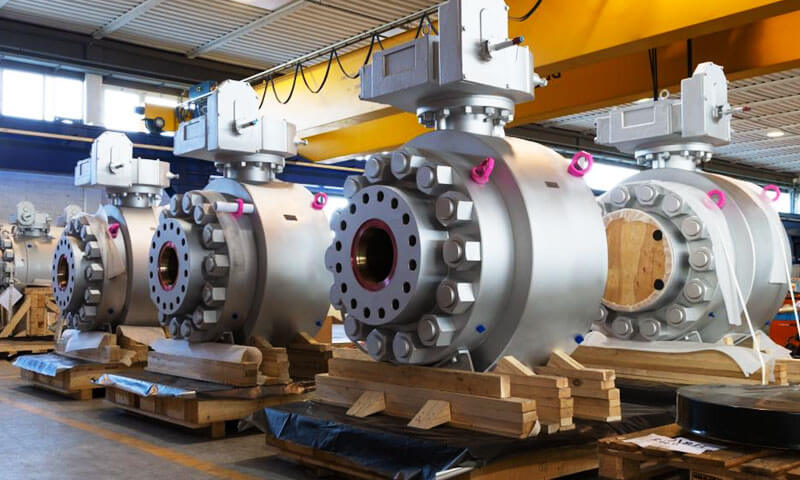
4. Stærðarsamanburðartafla fyrir hliðarventil
Staðlar vísað til: ASME B16.10, ASME B16.5 (Bekk 150), In 558, In 1092-1 (PN16)
Lokategund: Flangað, Hliðarventill með fullri höfn
Gert er ráð fyrir efni: Kolefnisstál (WCB), Rising Stem Design
| NPS (In) | DN (mm) | Raunverulegur Bore (auðkenni, mm) | Augliti til auglitis (mm) | Flans OD (mm) | Boltahringur Ø (mm) | Nei. af Boltum | Bolthol Ø (mm) |
|---|---|---|---|---|---|---|---|
| 2 | 50 | 51 | 178 | 152 | 120.5 | 4 | 19 |
| 2½ | 65 | 64 | 190 | 178 | 139.7 | 4 | 19 |
| 3 | 80 | 76 | 203 | 190 | 152.4 | 4 | 19 |
| 4 | 100 | 102 | 229 | 229 | 190.5 | 8 | 19 |
| 5 | 125 | 127 | 254 | 254 | 216 | 8 | 22 |
| 6 | 150 | 152 | 267 | 279 | 241.3 | 8 | 22 |
| 8 | 200 | 203 | 292 | 343 | 298.5 | 8 | 22 |
| 10 | 250 | 254 | 330 | 406 | 362 | 12 | 25 |
| 12 | 300 | 305 | 356 | 483 | 431.8 | 12 | 25 |
| 14 | 350 | 337 | 381 | 533 | 476.3 | 12 | 29 |
| 16 | 400 | 387 | 406 | 597 | 539.8 | 16 | 29 |
| 18 | 450 | 438 | 432 | 635 | 577.9 | 16 | 32 |
| 20 | 500 | 489 | 457 | 699 | 635 | 20 | 32 |
| 24 | 600 | 591 | 508 | 813 | 749.3 | 20 | 35 |
Athugasemdir:
- Raunverulegur Bore (auðkenni) getur verið örlítið breytilegt eftir framleiðanda og útfærslustíl; gildi eru dæmigerð fyrir hönnun með fullri höfn.
- Augliti til auglitis gildi fylgja ASME B16.10 eða EN 558 Röð 1.
- Flans OD, Boltahringur, Og Boltamál fylgdu ASME B16.5 flokki 150 / In 1092-1 PN16 eftir því sem við á.
- Allar stærðir eru í millimetrar nema annað sé tekið fram.
- Sérsniðin ventilhönnun eða hærri þrýstingsflokkar (Bekk 300, PN25) mun krefjast mismunandi flans og líkamsstærðar.
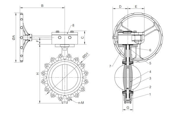
5. Stærðarsamanburðartöflu fiðrildaloka
Lokategund: Soft Seal Butterfly loki í oblátastíl
Staðlar: In 558 Röð 20 (Augliti til auglitis), In 1092-1 (Flans), ASME B16.5 flokkur 150 Flansar
Þrýstingsmat: PN10 / PN16 / ANSI Class 150
| DN (mm) | NPS (In) | Augliti til auglitis (mm) | Ytra þvermál flans (AF, mm) | Þvermál boltahringsins (BCD, mm) | Fjöldi boltahola | Þvermál boltahola (mm) |
|---|---|---|---|---|---|---|
| 50 | 2 | 108 | 165 | 125 | 4 | 18 |
| 65 | 2½ | 114 | 185 | 145 | 4 | 18 |
| 80 | 3 | 127 | 200 | 160 | 8 | 18 |
| 100 | 4 | 140 | 220 | 180 | 8 | 18 |
| 125 | 5 | 152 | 250 | 210 | 8 | 18 |
| 150 | 6 | 165 | 285 | 240 | 8 | 22 |
| 200 | 8 | 191 | 340 | 295 | 8 | 22 |
| 250 | 10 | 216 | 395 | 350 | 12 | 22 |
| 300 | 12 | 241 | 445 | 400 | 12 | 22 |
| 350 | 14 | 267 | 505 | 460 | 16 | 22 |
| 400 | 16 | 292 | 565 | 515 | 16 | 26 |
| 450 | 18 | 318 | 620 | 565 | 20 | 26 |
| 500 | 20 | 343 | 670 | 620 | 20 | 26 |
| 600 | 24 | 394 | 780 | 725 | 20 | 30 |
Viðbótar athugasemdir:
- Augliti til auglitis mál fyrir EN 558 Röð 20 oblátahönnun tryggir samhæfni við flansa sem eru flokkaðir PN10/PN16 eða ANSI Class 150.
- Stærðir flans (AF, boltahringur, boltagöt) í samræmi við EN 1092-1 eða ASME B16.5 til að tryggja rétta uppsetningu á milli rörflansa.
- Stærð og fjöldi boltahola samsvarar flansflokki og stærð til að viðhalda þrýstingsheilleika.
- Fiðrildalokar með mjúkum innsigli nota teygjanlegar fóðringar (EPDM, Nbr, Faston) og eru valin fyrir vatn, HVAC, og léttefnaþjónustu.
6. Flans Tegund Soft Seal Butterfly Valve Stærð samanburðartafla
Lokategund: Fiðrildaventill með mjúkum innsigli með flens
Staðlar: In 558 Röð 20 (Augliti til auglitis), In 1092-1 (Flansar PN10/16), ASME B16.5 flokkur 150 Flansar
Þrýstiflokkur: Pn10 / lim16 / ANSI Class 150
| DN (mm) | NPS (In) | Augliti til auglitis (mm) | Ytra þvermál flans (mm) | Þvermál boltahringsins (mm) | Fjöldi boltahola | Þvermál boltahola (mm) |
|---|---|---|---|---|---|---|
| 50 | 2 | 140 | 165 | 125 | 4 | 18 |
| 65 | 2½ | 152 | 185 | 145 | 4 | 18 |
| 80 | 3 | 165 | 200 | 160 | 8 | 18 |
| 100 | 4 | 178 | 220 | 180 | 8 | 18 |
| 125 | 5 | 191 | 250 | 210 | 8 | 18 |
| 150 | 6 | 203 | 285 | 240 | 8 | 22 |
| 200 | 8 | 229 | 340 | 295 | 8 | 22 |
| 250 | 10 | 254 | 395 | 350 | 12 | 22 |
| 300 | 12 | 279 | 445 | 400 | 12 | 22 |
| 350 | 14 | 305 | 505 | 460 | 16 | 22 |
| 400 | 16 | 330 | 565 | 515 | 16 | 26 |
| 450 | 18 | 356 | 620 | 565 | 20 | 26 |
| 500 | 20 | 381 | 670 | 620 | 20 | 26 |
| 600 | 24 | 432 | 780 | 725 | 20 | 30 |
Athugasemdir:
- Augliti til auglitis stærð samsvarar EN 558 Röð 20 flansaður fiðrildaventill staðall, hentugur fyrir uppsetningu á milli flansa sem eru flokkaðir PN10/PN16 eða ANSI Class 150.
- Flans OD, Þvermál boltahringsins, Bolthola Magn og stærð í samræmi við EN 1092-1 og ASME B16.5 til að tryggja samhæfni við staðlaða rörflansa.
- Mjúk innsigli notar venjulega teygjur eins og EPDM, Nbr, gull Viton, veitir framúrskarandi þéttingu fyrir vatn, lofti, og létt efnafræðileg notkun.
- Flansfiðrildalokar gera auðvelt að fjarlægja/skipta án þess að trufla flansa leiðslunnar.
7. Stærð fiðrildaventils samkvæmt EN staðli
Standard: In 558 (Augliti til auglitis) & In 1092-1 (Flans)
Lokategund: Wafer/Flanged, Mjúk innsigli
Þrýstiflokkur: PN10 / PN16
| DN (mm) | Augliti til auglitis lengd (mm) | Ytra þvermál flans (mm) | Þvermál boltahringsins (mm) | Fjöldi boltahola | Þvermál boltahola (mm) |
|---|---|---|---|---|---|
| 50 | 108 | 165 | 125 | 4 | 18 |
| 65 | 114 | 185 | 145 | 4 | 18 |
| 80 | 127 | 200 | 160 | 8 | 18 |
| 100 | 140 | 220 | 180 | 8 | 18 |
| 125 | 152 | 250 | 210 | 8 | 18 |
| 150 | 165 | 285 | 240 | 8 | 22 |
| 200 | 191 | 340 | 295 | 8 | 22 |
| 250 | 216 | 395 | 350 | 12 | 22 |
| 300 | 241 | 445 | 400 | 12 | 22 |
| 350 | 267 | 505 | 460 | 16 | 22 |
| 400 | 292 | 565 | 515 | 16 | 26 |
| 450 | 318 | 620 | 565 | 20 | 26 |
| 500 | 343 | 670 | 620 | 20 | 26 |
| 600 | 394 | 780 | 725 | 20 | 30 |
Útskýring:
- Augliti til auglitis lengd: Fyrir EN 558 Röð 20, á við um obláta og töfra fiðrildaloka.
- Ytra þvermál flans, Þvermál boltahringsins, Boltholanúmer/stærð: Byggt á EN 1092-1 flansstaðlar fyrir PN10 og PN16 þrýstiflokka.
- Þessar stærðir tryggja samhæfni við samsvarandi rörflansa og auðvelda uppsetningu.
- The boltahola mynstur tryggir réttan vélrænan styrk og þéttingarheilleika.
8. Stærðartafla fyrir kúluventilstærð
ANSI stærðir endurspegla bandaríska staðla; EN mál endurspegla evrópska staðla.
Staðlar vísað til: Byggt á ANSI / ASME staðlar
Staðlar vísað til:
- ASME B16.10 - Augliti til auglitis og frá enda til enda
- ASME B16.5 – Flanstengingar (fyrir þrýstiflokka 150–2500)
- ASME B16.34 - Lokahönnun, efni, og þrýstings-hitastig
| DN (mm) | NPS (In) | Augliti til auglitis (mm) ANSI/ASME B16.10 | Flans OD (mm) ANSI B16.5 flokkur 150 | Þvermál boltahringsins (mm) ANSI B16.5 | Fjöldi bolta | Þvermál boltahola (mm) | Augliti til auglitis (mm) In 558 | Flans OD (mm) In 1092-1 PN16 | Þvermál boltahringsins (mm) In 1092-1 | Fjöldi bolta EN 1092-1 | Þvermál boltahola (mm) In 1092-1 |
|---|---|---|---|---|---|---|---|---|---|---|---|
| 50 | 2 | 152 | 165 | 125 | 4 | 18 | 140 | 185 | 145 | 4 | 18 |
| 65 | 2½ | 165 | 190 | 145 | 4 | 18 | 152 | 200 | 160 | 8 | 18 |
| 80 | 3 | 178 | 215 | 160 | 8 | 18 | 165 | 220 | 180 | 8 | 18 |
| 100 | 4 | 190 | 254 | 180 | 8 | 18 | 178 | 250 | 210 | 8 | 18 |
| 125 | 5 | 216 | 279 | 210 | 8 | 22 | 191 | 285 | 240 | 8 | 18 |
| 150 | 6 | 241 | 324 | 241 | 8 | 22 | 216 | 320 | 295 | 8 | 22 |
| 200 | 8 | 292 | 406 | 362 | 8 | 22 | 267 | 405 | 355 | 8 | 22 |
| 250 | 10 | 330 | 483 | 432 | 12 | 25 | 292 | 460 | 410 | 12 | 22 |
| 300 | 12 | 356 | 559 | 483 | 12 | 25 | 318 | 515 | 460 | 12 | 22 |
| 350 | 14 | 394 | 597 | 539 | 16 | 29 | 343 | 565 | 515 | 16 | 22 |
| 400 | 16 | 432 | 673 | 595 | 16 | 29 | 368 | 620 | 565 | 16 | 26 |
| 450 | 18 | 483 | 698 | 622 | 20 | 32 | 394 | 675 | 615 | 20 | 26 |
| 500 | 20 | 508 | 749 | 673 | 20 | 32 | 419 | 730 | 670 | 20 | 26 |
| 600 | 24 | 584 | 864 | 787 | 20 | 35 | 483 | 840 | 780 | 20 | 30 |
Útskýring:
- Augliti til auglitis: Lengd á milli lokaenda, mikilvægt fyrir píputenningu.
- Ytra þvermál flans (AF) Og Þvermál boltahringsins ákvarða samhæfni flans.
- Fjöldi og stærð bolta fer eftir flansstærð og þrýstingsmati.
- Mismunur gæti þurft millistykki eða sérsniðna flansa í alþjóðlegum verkefnum.
9. Multi-Perspective Analysis
Víddar nákvæmni
Þétt vikmörk (±1% á borun, ±2 mm á augliti til auglitis) draga úr misjöfnun við uppsetningu.
Ennfremur, nákvæm mál tryggja rétta þéttingu þjöppunar, varðveita heilleika innsigli undir þrýstingi allt að 250 bar.
Efnisleg eindrægni
Efnisval - kolefnisstál, ryðfríu stáli, eða sérhæfðar málmblöndur - breytir oft veggþykkt og heildarstærð.
Til dæmis, ryðfríir lokar geta verið með 5% þykkari veggir til að gera ráð fyrir tæringarheimildum, breytir þar með lítillega nafnmáli F2F.
Þrýstingur-hitastig
Lokahlutfall verður að vera í samræmi við flokkun flansa.
Sem dæmi, ANSI 300# loki (hámarks vinnuþrýstingur 74 bar kl 100 ° C.) parar við 300# flansar með stærri boltahringjum (216 mm vs. 184 mm fyrir 150#), nauðsynlegt að hafa sérstakan töfludálk fyrir þrýstiflokk.
Umsókn-sértæk sjónarmið
- Petrochemical vs. vatnsmeðferð vs. HVAC: Árásargjarn miðill í jarðolíuverksmiðjum krefst oft sérstakra málmblöndur og strangari vikmörk; Aftur á móti, HVAC lokar geta fylgt lausari ANSI 150# sérstakur.
- Hreinlætismál (þríklemma) vs. iðnaðar flansar: Þríklemmufestingar nota rasssoðnar eða klemmuendatengingar og víkja venjulega algjörlega frá ANSI/DIN boltamynstri,
ábyrgist sérhæft smáborð.
Kostnaðar- og birgðakeðjuáhrif
Staðlaðar lokar (90% af eftirspurn á markaði) njóta styttri afgreiðslutíma (2-4 vikur) og lægri einingakostnaður.
Samt, sérsniðnar stærðir eða sérstakt efni geta teygt afgreiðslutíma í 12–16 vikur og aukið kostnað um 30–50%.
Þar af leiðandi, sokkar vinsælar stærðir (T.d., NPS 2, 4, 6) dregur úr hættu á niðritíma og lækkar birgðakostnað.
10. Niðurstaða
Nákvæm stærð loka og þýðing á milli staðla gegnir lykilhlutverki við að tryggja áreiðanleika verksmiðjunnar, hámarka frammistöðu, og stjórna kostnaði.
Með því að smíða vel skipulagða samanburðartöflu fyrir lokastærð - fullkomin með nauðsynlegum málum, þrýstiflokkar, og efnisskýringar,
Verkfræðiteymi geta hagrætt hönnunargagnrýni, flýta fyrir innkaupum, og lágmarka uppsetningarvillur.
Að lokum, að fjárfesta tíma í að byggja og viðhalda þessum töflum skilar arði í minni niðurtíma, aukið öryggi, og bætt rekstrarhagkvæmni.
Mismunandi lokaframleiðendur geta haft smávægilegar breytingar miðað við staðlaðar stærðir.
Við val á lokum í reynd, það er nauðsynlegt að huga að sérstökum verkþörfum, færibreytur leiðslukerfis, og vöruforskriftir sem framleiðandi gefur til að tryggja nákvæmt val og rétta uppsetningu.
Þetta er hið fullkomna val fyrir framleiðsluþarfir þínar ef þú þarft hágæða loki hluti.

