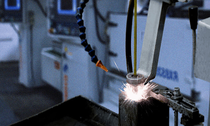

যান্ত্রিক উৎপাদনে, অগণিত উপাদান আকৃতি এবং ফাংশন ভিন্ন চেহারা হতে পারে, কিন্তু তাদের অনেকগুলিকে সীমিত সংখ্যক সাধারণ কাঠামোগত ফর্মগুলিতে শ্রেণীবদ্ধ করা যেতে পারে.
সবচেয়ে প্রতিনিধিদের মধ্যে রয়েছেন শ্যাফ্ট, হাতা, হাউজিংস, গিয়ার্স, পিস্টন, এবং সংযোগকারী রড.
এই অংশগুলিকে মেশিন করার চ্যালেঞ্জটি কেবল একটি কাটার সরঞ্জাম বা মেশিন বেছে নেওয়া নয়.
একটি শব্দ প্রক্রিয়া পরিকল্পনা ফাঁকা নির্বাচন সমন্বয় করতে হবে, তারিখ নকশা, যন্ত্রের ক্রম, ভাতা বিতরণ, তাপ চিকিত্সা, ফিক্সচার ডিজাইন, কাটিং পরামিতি, মাত্রিক পরিদর্শন, এবং উত্পাদনের পরিমাণ.
এই নিবন্ধটি মেশিনিং পদ্ধতিগুলির একটি পদ্ধতিগত ওভারভিউ প্রদান করে, সাধারণ প্রক্রিয়া রুট, মূল প্রযুক্তিগত প্রয়োজনীয়তা, এবং এই ছয়টি প্রতিনিধি যান্ত্রিক অংশের সাথে যুক্ত সাধারণ উত্পাদন চ্যালেঞ্জ.
1. Shaft Parts Machining: The Benchmark of Rotary Component Machining
যান্ত্রিক উত্পাদনের সবচেয়ে প্রতিনিধিত্বকারী উপাদানগুলির মধ্যে খাদ অংশ.
তাদের প্রাথমিক কাজগুলি ঘূর্ণায়মান উপাদানগুলিকে সমর্থন করা, টর্ক প্রেরণ, স্থানান্তর ক্ষমতা, এবং bearings আপেক্ষিক অবস্থান বজায় রাখা, গিয়ার্স, কপিকল, কাপলিংস, এবং অন্যান্য সংক্রমণ উপাদান.
একটি খাদের গুণমান মাত্রিক নির্ভুলতার সমন্বয় দ্বারা নির্ধারিত হয়, ফর্ম নির্ভুলতা, অবস্থানগত নির্ভুলতা, এবং পৃষ্ঠের অখণ্ডতা.
অপেক্ষাকৃত সহজ ছোট shafts জন্য, বৃত্তাকার বার স্টক প্রায়ই লাভজনক কারণ শুরুর জ্যামিতি ইতিমধ্যে চূড়ান্ত নলাকার আকারের আনুমানিক.
উচ্চ শক্তি বা ভারী লোড shafts জন্য, ফরজিং আরও ভাল উপাদান ব্যবহার এবং আরও অনুকূল যান্ত্রিক বৈশিষ্ট্য প্রদান করতে পারে. বড় বা অত্যন্ত জটিল শ্যাফটের জন্য বিশেষ ঢালাই বা ফোরজিং প্রক্রিয়ার প্রয়োজন হতে পারে.

Typical Shaft Machining Process
একটি সাধারণ খাদ মেশিনিং রুট হিসাবে প্রকাশ করা যেতে পারে:
ফাঁকা প্রস্তুতি → মুখোমুখি এবং কেন্দ্র ড্রিলিং → রুক্ষ টার্নিং → হিট ট্রিটমেন্ট → সেমি-ফিনিশিং → সেকেন্ডারি ফিচার মেশিনিং → ফিনিশ টার্নিং → গ্রাইন্ডিং বা সুপারফিনিশিং → চূড়ান্ত পরিদর্শন
খাদ জ্যামিতি এবং উপাদান অনুযায়ী সঠিক ক্রম পরিবর্তিত হয়, কিন্তু ডেটাম স্থায়িত্ব এবং প্রক্রিয়া সিকোয়েন্সিং কেন্দ্রীয় বিবেচনা বজায় রাখা.
অনেক নির্ভুল shafts জন্য, কেন্দ্রের গর্তগুলি প্রাথমিকভাবে প্রতিষ্ঠিত হয় এবং তারপরে পরবর্তী যন্ত্রের জন্য রেফারেন্স ডেটাম হিসাবে ব্যবহৃত হয়.
কেন্দ্রগুলির মধ্যে মেশিনিং একটি সাধারণ অক্ষের সাপেক্ষে বিভিন্ন বাহ্যিক নলাকার পৃষ্ঠ তৈরি করতে দেয়, যা বিশেষত উপকারী যখন সমঅক্ষীয়তা গুরুত্বপূর্ণ.
Why Process Sequencing Matters
শ্যাফ্ট মেশিনিংয়ের একটি প্রধান নীতি হল যথেষ্ট উপাদান অপসারণ করা যখন ওয়ার্কপিসে এখনও পর্যাপ্ত কাঠামোগত অনমনীয়তা থাকে.
উদাহরণস্বরূপ, বড় ব্যাসের মোটামুটি বাঁক সাধারণত ছোট ব্যাসের ব্যাপক মেশিনিংয়ের আগে সঞ্চালিত হয়.
প্রাথমিক পর্যায়ে একটি পাতলা অঞ্চল থেকে খুব বেশি উপাদান সরানো হলে, স্থানীয় দৃঢ়তা হ্রাস পায় এবং খাদ আরও সংবেদনশীল হয়ে ওঠে:
বিচ্যুতি → কম্পন → মাত্রিক ত্রুটি → জ্যামিতিক বিচ্যুতি
তাপ চিকিত্সা প্রক্রিয়া রুট মধ্যে একত্রিত করা আবশ্যক. যখন শক্ত বা টেম্পারিং প্রয়োজন হয়, পরবর্তী অপারেশনের সময় তাপ-চিকিত্সা বিকৃতি দূর করতে পর্যাপ্ত ফিনিশিং ভাতা বজায় রাখা উচিত.
Rough Turning and Semi-Finishing
বেশিরভাগ প্রচলিত শ্যাফ্ট জ্যামিতির জন্য বাঁক প্রাথমিক যন্ত্র প্রক্রিয়া.
রুক্ষ বাঁক প্রধানত দক্ষ উপাদান অপসারণ এবং মৌলিক ধাপযুক্ত প্রোফাইল প্রতিষ্ঠার সাথে সংশ্লিষ্ট.
কাটিং প্যারামিটারগুলি সাধারণত স্থিতিশীল কাটিয়া অবস্থা বজায় রেখে এবং অত্যধিক বিচ্যুতি এড়াতে উত্পাদনশীলতা সর্বাধিক করার জন্য নির্বাচন করা হয়.
সেমি-ফিনিশিং প্রধান কার্যকরী পৃষ্ঠগুলিকে তাদের চূড়ান্ত মাত্রার কাছাকাছি নিয়ে আসে এবং উচ্চ-নির্ভুলতার সমাপ্তির জন্য প্রস্তুত করে.
পাতলা খাদ জন্য, সমর্থন পছন্দ বিশেষ করে গুরুত্বপূর্ণ. Tailstock সমর্থন, স্থির বিশ্রাম, বিশ্রাম অনুসরণ করুন, উপযুক্ত চাকিং পদ্ধতি, এবং অপ্টিমাইজড কাটিয়া পরামিতি উল্লেখযোগ্যভাবে workpiece deflection কমাতে পারে.
উদ্দেশ্য শুধুমাত্র দ্রুত উপাদান অপসারণ করা হয় না, কিন্তু একটি স্থিতিশীল মধ্যবর্তী জ্যামিতি তৈরি করতে যা পরবর্তী নির্ভুলতা ক্রিয়াকলাপগুলিকে নির্ভরযোগ্যভাবে সমর্থন করতে পারে.
Precision Finishing of Shaft Surfaces
যখন shafts উচ্চ মাত্রিক এবং জ্যামিতিক নির্ভুলতা প্রয়োজন, প্রায়শই নাকাল চূড়ান্ত নির্ভুলতা অপারেশন হয়ে ওঠে.
নলাকার নাকাল ব্যাপকভাবে ভারবহন জার্নাল জন্য ব্যবহৃত হয়, স্পষ্টতা shafts, জলবাহী উপাদান, এবং অন্যান্য পৃষ্ঠতলের আঁট সহনশীলতা এবং নিয়ন্ত্রিত পৃষ্ঠ ফিনিস প্রয়োজন.
কেন্দ্রবিহীন নাকাল বড় পরিমাণে তৈরি নলাকার উপাদানগুলির জন্য অত্যন্ত উত্পাদনশীল, বিশেষ করে যখন কেন্দ্রগুলির মধ্যে পৃথক কর্মক্ষেত্র অপ্রয়োজনীয়.
আবেদনের দাবির জন্য, অতিরিক্ত সমাপ্তি কৌশল অন্তর্ভুক্ত হতে পারে:
- সুপারফিনিশিং
- Honing
- পলিশিং
- রোলার জ্বলছে
- ল্যাপিং
এই প্রক্রিয়াগুলি পৃষ্ঠের গঠন উন্নত করতে পারে এবং, পদ্ধতির উপর নির্ভর করে, কাছাকাছি-পৃষ্ঠের বৈশিষ্ট্য যেমন অবশিষ্ট চাপ এবং কঠোরতা পরিবর্তন করুন.
Grinding Is Not Simply About Surface Roughness
একটি সাধারণ ভুল ধারণা হল যে নাকাল শুধুমাত্র একটি মসৃণ পৃষ্ঠ অর্জন করতে ব্যবহৃত হয়. নির্ভুল খাদ উত্পাদন, এর ভূমিকা অনেক বিস্তৃত.
নাকাল সংশোধন করতে পারেন:
- ব্যাস তারতম্য
- টেপার
- গোলাকার ত্রুটি
- নলাকার ত্রুটি
- স্থানীয় পৃষ্ঠের ত্রুটি
তবে, অত্যধিক নাকাল তাপ শক্ত ইস্পাত পৃষ্ঠ স্তর ক্ষতি করতে পারে.
সুতরাং, কুল্যান্ট ডেলিভারি, চাকা নির্বাচন, ড্রেসিং, ফিড, এবং গ্রাইন্ডিং প্যারামিটারগুলি অবশ্যই তাপীয় ক্ষতি বা অবাঞ্ছিত অবশিষ্ট স্ট্রেস রোধ করতে সাবধানে নিয়ন্ত্রণ করতে হবে.
Machining Keyways, স্প্লাইন্স, and Threads
শ্যাফ্টগুলিতে প্রায়শই সেকেন্ডারি কার্যকরী বৈশিষ্ট্য থাকে যা অবশ্যই মূল ঘূর্ণন অক্ষের সাথে সঠিকভাবে সম্পর্কিত থাকতে হবে.
কীওয়ে মিলিং দ্বারা উত্পাদিত হতে পারে, ব্রোচিং, গঠন, বা বিশেষ মেশিনিং পদ্ধতি. তাদের প্রস্থ, গভীরতা, অবস্থান, এবং কৌণিক অভিযোজন টর্ক ট্রান্সমিশন এবং সমাবেশকে প্রভাবিত করে.
স্প্লাইনগুলি আরও জটিল কারণ একাধিক দাঁত অবশ্যই খাদের পরিধির চারপাশে সঠিকভাবে বিতরণ করা উচিত.
স্প্লাইন ডিজাইন এবং উৎপাদন ভলিউমের উপর নির্ভর করে, প্রসেস যেমন ব্রোচিং, গঠন, hobbing, মিলিং, অথবা নাকাল ব্যবহার করা যেতে পারে.
থ্রেড বাঁক দ্বারা machined করা যেতে পারে, থ্রেড মিলিং, অভ্যন্তরীণ বৈশিষ্ট্যগুলির জন্য আলতো চাপুন, বা উচ্চ নির্ভুলতা অ্যাপ্লিকেশনের জন্য নাকাল.
একটি গুরুত্বপূর্ণ প্রক্রিয়া-পরিকল্পনা নীতি হল যে এই গৌণ বৈশিষ্ট্যগুলি নিয়ন্ত্রিত কার্যকরী ডেটাম থেকে মেশিন করা উচিত.
অন্যথায়, শ্যাফ্টের সঠিক পৃথক বৈশিষ্ট্য থাকতে পারে তবে তাদের মধ্যে ভুল কৌণিক বা অবস্থানগত সম্পর্ক থাকতে পারে.
Special Shaft Parts: Crankshafts and Lead Screws
কিছু শ্যাফ্ট উপাদানগুলির জন্য বিশেষ প্রক্রিয়া কৌশল প্রয়োজন কারণ তাদের জ্যামিতি প্রচলিত বাঁক অতিক্রম করে.
ক্র্যাঙ্কশ্যাফ্ট
ক্র্যাঙ্কশ্যাফটে একাধিক অফসেট জার্নাল থাকে, প্রধান জার্নাল এবং ক্র্যাঙ্কপিন সহ.
তাদের যন্ত্রের জন্য জার্নাল ব্যাসের সুনির্দিষ্ট নিয়ন্ত্রণ প্রয়োজন, ক্র্যাঙ্ক নিক্ষেপ, কৌণিক অবস্থান, ফিললেট, তেল প্যাসেজ, এবং গতিশীল ভারসাম্য.
সাধারণ প্রক্রিয়ার মধ্যে বিশেষ বাঁক অন্তর্ভুক্ত থাকতে পারে, গ্রাইন্ডিং, ড্রিলিং, ফিললেট সমাপ্তি, পলিশিং, এবং ভারসাম্য.
কারণ ক্র্যাঙ্কশ্যাফ্টগুলি গুরুতর সাইক্লিক লোডিং অনুভব করে, ফিললেট এবং জার্নাল ট্রানজিশনে পৃষ্ঠের অখণ্ডতা বিশেষভাবে গুরুত্বপূর্ণ.
সীসা স্ক্রু
সীসা স্ক্রুগুলির জন্য থ্রেড প্রোফাইলের কঠোর নিয়ন্ত্রণ প্রয়োজন, পিচ, সীসা নির্ভুলতা, সরলতা, এবং পৃষ্ঠ সমাপ্তি.
নির্ভুল অ্যাপ্লিকেশন, তাপ চিকিত্সার পরে থ্রেড গ্রাইন্ডিং বা অন্যান্য উচ্চ-নির্ভুলতা প্রক্রিয়ার প্রয়োজন হতে পারে.
যেমন উপাদান জন্য, প্রক্রিয়ার উদ্দেশ্য অন্তর্ভুক্ত করার জন্য মাত্রিক নির্ভুলতার বাইরে প্রসারিত পুরো কাজের দৈর্ঘ্যের উপর গতির নির্ভুলতা.
2. Sleeve & Bushing Parts Machining: Bore Precision as the Core Technical Challenge
হাতা এবং বুশিং অংশগুলি সমর্থনকারী হিসাবে ব্যাপকভাবে ব্যবহৃত হয়, পথপ্রদর্শক, পজিশনিং, sealing, এবং যান্ত্রিক সরঞ্জাম পরিধান-প্রতিরোধী উপাদান.
সাধারণ উদাহরণ ভারবহন ঝোপ অন্তর্ভুক্ত, গাইড হাতা, স্পেসার হাতা, খাদ হাতা, জলবাহী বুশিং, সিলিন্ডার লাইনার, এবং হাতা পরিধান.
যদিও তাদের মৌলিক জ্যামিতি প্রায়শই তুলনামূলকভাবে সহজ হয় - একটি বহিরাগত নলাকার পৃষ্ঠের সাথে মিলিত একটি নলাকার অভ্যন্তরীণ গর্ত - যন্ত্রের প্রয়োজনীয়তাগুলি তাদের চেহারার চেয়ে অনেক বেশি দাবি করতে পারে.
হাতা এবং বুশিং মেশিনিংয়ের কেন্দ্রীয় চ্যালেঞ্জটি কেবল একটি সঠিক বোর বা বাইরের ব্যাস তৈরি করা নয়.
গুরুত্বপূর্ণ প্রয়োজন হল বোরের মধ্যে জ্যামিতিক সম্পর্ক বজায় রাখা, বাইরের ব্যাস, শেষ মুখ, এবং কার্যকরী অক্ষ.
অনেক অ্যাপ্লিকেশনে, এমনকি ঘনত্ব বা লম্বতার একটি ছোট ত্রুটি অসম লোডিং হতে পারে, অত্যধিক পরিধান, ফুটো, কম্পন, বা অকাল ব্যর্থতা.

Typical Machining Process for Sleeve Parts
একটি সাধারণ মেশিনিং রুট হিসাবে বর্ণনা করা যেতে পারে:
ফাঁকা প্রস্তুতি → মুখোমুখি → রুক্ষ বাঁক → ড্রিলিং বা রুক্ষ বিরক্তিকর → প্রয়োজনে তাপ চিকিত্সা → সেমি-ফিনিশিং → নির্ভুল বোরিং বা রিমিং → অভ্যন্তরীণ গ্রাইন্ডিং/হোনিং → চূড়ান্ত পরিদর্শন
সঠিক ক্রম হাতা গঠন এবং প্রয়োজনীয় নির্ভুলতার উপর নির্ভর করে.
অপেক্ষাকৃত সহজ এবং কম নির্ভুলতা বুশিংয়ের জন্য, ড্রিলিং এর পর রিমিং পর্যাপ্ত বোরের নির্ভুলতা প্রদান করতে পারে.
যখন কঠোর সহনশীলতা এবং ভাল জ্যামিতিক নিয়ন্ত্রণ প্রয়োজন হয়, বিরক্তিকর, অভ্যন্তরীণ নাকাল, honing, অথবা ল্যাপিং চালু করা যেতে পারে.
একটি ব্যবহারিক অগ্রগতি হয়:
ড্রিলিং → বোরিং → রিমিং → গ্রাইন্ডিং/হোনিং
প্রতিটি প্রক্রিয়া ক্রমবর্ধমান নির্ভুলতার সাথে একই ক্রিয়াকলাপ পুনরাবৃত্তি করার পরিবর্তে একটি ভিন্ন উদ্দেশ্য পরিবেশন করে.
বোর মেশিনিং: From Roughing to Precision Finishing
ড্রিলিং
ড্রিলিং সাধারণত কঠিন ফাঁকা জায়গায় প্রাথমিক গর্ত তৈরি করতে ব্যবহৃত হয়. এটি উচ্চ উত্পাদনশীলতা প্রদান করে কিন্তু সাধারণত একটি নির্ভুল কার্যকরী বোরের জন্য প্রয়োজনীয় জ্যামিতিক নির্ভুলতা প্রদান করে না.
গর্ত অবস্থান, সরলতা, এবং ড্রিল বিচ্যুতি পরবর্তী সমস্ত ক্রিয়াকলাপকে প্রভাবিত করতে পারে, তাই প্রাথমিক গর্ত একটি হিসাবে দেখা উচিত শুরু জ্যামিতি বরং চূড়ান্ত বোর.
বিরক্তিকর
বোরিং একটি বিদ্যমান গর্ত থেকে উপাদান সরিয়ে দেয় এবং ব্যাসের উপর অনেক বেশি নিয়ন্ত্রণ প্রদান করে, সরলতা, গোলতা, এবং অবস্থানগত নির্ভুলতা.
নির্ভুল হাতা জন্য, boring is often the key intermediate operation because it corrects errors introduced during drilling and establishes a reliable geometry for subsequent finishing.
রিমিং
Reaming is used primarily to improve bore size accuracy and surface finish after a suitable pre-machined hole has been produced.
It is efficient for relatively consistent production when the required tolerance is within the capability of the process.
তবে, reaming is not a substitute for correcting a fundamentally inaccurate or misaligned hole. The quality of the result still depends on the previous boring or drilling operation.
অভ্যন্তরীণ নাকাল
Internal grinding is used when high dimensional and geometric accuracy is required, particularly for hardened or precision components.
It can improve:
- বোর ব্যাস
- গোলাকার
- নলাকারতা
- পৃষ্ঠের রুক্ষতা
Grinding allowances must be carefully controlled, বিশেষ করে ছোট-ব্যাস বা পাতলা-প্রাচীরের হাতা জন্য.
Honing
Honing একটি সমাপ্তি প্রক্রিয়া বিশেষ করে নলাকার বোরের জন্য উপযুক্ত.
এটি জ্যামিতিক নির্ভুলতা এবং পৃষ্ঠের টেক্সচার উভয়ই উন্নত করতে পারে এবং সিলিন্ডার লাইনারের জন্য ব্যাপকভাবে ব্যবহৃত হয়, জলবাহী উপাদান, নির্ভুল bushings, এবং ভারবহন পৃষ্ঠতল.
হোনিংয়ের প্রধান সুবিধাগুলির মধ্যে একটি হল একটি নিয়ন্ত্রিত ক্রস-হ্যাচড সারফেস প্যাটার্ন তৈরি করার ক্ষমতা যা উপযুক্ত অ্যাপ্লিকেশনগুলিতে লুব্রিকেন্ট ধারণকে সমর্থন করতে পারে.
Thin-Wall Sleeves: Deformation Is the Main Challenge
পাতলা-প্রাচীরের হাতাগুলি সঠিকভাবে মেশিনের জন্য আরও কঠিন উপাদানগুলির মধ্যে একটি কারণ তাদের দৃঢ়তা সীমিত।.
মেশিনিং সময়, কাটিং ফোর্স অস্থায়ীভাবে ওয়ার্কপিসকে বিকৃত করতে পারে.
ফিক্সচার ছাড়ার পর, ইলাস্টিক বিকৃতি আংশিকভাবে পুনরুদ্ধার করতে পারে, যার ফলে পরিমাপ করা বোর বা বাইরের ব্যাস পরিবর্তন হয়.
এটি একটি সাধারণ পরিস্থিতি তৈরি করে:
ক্ল্যাম্পিং লোডের অধীনে মেশিন করা → মাত্রা সঠিক দেখাচ্ছে → ফিক্সচার থেকে মুক্তি → জ্যামিতি পরিবর্তন
হাতা খুব পাতলা হলে সমস্যা আরও তীব্র হয়, দীর্ঘ, বা তুলনামূলকভাবে নরম উপাদান থেকে তৈরি.
Three Main Methods of Deformation Control
1. কাটা শক্তি হ্রাস করুন
উপযুক্ত কাটিয়া পরামিতি, ধারালো সরঞ্জাম, উপযুক্ত টুল জ্যামিতি, এবং কাটা নিয়ন্ত্রিত গভীরতা রেডিয়াল কাটিয়া শক্তি কমাতে পারে.
2. ক্ল্যাম্পিং অপ্টিমাইজ করুন
ওয়ার্কহোল্ডিং সিস্টেমকে অবশ্যই অতিরিক্ত শক্তি প্রয়োগ না করে উপাদানটিকে নিরাপদে ধরে রাখতে হবে.
নরম চোয়াল, প্রসারিত mandrels, অভ্যন্তরীণ সমর্থন, এবং বিশেষভাবে ডিজাইন করা ফিক্সচারগুলি ক্ল্যাম্পিং লোডগুলিকে আরও সমানভাবে বিতরণ করতে সহায়তা করতে পারে.
3. তাপ নিয়ন্ত্রণ করুন
তাপ কাটার ফলে টুল এবং ওয়ার্কপিস উভয়ই প্রসারিত হতে পারে. তাপমাত্রা স্থিতিশীল না হলে, যন্ত্রের পরপরই নেওয়া মাত্রিক পরিমাপ প্রকৃত কক্ষ-তাপমাত্রার জ্যামিতির প্রতিনিধিত্ব নাও করতে পারে.
নির্ভুল উপাদান জন্য, কুল্যান্ট ডেলিভারি এবং তাপ স্থিতিশীলতা তাই নামমাত্র কাটিয়া পরামিতি হিসাবে গুরুত্বপূর্ণ হতে পারে.
Bore-to-OD Concentricity Is Often More Important Than Individual Size
একটি হাতার সবচেয়ে গুরুত্বপূর্ণ বৈশিষ্ট্যগুলির মধ্যে একটি হল এর বোর এবং বাইরের ব্যাসের মধ্যে সম্পর্ক.
একটি হাউজিং এবং একটি ঘূর্ণায়মান খাদ বহন মধ্যে ইনস্টল একটি bushing বিবেচনা করুন.
এমনকি যদি বোরের ব্যাস এবং বাইরের ব্যাস উভয়ই সহনশীলতার মধ্যে থাকে, তাদের মধ্যে অত্যধিক উদ্ভটতা অসম প্রাচীর বেধ এবং একটি অফসেট চলমান অক্ষ তৈরি করতে পারে.
এই হতে পারে:
- অসম ভারবহন চাপ
- ত্বরিত পরিধান
- বর্ধিত ঘর্ষণ
- খাদ মিসলাইনমেন্ট
- স্থানীয় গরম
- সিলিং কর্মক্ষমতা হ্রাস
এই কারণে, প্রক্রিয়াটি অভ্যন্তরীণ এবং বাহ্যিক রেফারেন্স পৃষ্ঠের মধ্যে একটি স্থিতিশীল সম্পর্ক বজায় রাখতে হবে.
যেখানে উচ্চ ঘনত্ব প্রয়োজন, একটি সাধারণ ডেটাম থেকে উভয় পৃষ্ঠকে মেশিন করা বা একটি নিয়ন্ত্রিত একক-সেটআপ কৌশল ব্যবহার করা জমে থাকা লোকেটিং ত্রুটিগুলি হ্রাস করতে পারে.
Deep-Hole Sleeve Machining
লম্বা হাতা এবং ডিপ-বোর বুশিংগুলি টুল ডিফ্লেকশন সম্পর্কিত অতিরিক্ত চ্যালেঞ্জের পরিচয় দেয়, চিপ উচ্ছেদ, কুল্যান্ট ডেলিভারি, এবং সোজাতা বোর.
গর্ত তার ব্যাস আপেক্ষিক গভীর হয়, মেশিনিং সিস্টেম ক্রমবর্ধমান সংবেদনশীল হয়ে ওঠে:
- টুল ওভারহ্যাং
- কর্তন শক্তি
- কম্পন
- তাপ জমে
- চিপ উচ্ছেদ
- ওয়ার্কপিস এবং টুলের মিসলাইনমেন্ট
তাই বিশেষায়িত গভীর-গর্ত ড্রিলিং এবং বিরক্তিকর কৌশল প্রয়োজন হতে পারে.
নির্ভুল বিরক্তিকর অপারেশন, ভাসমান বা স্ব-সারিবদ্ধ বিরক্তিকর ব্যবস্থা কাটিং সিস্টেমটিকে বিদ্যমান গর্তটিকে আরও সঠিকভাবে অনুসরণ করতে সহায়তা করতে পারে, মেশিন এবং অ্যাপ্লিকেশন উপর নির্ভর করে.
কার্যকরী কুল্যান্ট ডেলিভারিও অপরিহার্য. দুর্বল চিপ উচ্ছেদ চিপগুলিকে পুনরায় কাটার অনুমতি দিতে পারে, বোর স্কোরিং ঘটাচ্ছে, মাত্রিক অস্থিরতা, এবং ত্বরিত টুল পরিধান.
3. Housing & Box Parts Machining: Combined Machining of Hole Systems and Reference Planes
হাউজিং এবং বাক্সের অংশগুলি যান্ত্রিক সরঞ্জামগুলির মৌলিক কাঠামোগত উপাদান.
সাধারণ উদাহরণের মধ্যে রয়েছে মেশিন-টুল হাউজিং, গিয়ারবক্স কেস, ভারবহন হাউজিংস, পাম্প সংস্থা, সংক্রমণ মামলা, ইঞ্জিন ব্লক, এবং টাকু বাক্স.
shafts এবং sleeves থেকে ভিন্ন, যা ঘূর্ণন পৃষ্ঠ দ্বারা আধিপত্য হয়, হাউজিং অংশে সাধারণত বড় রেফারেন্স প্লেনের সংমিশ্রণ থাকে, ছেদকারী বোর সিস্টেম, মাউন্ট পৃষ্ঠতল, থ্রেডেড গর্ত, অভ্যন্তরীণ গহ্বর, এবং বাহ্যিক কাঠামোগত বৈশিষ্ট্য.
তাদের মেশিনিং অসুবিধা তাই একক বৈশিষ্ট্য থেকে আসে না, কিন্তু অসংখ্য কার্যকরী পৃষ্ঠ এবং গর্ত সিস্টেমের মধ্যে স্থানিক সম্পর্ক বজায় রাখা থেকে.
এই বৈশিষ্ট্যগুলির মাত্রিক এবং জ্যামিতিক নির্ভুলতা সরাসরি সমাবেশের গুণমানকে প্রভাবিত করে, খাদ প্রান্তিককরণ, ভারবহন কর্মক্ষমতা, কম্পন, sealing, এবং সম্পূর্ণ মেশিনের অপারেটিং স্থায়িত্ব.

Key Machining Requirements
সবচেয়ে গুরুত্বপূর্ণ প্রয়োজনীয়তা বোর ব্যাস অন্তর্ভুক্ত, গর্ত-অবস্থান নির্ভুলতা, সমক্ষীয়তা, সমতল সমতলতা, লম্ব, সমান্তরালতা, এবং পৃষ্ঠ সমাপ্তি.
বিয়ারিং হাউজিং এবং ট্রান্সমিশনের ক্ষেত্রে, একাধিক বোরের মধ্যে সম্পর্ক বিশেষভাবে গুরুত্বপূর্ণ কারণ যেকোন ভুল বিন্যাস শ্যাফট সারিবদ্ধকরণকে প্রভাবিত করতে পারে, ভারবহন লোডিং, গিয়ার মেশিং, কম্পন, এবং সেবা জীবন.
| প্রয়োজনীয়তা | মূল উদ্দেশ্য |
| নির্ভুলতা | সঠিক ভারবহন এবং খাদ ফিট নিশ্চিত করে |
| গর্ত-অবস্থান নির্ভুলতা | সঠিক সমাবেশ জ্যামিতি বজায় রাখে |
| সমক্ষীয়তা | একাধিক বিয়ারিং বোর সারিবদ্ধ রাখে |
| সমতল সমতলতা | স্থিতিশীল মাউন্ট এবং সমাবেশ প্রদান করে |
| লম্বতা / সমান্তরালতা | সঠিক জ্যামিতিক সম্পর্ক বজায় রাখে |
| সারফেস ফিনিস | ফিটিং সমর্থন করে, sealing, এবং যোগাযোগ কর্মক্ষমতা |
Datum Selection and Process Planning
ডেটাম নির্বাচন হাউজিং মেশিনিং এর ভিত্তি. একটি স্থিতিশীল এবং পুনরাবৃত্তিযোগ্য রেফারেন্স সিস্টেম তৈরি করা উচিত গুরুত্বপূর্ণ বৈশিষ্ট্যগুলি মেশিন করার আগে.
একক-পিস বা ছোট-ব্যাচ উত্পাদনে, রুক্ষ ঢালাই ডিজাইন রেফারেন্স অনুযায়ী ম্যানুয়ালি সারিবদ্ধ করা যেতে পারে.
ব্যাপক উৎপাদনে, ফিক্সচার-ভিত্তিক লোকেটিং সিস্টেম যেমন এক-বিমান-দুই-পিন নীতি দ্রুত এবং আরো পুনরাবৃত্তিযোগ্য অবস্থান প্রদান.
মেশিনিং সিকোয়েন্স সাধারণত "ডেটাম ফার্স্ট" এর নীতি অনুসরণ করে, গর্ত আগে প্লেন, শেষ করার আগে রুক্ষ।"
প্রধান রেফারেন্স পৃষ্ঠতল প্রথম প্রতিষ্ঠিত হয়, সমালোচনামূলক গর্ত সিস্টেম দ্বারা অনুসরণ.
একই স্থানাঙ্ক সিস্টেমের মধ্যে গুরুত্বপূর্ণ ক্রিয়াকলাপগুলি ক্রমবর্ধমান পজিশনিং ত্রুটিগুলি হ্রাস করতে সহায়তা করে.
Machining Reference Planes and Hole Systems
রেফারেন্স প্লেন সাধারণত দ্বারা মেশিন করা হয় মিলিং, পরিকল্পনা, বা নাকাল, উপাদান আকার এবং নির্ভুলতা প্রয়োজনীয়তা উপর নির্ভর করে.
প্রাথমিক ডেটাম পৃষ্ঠতল স্থাপন করা হয় পরে, গর্ত সিস্টেম তুরপুন দ্বারা উত্পাদিত হতে পারে, রিমিং, বিরক্তিকর, বা বিশেষ যন্ত্র.
সাধারণ মাউন্ট গর্ত জন্য, তুরপুন যথেষ্ট হতে পারে. নির্ভুল ভারবহন বোর প্রায়ই বিরক্তিকর বা শেষ অপারেশন প্রয়োজন. যেখানে বেশ কয়েকটি বোর অবশ্যই একটি সাধারণ অক্ষ ভাগ করে নেবে, লাইন বিরক্তিকর চমৎকার সমাক্ষ নিয়ন্ত্রণ প্রদান করতে পারেন.
সমন্বয় মেশিনিং এবং সিএনসি মেশিনিং কেন্দ্রগুলি বিশেষভাবে উপযুক্ত যখন একাধিক গর্তের অবস্থানগুলি সঠিকভাবে নিয়ন্ত্রণ করতে হবে এবং উত্পাদন নমনীয়তা গুরুত্বপূর্ণ.
Typical Machining Route
একটি প্রতিনিধিত্বমূলক প্রক্রিয়া:
ফাঁকা প্রস্তুতি → ডেটাম-প্লেন মেশিনিং → মেজর-প্লেন মেশিনিং → রুক্ষ গর্ত মেশিনিং → সেমি-ফিনিশিং → নির্ভুল বোরিং/মিলিং → থ্রেডিং এবং সেকেন্ডারি বৈশিষ্ট্য → চূড়ান্ত সমাপ্তি এবং পরিদর্শন
রাফিং এবং ফিনিশিং আলাদা করা কাটিং ফোর্সের প্রভাব কমাতে সাহায্য করে, অবশিষ্ট চাপ, এবং চূড়ান্ত নির্ভুলতার উপর তাপীয় বিকৃতি.
বড় কাস্ট হাউজিং জন্য, স্ট্রেস রিলিফ বা স্থিতিশীলতাও সূক্ষ্ম যন্ত্রের আগে প্রয়োজন হতে পারে কারণ প্রচুর পরিমাণে উপাদান অপসারণ করা অবশিষ্ট স্ট্রেস ছেড়ে দিতে পারে এবং মাত্রিক আন্দোলনের কারণ হতে পারে.
Why Hole-System Accuracy Matters
একটি আবাসনে, স্বতন্ত্র মাত্রা শুধুমাত্র মানের প্রয়োজন অংশ.
একটি ভারবহন বোর তার ব্যাস সহনশীলতা পূরণ করতে পারে কিন্তু তারপরও কার্যকরী সমস্যা সৃষ্টি করে যদি এর অক্ষ অন্য বোর বা মাউন্টিং পৃষ্ঠের তুলনায় ভুলভাবে অবস্থান করে।.
সুতরাং, হাউজিং মেশিনিং এর মূল উদ্দেশ্য:
রেফারেন্স প্লেনগুলির মধ্যে সঠিক এবং স্থিতিশীল জ্যামিতিক সম্পর্ক স্থাপন করা, নির্ভুলতা bores, মাউন্ট গর্ত, এবং অন্যান্য কার্যকরী বৈশিষ্ট্য.
নমনীয় উত্পাদন জন্য, সিএনসি মেশিনিং সেন্টারগুলি নির্ভুলতা এবং অভিযোজনযোগ্যতার একটি কার্যকর সমন্বয় অফার করে.
উচ্চ ভলিউম উত্পাদন জন্য, ডেডিকেটেড ফিক্সচার, বিরক্তিকর সিস্টেম, স্বয়ংক্রিয় সরঞ্জাম, এবং ইন-প্রসেস পরিদর্শন উচ্চতর পুনরাবৃত্তিযোগ্যতা এবং উত্পাদনশীলতা প্রদান করতে পারে.
মৌলিক নীতি একই থাকে: প্রথমে ডেটাম সিস্টেম নিয়ন্ত্রণ করুন, তারপর এটির চারপাশে পুরো গর্ত এবং পৃষ্ঠের জ্যামিতি তৈরি করুন.
4. Cylindrical Gears Machining: Tooth Profile Machining as the Process Core
নলাকার গিয়ার্স টর্ক প্রেরণ করতে ব্যবহৃত অপরিহার্য সংক্রমণ উপাদান, ঘূর্ণন গতি পরিবর্তন, এবং shafts মধ্যে একটি সংজ্ঞায়িত গতি সম্পর্ক বজায় রাখা.
সাধারণ উদাহরণের মধ্যে রয়েছে স্পার গিয়ার, হেলিকাল গিয়ারস, অভ্যন্তরীণ গিয়ার, এবং অন্যান্য নলাকার গিয়ার ফর্ম.
তাদের মেশিনিং সাধারণ বাঁক তুলনায় যথেষ্ট বেশি চাহিদা কারণ দাঁত সিস্টেম প্রোফাইলে সঠিক সম্পর্ক বজায় রাখতে হবে, সীসা, পিচ, ব্যবধান, রেডিয়াল রানআউট, এবং গিয়ার বোর বা খাদ অক্ষের সাথে প্রান্তিককরণ.
একটি গিয়ারের গুণমান সরাসরি ট্রান্সমিশন শব্দ প্রভাবিত করে, কম্পন, লোড বিতরণ, দক্ষতা, এবং সেবা জীবন.
সুতরাং, গিয়ার উত্পাদনকে গিয়ার ফাঁকা প্রস্তুতি জড়িত একটি সমন্বিত প্রক্রিয়া হিসাবে বিবেচনা করা উচিত, তারিখ নিয়ন্ত্রণ, দাঁত প্রজন্ম, তাপ চিকিত্সা, সমাপ্তি, এবং চূড়ান্ত পরিদর্শন, শুধু দাঁত কাটার অপারেশন না করে.

Main Machining Requirements for Cylindrical Gears
গিয়ার নির্ভুলতা সাধারণত বিভিন্ন কার্যকরী দৃষ্টিকোণ থেকে মূল্যায়ন করা হয়.
গতির নির্ভুলতা নির্ধারণ করে যে গিয়ারটি উদ্দিষ্ট কৌণিক সম্পর্ককে প্রেরণ করে কিনা, সঠিকতা চালানোর সময় মসৃণতা এবং কম্পন প্রভাবিত করে.
দাঁত-থেকে-দাঁত এবং দাঁত-পৃষ্ঠের নির্ভুলতা কীভাবে জাল করা দাঁত জুড়ে সমানভাবে লোড বিতরণ করা হয় তা প্রভাবিত করে.
| প্রয়োজনীয়তা | ইঞ্জিনিয়ারিং তাৎপর্য |
| দাঁত প্রোফাইল নির্ভুলতা | ডিজাইন করা ইনভোলুট বা পরিবর্তিত দাঁতের জ্যামিতি নিশ্চিত করে |
| সীসা নির্ভুলতা | মুখের প্রস্থ বরাবর দাঁতের সারিবদ্ধতা নিয়ন্ত্রণ করে |
| পিচ নির্ভুলতা | সঠিক দাঁতের ব্যবধান এবং সংক্রমণ অনুপাত বজায় রাখে |
| রেডিয়াল রানআউট | ঘূর্ণনগত সামঞ্জস্য এবং গিয়ার জাল প্রভাবিত করে |
| নির্ভুলতা | খাদের সঠিক অবস্থান নিশ্চিত করে |
| বোর থেকে দাঁতের ঘনত্ব | গিয়ার অক্ষ এবং দাঁত সিস্টেমের মধ্যে সঠিক সম্পর্ক বজায় রাখে |
| দাঁতের পৃষ্ঠের রুক্ষতা | ঘর্ষণকে প্রভাবিত করে, গোলমাল, পরা, এবং ক্লান্তি |
| কঠোরতা এবং কেস গভীরতা | তাপ চিকিত্সার পরে পরিধান প্রতিরোধের এবং লোড বহন করার ক্ষমতা নির্ধারণ করুন |
Typical Cylindrical Gear Machining Process
একটি প্রতিনিধি গিয়ার উত্পাদন রুট হয়:
খালি উত্পাদন → প্রয়োজনে ফাঁকা তাপ চিকিত্সা → গিয়ার ফাঁকা বাঁক → বোর এবং ফেস মেশিনিং → গিয়ার কাটা → তাপ চিকিত্সা → ডেটাম পুনরুদ্ধার → গিয়ার ফিনিশিং → পরিদর্শন
সঠিক ক্রম উপাদান উপর নির্ভর করে, গিয়ার আকার, নির্ভুলতা গ্রেড, তাপ চিকিত্সা পদ্ধতি, এবং উত্পাদনের পরিমাণ.
একটি বিশেষ গুরুত্বপূর্ণ নীতি হল তাপ চিকিত্সার পরে সঞ্চালিত অপারেশনগুলির জন্য পর্যাপ্ত মেশিনিং ভাতা সংরক্ষণ করা.
কার্বারাইজিং এর মতো প্রক্রিয়া, শোধন, এবং টেম্পারিং মাত্রিক এবং জ্যামিতিক পরিবর্তন ঘটাতে পারে.
যদি চূড়ান্ত নির্ভুলতা প্রয়োজন টাইট হয়, এই পরিবর্তনগুলি পূর্ববর্তী মেশিনিং পর্যায়ে অনুমান করা আবশ্যক.
Datum Selection Is Critical
দাঁত সিস্টেম, বোর, এবং শেষ মুখগুলি অবশ্যই একটি সুনির্দিষ্ট স্থানিক সম্পর্ক বজায় রাখতে হবে. সুতরাং, ডেটাম নির্বাচন গিয়ার প্রক্রিয়া পরিকল্পনার সবচেয়ে গুরুত্বপূর্ণ সিদ্ধান্তগুলির মধ্যে একটি.
জন্য খাদ-অখণ্ড গিয়ার, ঘূর্ণন অক্ষ সাধারণত কেন্দ্র গর্ত বা অন্যান্য নিয়ন্ত্রিত খাদ রেফারেন্স মাধ্যমে প্রতিষ্ঠিত হয়. জন্য বোর-টাইপ গিয়ার, বোর এবং শেষ মুখ প্রায়ই কার্যকরী লোকেটিং রেফারেন্স হিসাবে ব্যবহৃত হয়.
নীতি সহজ:
মেশিনিং ডেটামটি গিয়ারের কার্যকরী ঘূর্ণনশীল ডেটামের সাথে ঘনিষ্ঠভাবে সারিবদ্ধ হওয়া উচিত.
খারাপ ডেটাম নির্বাচন এমন একটি গিয়ার তৈরি করতে পারে যাতে দাঁতের প্রোফাইলটি পৃথকভাবে সঠিক তবে পুরো দাঁতের সিস্টেমটি বোরের তুলনায় উদ্ভট।.
এর ফলে অসম মেশিং হতে পারে, বর্ধিত শব্দ, স্থানীয় দাঁত লোডিং, এবং অকাল পরিধান.
Main Tooth-Machining Methods
গিয়ার জ্যামিতি অনুযায়ী বিভিন্ন গিয়ার-কাটিং প্রক্রিয়া নির্বাচন করা হয়, নির্ভুলতা, উত্পাদন ভলিউম, এবং গিয়ারটি অভ্যন্তরীণ বা বাহ্যিক কিনা.
Gear Hobbing
বহিরাগত নলাকার গিয়ার মেশিন করার জন্য হবিং একটি বহুল ব্যবহৃত পদ্ধতি।. একটি ঘূর্ণায়মান হব অবিচ্ছিন্নভাবে দাঁতের জায়গা তৈরি করতে গিয়ার ফাঁকা দিয়ে জড়িত থাকে.
এর প্রধান সুবিধা হল উচ্চ উত্পাদনশীলতা, ক্রমাগত কাটা, এবং স্পার এবং হেলিকাল গিয়ার উভয়ের জন্য উপযুক্ততা. তাই এটি মাঝারি জন্য বিশেষভাবে আকর্ষণীয়- এবং উচ্চ ভলিউম উত্পাদন.
Gear Shaping
গিয়ার শেপিং একটি রেসিপ্রোকেটিং কাটার ব্যবহার করে যা একটি গিয়ারের মতো জেনারেটিং সম্পর্কের মধ্যে ওয়ার্কপিসের সাথে মেশ করে.
কাঁধের কাছাকাছি এবং অভ্যন্তরীণ জ্যামিতির মধ্যে কাজ করার ক্ষমতা এটিকে অভ্যন্তরীণ গিয়ার এবং নির্দিষ্ট গিয়ার কাঠামোর জন্য মূল্যবান করে তোলে যা আটকানো কঠিন।.
Gear Shaving
গিয়ার শেভিং সাধারণত দাঁতের সঠিকতা এবং পৃষ্ঠের অবস্থা উন্নত করতে চূড়ান্ত শক্ত হওয়ার আগে ব্যবহার করা হয়.
এটি পূর্ববর্তী কাটিং অপারেশনের সময় উত্পাদিত ছোট বিচ্যুতিগুলিকে দূর করতে পারে এবং বিশেষত উচ্চ-ভলিউম স্বয়ংচালিত গিয়ার উত্পাদনের সাথে যুক্ত.
Gear Grinding
কঠোর উচ্চ নির্ভুলতা গিয়ার জন্য, নাকাল প্রায়ই চূড়ান্ত দাঁত-সমাপ্ত অপারেশন হয়. এটি দাঁতের প্রোফাইলকে উল্লেখযোগ্যভাবে উন্নত করতে পারে, সীসা, রানআউট, এবং পৃষ্ঠ সমাপ্তি.
গিয়ার গ্রাইন্ডিং এমন অ্যাপ্লিকেশনগুলির জন্য বিশেষভাবে গুরুত্বপূর্ণ যেখানে কম ট্রান্সমিশন শব্দ, উচ্চ লোড ক্ষমতা, এবং সুনির্দিষ্ট গতি সংক্রমণ প্রয়োজন.
Heat Treatment and Post-Heat-Treatment Finishing
তাপ চিকিত্সা প্রায়শই গিয়ার উত্পাদনের সবচেয়ে প্রভাবশালী পর্যায়গুলির মধ্যে একটি কারণ গিয়ারটিকে একই সাথে পৃষ্ঠের কঠোরতা অর্জন করতে হবে, প্রতিরোধ পরুন, ক্লান্তি শক্তি, এবং মাত্রিক স্থায়িত্ব.
গিয়ার উপাদান এবং প্রয়োগের উপর নির্ভর করে, চিকিত্সা অন্তর্ভুক্ত হতে পারে:
- কার্বুরাইজিং
- কার্বনিট্রাইডিং
- নাইট্রাইডিং
- ইন্ডাকশন শক্ত করা
- শক্ত করার মাধ্যমে
কেস-কঠিন গিয়ারের জন্য, একটি শক্ত পরিধান-প্রতিরোধী পৃষ্ঠ এবং একটি শক্ত কোরের সংমিশ্রণ যোগাযোগের ক্লান্তি প্রতিরোধের এবং সামগ্রিক কাঠামোগত শক্তির মধ্যে একটি ভারসাম্য প্রদান করে.
তবে, তাপ চিকিত্সা বিকৃতিও প্রবর্তন করতে পারে, অবশিষ্ট চাপ, এবং মাত্রিক পরিবর্তন. এই কারণেই উচ্চ-নির্ভুল গিয়ারগুলিকে প্রায়শই তাপ চিকিত্সার পরে চূড়ান্ত গ্রাইন্ডিং বা হোনিং অপারেশনের প্রয়োজন হয়.
5. Pistons Machining: Precision Forming for High-Temperature Operating Environments
পিস্টন হল অভ্যন্তরীণ দহন ইঞ্জিনে গুরুত্বপূর্ণ আদান-প্রদানকারী উপাদান, সংকোচকারী, এবং অন্যান্য পাওয়ার সিস্টেম.
তারা উচ্চ তাপমাত্রার অধীনে কাজ করে, উচ্চ চাপ, বিকল্প যান্ত্রিক লোড, এবং ক্রমাগত স্লাইডিং যোগাযোগ, তাই তাদের যন্ত্রের প্রয়োজনীয়তা তাপ সম্প্রসারণের সাথে ঘনিষ্ঠভাবে যুক্ত, তৈলাক্তকরণ, sealing, এবং ক্লান্তি কর্মক্ষমতা.
ইঞ্জিন পিস্টনগুলি সাধারণত অ্যালুমিনিয়াম থেকে তৈরি করা হয় কারণ তাদের কম ঘনত্ব এবং অনুকূল তাপ পরিবাহিতা, যদিও বিশেষায়িত অ্যাপ্লিকেশন অন্যান্য উপকরণ ব্যবহার করতে পারে.
একটি প্রচলিত নলাকার উপাদান থেকে ভিন্ন, একটি পিস্টন খুব কমই একটি সরল সোজা সিলিন্ডার হিসাবে মেশিন করা হয়.
এর স্কার্ট, মুকুট, রিং grooves, পিন bores, এবং অভ্যন্তরীণ গহ্বরের বিভিন্ন কার্যকরী প্রয়োজনীয়তা রয়েছে.
কেন্দ্রীয় চ্যালেঞ্জ হল পরিকল্পিত জ্যামিতিকে যথেষ্ট সঠিকভাবে পুনরুত্পাদন করা যাতে পিস্টন প্রকৃত অপারেটিং তাপমাত্রার অধীনে প্রয়োজনীয় চলমান ছাড়পত্র এবং লোড বিতরণ অর্জন করে।, রুম-তাপমাত্রার মাত্রাকে শুধুমাত্র সন্তুষ্ট করার পরিবর্তে.

Main Machining Requirements for Pistons
| প্রয়োজনীয়তা | ইঞ্জিনিয়ারিং তাৎপর্য |
| স্কার্টের ব্যাস এবং প্রোফাইল | পিস্টন এবং সিলিন্ডারের মধ্যে চলমান ক্লিয়ারেন্স নিয়ন্ত্রণ করে |
| স্কার্টের গোলাকারতা | অভিন্ন যোগাযোগ প্রচার করে এবং স্থানীয় লোডিং হ্রাস করে |
| পিন-বোরের নির্ভুলতা | সঠিক পিস্টন-পিন ফিট এবং লোড স্থানান্তর নিশ্চিত করে |
| পিন-বোরের অবস্থান | পিস্টন এবং সংযোগকারী রডের মধ্যে জ্যামিতিক সম্পর্ক বজায় রাখে |
| রিং-খাঁজের মাত্রা | পিস্টন-রিং সিটিং এবং সিলিং নিয়ন্ত্রণ করে |
| খাঁজ অবস্থান এবং সমান্তরালতা | অসম রিং লোডিং এবং সিলিং সমস্যা প্রতিরোধ করে |
| মুকুট জ্যামিতি | দহনকে প্রভাবিত করে, তাপ লোডিং, এবং উপাদান বিতরণ |
| পৃষ্ঠের রুক্ষতা | ঘর্ষণ প্রভাবিত করে, তৈলাক্তকরণ, এবং পরিধান |
পিস্টন স্কার্টটি বিশেষভাবে গুরুত্বপূর্ণ কারণ এর অপারেটিং জ্যামিতি তাপীয় প্রসারণ এবং যান্ত্রিক বিকৃতি দ্বারা প্রভাবিত হয়.
একটি প্রোফাইল যা ঘরের তাপমাত্রায় সামান্য নলাকার নয় তা ইচ্ছাকৃত হতে পারে, পিস্টন গরম করার পরে পছন্দসই চলমান আকারের কাছে যেতে দেয়.
Typical Piston Machining Process
একটি প্রতিনিধি মেশিনিং রুট হয়:
Casting or forging → rough turning → internal machining → pin-bore machining → ring-groove machining → skirt profiling → finishing → inspection
The exact sequence depends on piston design, উপাদান, উত্পাদন ভলিউম, and the relationship between the piston features.
Rough machining is primarily used to establish basic geometry and remove excess material, while finishing operations are responsible for reproducing the functional profile and tight geometric tolerances.
উচ্চ ভলিউম উত্পাদন জন্য, dedicated CNC equipment and automated gauging are often used to maintain consistent dimensions from part to part.
Piston Skirt Profile Machining
One of the most technically demanding operations is machining the skirt profile.
The skirt may incorporate carefully controlled:
- Barrel profiles
- Cam profiles
- Tapers
- Local relief
- Thrust-side geometry
এই বৈশিষ্ট্যগুলি অপারেশন চলাকালীন পিস্টনের বিভিন্ন অঞ্চল দ্বারা অভিজ্ঞ বিভিন্ন তাপীয় সম্প্রসারণ এবং যান্ত্রিক লোডিংয়ের জন্য ক্ষতিপূরণ দেয়.
সুতরাং, পিস্টন মেশিনিং শুধুমাত্র একটি নামমাত্র ব্যাস উত্পাদন একটি বিষয় নয়. প্রক্রিয়া একটি পুনরুত্পাদন আবশ্যক কার্যকরী ত্রিমাত্রিক প্রোফাইল.
আধুনিক সিএনসি সিস্টেমগুলি প্রয়োজনীয় জ্যামিতি অর্জনের জন্য সমন্বয়-নিয়ন্ত্রিত প্রোফাইলিং এবং টুল ক্ষতিপূরণ ব্যবহার করতে পারে, যখন নির্ভুলতা পরিমাপ সিস্টেম ডিজাইন মডেলের বিরুদ্ধে প্রকৃত প্রোফাইল যাচাই করে.
Precision Machining of the Pin Bore
পিস্টন পিন বোর আরেকটি গুরুত্বপূর্ণ বৈশিষ্ট্য কারণ এটি পিস্টন এবং সংযোগকারী রডের মধ্যে লোড স্থানান্তর করে.
এর গুণমান নির্ভর করে:
ব্যাস + গোলতা + নলাকারতা + অবস্থান + প্রান্তিককরণ
একটি ভুল পিন-বোরের অবস্থান পিস্টন গতিকে প্রভাবিত করতে পারে এবং সংযোগকারী-রড এবং ক্র্যাঙ্কশ্যাফ্ট সিস্টেমে অতিরিক্ত লোডিং প্রবর্তন করতে পারে.
পিস্টন ডিজাইনের উপর নির্ভর করে, বোরকে সূক্ষ্ম বোরিং দ্বারা মেশিন করা যেতে পারে এবং তারপরে হোনিং বা অন্য একটি সূক্ষ্ম-সমাপ্তকরণ অপারেশন.
Ring-Groove Machining
রিং grooves সঠিক প্রস্থ বজায় রাখা আবশ্যক, গভীরতা, অবস্থান, এবং সমান্তরালতা যাতে পিস্টনের রিংগুলি সরানো যায় এবং সঠিকভাবে সিল করতে পারে.
দরিদ্র খাঁজ জ্যামিতি হতে পারে:
- অপর্যাপ্ত সিলিং
- অত্যধিক তেল খরচ
- রিং স্টিকিং
- বৃদ্ধি ঘা দ্বারা
- ত্বরিত পরিধান
তাই খাঁজ-ফিনিশিং প্রক্রিয়ার জন্য টুল জ্যামিতি এবং মাত্রিক ক্ষতিপূরণের কঠোর নিয়ন্ত্রণ প্রয়োজন, বিশেষ করে যখন উচ্চ উৎপাদন ভলিউম এ অ্যালুমিনিয়াম খাদ মেশিন.
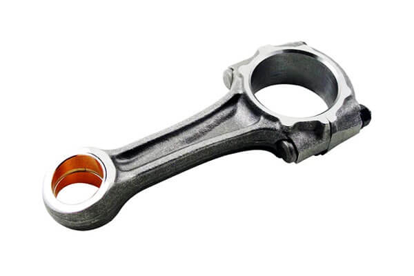
6. Connecting Rods Machining: Deformation Control for Low-Rigidity Components
সংযোগকারী রডগুলি পিস্টনকে ক্র্যাঙ্কশ্যাফ্টের সাথে সংযুক্ত করে এবং পারস্পরিক গতির সময় উত্পন্ন বিকল্প শক্তিকে প্রেরণ করে.
তাদের অবশ্যই উচ্চ চক্রীয় লোড সহ্য করতে হবে, প্রভাব, নমন, এবং ক্লান্তি, অপরিবর্তনীয় ভর কমাতে যথেষ্ট লাইটওয়েট থাকাকালীন.
অধিকাংশ প্রচলিত সংযোগ রড থেকে উত্পাদিত হয় নকল ইস্পাত, যদিও অ্যালুমিনিয়াম এবং অন্যান্য বিশেষ খাদ নির্দিষ্ট অ্যাপ্লিকেশনগুলিতে ব্যবহৃত হয়.
একটি যন্ত্রের দৃষ্টিকোণ থেকে, সংযোগকারী রডগুলি চ্যালেঞ্জিং কারণ তাদের দীর্ঘায়িত গঠন এবং বিভিন্ন ক্রস-সেকশন তাদের তুলনামূলকভাবে কম স্থানীয় অনমনীয়তা দেয়.
ফলস্বরূপ, ক্ল্যাম্পিং বল, কর্তন শক্তি, এবং অবশিষ্ট চাপ সব বিকৃতি হতে পারে, সঠিক বোর জ্যামিতি এবং কেন্দ্রের দূরত্ব বজায় রাখা কঠিন করে তোলে.
Typical Connecting-Rod Machining Process
একটি সাধারণ প্রক্রিয়া রুট হতে পারে:
ফোরজিং → হিট ট্রিটমেন্ট → ডাটাম মেশিনিং → রুক্ষ এক্সটার্নাল মেশিনিং → বোর মেশিনিং → ক্যাপ সেপারেশন → সেমি-ফিনিশিং → প্রিসিশন বোরিং/হোনিং → চূড়ান্ত পরিদর্শন
কানেক্টিং-রড ডিজাইন এবং প্রচলিত মেশিনিং বা ফ্র্যাকচার-বিভক্ত প্রযুক্তি ব্যবহার করা হয় কিনা সে অনুযায়ী ক্রম পরিবর্তিত হয়.
রুক্ষ মেশিনিং স্থিতিশীল রেফারেন্স পৃষ্ঠ স্থাপন করে এবং মেশিনিং ভাতা অধিকাংশ অপসারণ.
নির্ভুল বোরিং এবং হোনিং তারপর চূড়ান্ত বোরের মাত্রা এবং জ্যামিতিক নির্ভুলতা অর্জন করতে ব্যবহৃত হয়.
Bore Machining and Finishing
বড়-এন্ড এবং ছোট-এন্ড বোরগুলি সাধারণত রুক্ষ বোরিংয়ের ক্রম অনুসারে মেশিন করা হয়, সেমি-ফিনিশিং, এবং নির্ভুলতা সমাপ্তি.
বিরক্তিকর সঠিক আকার এবং জ্যামিতিক ফর্ম স্থাপন করে, যখন honing আরও গোলাকার উন্নতি করতে পারে, নলাকারতা, এবং পৃষ্ঠ বৈশিষ্ট্য যেখানে প্রয়োজন.
বড় শেষ সমাবেশের জন্য, রড এবং ক্যাপ মধ্যে সম্পর্ক বিশেষ করে গুরুত্বপূর্ণ.
ক্যাপটি আলাদা এবং পুনরায় একত্রিত করার পরে, সমাপ্ত বোর অবশ্যই ডিজাইন করা জ্যামিতি এবং প্রান্তিককরণ বজায় রাখতে হবে.
Fracture-Split Connecting Rods
ফ্র্যাকচার-বিভাজন উপযুক্ত উচ্চ-ভলিউম সংযোগ-রড ডিজাইনের জন্য ব্যাপকভাবে ব্যবহৃত হয়.
পরিবর্তে রড এবং ক্যাপ মধ্যে একটি প্রচলিত machined মিলন পৃষ্ঠ উত্পাদন, a controlled fracture is initiated along a predetermined region.
The resulting irregular fracture faces provide a highly individual mating interface, helping the cap and rod return to their original relative position during assembly.
This approach can offer:
- Accurate cap-to-rod location
- Reduced relative movement
- Elimination of some conventional machining operations
- Efficient high-volume production
- Consistent assembly positioning when properly controlled
তবে, fracture splitting requires carefully controlled material properties, notch geometry, fracture behavior, এবং প্রক্রিয়া পরামিতি. It is not suitable for every connecting-rod material or design.
The Core Principle of Connecting-Rod Machining
The fundamental challenge is to maintain the accurate spatial relationship between the big-end and small-end bores while preventing deformation of the relatively slender component.
This makes connecting-rod machining a classic example of low-rigidity precision manufacturing. Machine accuracy alone cannot guarantee the final result.
The process must simultaneously control datum selection, fixture loading, কর্তন শক্তি, material removal, তাপ চিকিত্সা, bore finishing, এবং পরিদর্শন.
In high-volume automotive production, the most effective process therefore combines rigid and repeatable fixturing with controlled machining parameters, automated measurement, এবং, যেখানে উপযুক্ত, fracture-split technology.
7. ছয়টি সাধারণ যন্ত্রাংশের তুলনা
Although shafts, হাতা, হাউজিংস, গিয়ার্স, পিস্টন, and connecting rods have very different geometries, their process-planning logic can be compared systematically.
| Part Type | Primary Machining Challenge | Critical Features | Common Processes | Major Control Point |
| খাদ | Rotational accuracy and concentricity | Journals, কাঁধ, থ্রেড, কীওয়ে | বাঁক, গ্রাইন্ডিং, spline machining | Coaxiality and runout |
| Sleeve | Bore accuracy and deformation | বোর, অফ, end face | ড্রিলিং, বিরক্তিকর, রিমিং, honing | Bore-to-OD relationship |
| Housing | Datum and hole-system accuracy | মাউন্ট মুখ, bores, গর্ত | মিলিং, বিরক্তিকর, ড্রিলিং, গ্রাইন্ডিং | Position and geometric accuracy |
| গিয়ার | দাঁতের জ্যামিতি এবং তাপ-চিকিত্সা বিকৃতি | দাঁত প্রোফাইল, সীসা, পিচ, বোর | হবিং, গঠন, শেভিং, honing, গ্রাইন্ডিং | গিয়ার নির্ভুলতা এবং রানআউট |
| পিস্টন | কার্যকরী প্রোফাইল এবং তাপীয় জ্যামিতি | স্কার্ট, পিন বোর, রিং grooves | বাঁক, বিরক্তিকর, খাঁজ যন্ত্র | প্রোফাইল এবং অবস্থানগত নির্ভুলতা |
| সংযোগকারী রড | কম অনমনীয়তা এবং বিকৃতি | ছোট-এন্ড/বিগ-এন্ড বোরস | মিলিং, বিরক্তিকর, honing, ফ্র্যাকচার বিভাজন | বোর প্রান্তিককরণ এবং কেন্দ্রের দূরত্ব |
টেবিল একটি গুরুত্বপূর্ণ প্যাটার্ন দেখায়: মেশিন পদ্ধতি অংশের কার্যকরী জ্যামিতি অনুসরণ করা উচিত.
কোন সর্বজনীনভাবে উচ্চতর যন্ত্র প্রক্রিয়া নেই.
বাঁক ঘূর্ণন পৃষ্ঠতলের জন্য আদর্শ, নির্ভুল অভ্যন্তরীণ ব্যাসের জন্য বিরক্তিকর অপরিহার্য, মিলিং জটিল প্রিজম্যাটিক পৃষ্ঠের উপর আধিপত্য বিস্তার করে, নাকাল তাপ চিকিত্সার পরে উচ্চ নির্ভুলতা প্রদান করে, এবং গঠন বা ফ্র্যাকচার-ভিত্তিক প্রক্রিয়াগুলি উপযুক্ত উচ্চ-ভলিউম উপাদানগুলির জন্য মেশিনের প্রয়োজনীয়তা হ্রাস করতে পারে.
8. উপসংহার
ছয়টি প্রতিনিধি অংশের ধরন-শ্যাফ্ট, হাতা, হাউজিংস, গিয়ার্স, পিস্টন, এবং সংযোগকারী রডযান্ত্রিক যন্ত্র অনুশীলনের একটি দরকারী ক্রস-সেকশন প্রদান করুন.
পার্থক্য থাকা সত্ত্বেও, একই মৌলিক নীতিগুলি বারবার প্রদর্শিত হয়:
সঠিক ডেটাম নির্বাচন → যৌক্তিক প্রক্রিয়া সিকোয়েন্সিং → উপযুক্ত মেশিনিং পদ্ধতি → কার্যকরী বিকৃতি নিয়ন্ত্রণ → নির্ভরযোগ্য পরিদর্শন
এটি মেশিনিং প্রক্রিয়া নকশার আসল ভিত্তি.
উদ্দেশ্য যত তাড়াতাড়ি সম্ভব উপাদান অপসারণ করা হয় না.
একটি সফল যন্ত্র প্রক্রিয়াকে অবশ্যই ফাঁকাকে একটি উপাদানে রূপান্তর করতে হবে যা তার মাত্রিক পূরণ করে, জ্যামিতিক, কার্যকরী, ধাতুবিদ্যা সংক্রান্ত, পৃষ্ঠ, এবং অর্থনৈতিক প্রয়োজনীয়তা ধারাবাহিকভাবে.
ইঞ্জিনিয়ারদের জন্য, প্রক্রিয়া পরিকল্পনাকারী, এবং নির্মাতারা, এই ছয়টি সাধারণ অংশের বিভাগ বোঝা মেশিনিং পদ্ধতির তালিকার চেয়ে বেশি প্রদান করে.
এটি অপরিচিত উপাদান বিশ্লেষণ এবং অংশ কাঠামোর উপর ভিত্তি করে একটি প্রক্রিয়া রুট নির্বাচন করার জন্য একটি ব্যবহারিক কাঠামো অফার করে, কার্যকরী প্রয়োজনীয়তা, বস্তুগত আচরণ, নির্ভুলতা, এবং উত্পাদনের পরিমাণ.
FAQS
এই ছয় প্রকারের মধ্যে মেশিনের কাছে সবচেয়ে চ্যালেঞ্জিং অংশ কি?
এটা নির্ভুলতা গ্রেড উপর নির্ভর করে, কিন্তু সাধারণত গিয়ার এবং পিস্টন সর্বোচ্চ প্রক্রিয়া জটিলতা উপস্থাপন করে.
গিয়ারের জন্য বিশেষ দাঁতের প্রোফাইল মেশিনিং এবং আঁটসাঁট জ্যামিতিক সহনশীলতা প্রয়োজন, যখন পিস্টনগুলির জটিল বাঁকা প্রোফাইল এবং একাধিক ডেটাম স্থানান্তরের সুনির্দিষ্ট নিয়ন্ত্রণ প্রয়োজন.
কোন প্রক্রিয়া সর্বোচ্চ নির্ভুলতা গিয়ার দাঁত গুণমান প্রদান করে?
গিয়ার গ্রাইন্ডিং সর্বোচ্চ দাঁত প্রোফাইল নির্ভুলতা তৈরি করে এবং স্পষ্টতা গ্রেড শক্ত গিয়ারের জন্য আদর্শ প্রক্রিয়া.
এটি তাপ চিকিত্সা থেকে বিকৃতি সংশোধন করতে পারে এবং সর্বোচ্চ AGMA বা DIN নির্ভুলতা গ্রেড অর্জন করতে পারে.
হাউজিং মেশিনিংয়ে কেন ডেটাম নির্বাচন এত গুরুত্বপূর্ণ?
হাউজিংগুলির একাধিক আন্তঃসম্পর্কিত গর্ত ব্যবস্থা এবং মিলনের মুখ রয়েছে. সমস্ত অবস্থানগত সহনশীলতা প্রাথমিক তথ্য থেকে স্ট্যাক আপ.
খারাপ ডেটাম নির্বাচন ক্রমবর্ধমান প্রান্তিককরণ ত্রুটি তৈরি করে যা সরাসরি সমাবেশ ফিট এবং মেশিনের কার্যকারিতা হ্রাস করে.
সংযোগকারী রডগুলির জন্য ফ্র্যাকচার বিভাজনের সুবিধা কী??
ফ্র্যাকচার বিভাজন একটি পুরোপুরি মিলে যাওয়া তৈরি করে, রড এবং ক্যাপের মধ্যে ফর্ম-লকিং ইন্টারফেস.
This improves assembly accuracy, eliminates machining of the mating surface, reduces parts count, and increases big-end structural integrity.
ভারবহন হাতা bores জন্য মান ফিনিস কি?
Most precision bearing bores are finished by honing, which produces excellent roundness, controlled surface texture, and consistent size.
For very high precision applications, bore grinding or superfinishing may be specified.