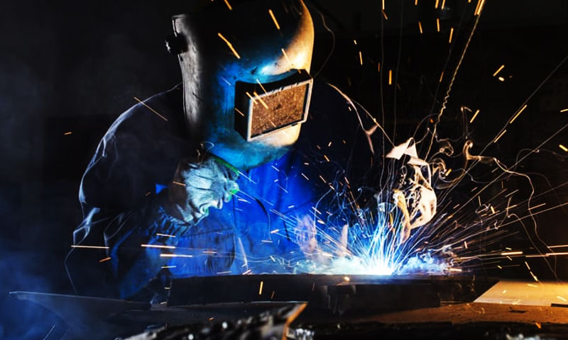
1. giriiş
“Sac metal” genellikle kabaca metal stoğunu ifade eder. 0.2 mm ila 6 mm kalınlık (endüstri tanımları farklılık gösteriyor).
Bu ölçekte kaynak yapmak bir dengeleme eylemidir: Distorsiyonu en aza indirirken sağlam bir bağlantı için yeterli enerjiyi sağlar, yanma ve metalurjik hasar.
İyi sonuçlar uygun süreç seçimini gerektirir (leke, yay, sürtünme, lazer, lehimleme), ısı girişinin kontrolü, doğru bağlantı tasarımı ve sağlam denetim.
2. Sac Kaynağı Nedir??
Sac kaynak yapısal oluşturmak için kullanılan birleştirme teknolojileri kümesidir, ince metal stoktaki fonksiyonel veya kozmetik bağlantılar - genellikle ≈0,2 mm'den ~6 mm'ye kadar endüstriyel uygulamada kalınlık.
Bu ölçekte hedefler ağır kesit kaynağından farklıdır.: sağlam bir bağlantı oluşturmalısınız ısı girdisinin en aza indirilmesi, yanmanın önlenmesi, distorsiyonu kontrol etmek, ve yüzey kalitesinin korunması son montaj veya görünür paneller için.
Kısa bir tanım
Sac metal kaynağı, enerjinin kontrollü yerel uygulamasıdır (termal, sürtünme veya metalurjik) iki veya daha fazla levha bileşenini kaynaştırmak veya metalurjik olarak birleştirmek, böylece bağlantının gerekli koşulları karşılaması kuvvet, tükenmişlik, korozyon ve kozmetik kriterler, distorsiyonu ve yeniden çalışmayı kabul edilebilir sınırlar içinde tutarken.
Neleri içerir? (süreç aileleri)
Sac metal kaynağı tek bir teknoloji değil, malzemeye uygun olarak seçilen bir yöntem ailesidir, kalınlık, eklem geometrisi ve üretim hacmi:
- Füzyon kaynağı — ana metali eritir ve genellikle dolgu maddesi ekler (örneğin, Gmaw/Mig, GTAW/TIG, lazer, plazma).
- Direnç kaynağı — arayüzdeki elektrik direnciyle ısı üretir (örneğin, nokta kaynağı).
- Katı hal kaynağı - erimeden birleşir (örneğin, Sürtünme Karıştırma Kaynağı (FSW)).
- Lehimleme ve lehimleme - Ana metali eritmeden ince elemanları birleştirmek için düşük erime noktalı dolgu metalinin kılcal akışı.
- Mekanik sabitleme (perçinler, perçinleme) ve yapıştırıcılar bazen kaynakla birlikte kullanılır.
3. Sac Metal için Ortak Kaynak Prosesleri - Derinlemesine
Sac metal imalatı, ısı girişini kontrol etmek için seçilen küçük bir kaynak ve birleştirme teknolojileri ailesini kullanır, çarpıtma, görünüm ve döngü süresi.
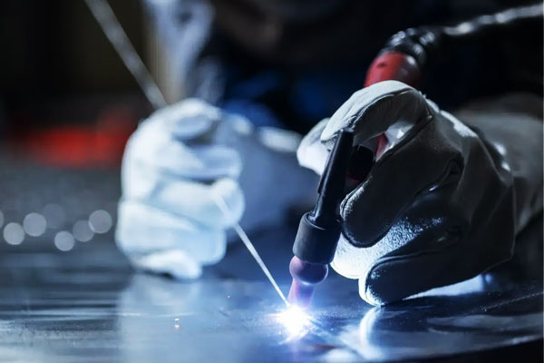
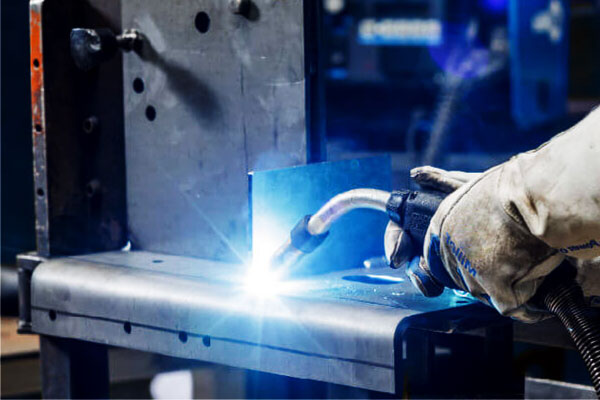
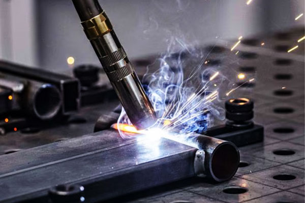
Gazaltı Ark Kaynağı (GMAW / BEN)
GMAW, sürekli beslenen bir sarf tel elektrodu ile iş parçası arasında bir elektrik arkı oluşturur.
Ark koruyucu gaz atmosferini iyonize eder, termal enerjiyi tel ucuna ve iş parçası yüzeyine aktaran bir plazma sütunu üretir.
Metal, akım tarafından belirlenen farklı modlarda telden kaynak havuzuna aktarılır., tel çapı, tel kimyası, Gaz bileşimi ve ark dinamiği:
- Kısa devre aktarımı: erimiş uç iş parçasıyla kısa süreliğine temas eder ve akım artışları damlacıkların hızla ayrılmasına neden olur; damlacık başına enerji düşüktür, Sınırlı nüfuz etme ve minimum ısı girişi sağlar; çok ince saclar için idealdir.
- Küresel aktarım: daha büyük, yerçekiminin etkilediği damlacıklar oluşur ve düşer; bu mod dengesizdir ve sıçrama üretir.
- Sprey transferi: yüksek akım, ince damlacıkların ark boyunca sürekli aktarımı; yüksek birikim ve derin nüfuz ancak daha yüksek ısı girişi (kalın bölümlere daha uygun).
- Darbeli sprey: Darbe başına tek damlacık aktarımı üreten kontrollü tepe ve taban akım dalga biçimi — ince ve orta kalınlıktaki levhalarda iyi bir yüzey elde etmek için düşük ortalama ısı girişini sprey benzeri damlacık ayırma özelliğiyle birleştirir.
Elektromanyetik kuvvetler (çimdik efekti) ve yüzey gerilimi damlacık oluşumunu ve ayrılmasını yönetir.
Kaynak havuzu dinamikleri (sıvı akışı, Kükürt/oksijenden etkilenen Marangoni konveksiyonu, ve elektromanyetik karıştırma) boncuk şeklini ve seyreltmeyi kontrol edin.
Koruyucu gaz bileşimi ark stabilitesini etkiler, metal transfer modu ve penetrasyonu (örneğin, CO₂ damlacık boyutunu ve sıçramayı artırır; argon-oksijen karışımları daha düşük akımlarda sprey transferini stabilize eder).
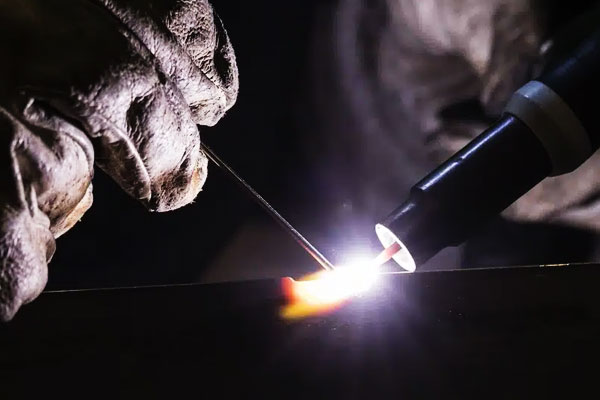
Gaz Tungsten Ark Kaynağı (GTAW / TIG)
GTAW şunu kullanır: tüketilmeyen tungsten elektrot istikrarlı bir arkı sürdürmek için.
Ark daraltılır ve ana metale bağlanır, iyonize gaz yoluyla ısının aktarılması (plazma).
Elektrot tüketilmediğinden, dolgu metali (Kullanılırsa) kaynak havuzuna manuel veya otomatik olarak beslenir.
Temel fiziksel yönler:
- Ark sütunu ve ısı konsantrasyonu: TIG yayları dardır ve oldukça kontrol edilebilirdir; Akım veya torç açısındaki küçük değişikliklerin yerel ısı girdisi üzerinde doğrudan etkisi vardır.
- Ekranlama ve ark kimyası: inert gaz (tipik olarak argon) oksidasyonu önler; alüminyum AC TIG için,
Alternatif polarite oksit temizliği yaratır (elektro parlatma) elektrot pozitif yarı döngü sırasında etki ve elektrot negatif yarı döngü sırasında penetrasyon; bu, dayanıklı alüminyum oksit kabuğunu kırmak için kritik öneme sahiptir. - Isı iletimi ve ışınımlı soğutma: çünkü elektrot daha soğuktur ve ısı iş parçasına akar, TIG, birikinti boyutu üzerinde hassas kontrol sağlayan öngörülebilir bir füzyon bölgesi üretir.
- Ark başlatma ve kararlılık: yüksek frekanslı veya kaldırmayla çalıştırma sistemleri, kirlenme olmadan kontrollü ark başlatmayı sağlar; elektrot seçimi (dikenli, seriasyonlu, lantanlı) farklı akım aralıkları için elektron emisyonunu ve ark stabilitesini uyarlar.
TIG hassas termal kontrole ve minimum erimiş havuz türbülansına izin verir, Ark stabilitesinin ve temizliğin performansa hakim olduğu ince sac ve kozmetik kaynaklar için mükemmel hale getirir.
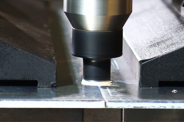
Direnç Nokta Kaynağı (RSW)
Direnç nokta kaynağı bir Joule ısıtma işlemi: Basınçlı elektrot kuvveti yakın teması korurken, temas eden tabaka yığınından yüksek akım geçirilir.
Kontak arayüzünde yerel direnç (ve daha az ölçüde toplu tabaka direnci) elektrik enerjisini hızla ısıya dönüştürür, yerel erimeye ve kaynak külçesinin oluşmasına neden olur.
Önemli mekanik noktalar:
- Temas direnci ve toplu direnç: başlangıç arayüz direnci ısıtmaya hakimdir; Malzemeler yumuşadıkça ve erimiş metal oluştukça, direnç dinamik olarak değişir; süreç kontrolü bu geçişi hesaba katmalıdır.
- Elektrot kuvveti ve ısı dağılımı: basınç kuvveti oksitleri sıkıştırır ve temas direncini azaltır; aynı zamanda erimiş metali kısıtlayarak ve dışarı atmayı önleyerek külçe geometrisini de kontrol eder.
- Termal difüzyon ve soğutma: akım kesildikten sonra, tutma süresi ve elektrot soğutması ısıyı uzaklaştırır ve külçeyi katılaştırır; elektrot soğutma (su soğutmalı bakır elektrotlar) külçe boyutunu ve tekrarlanabilirliğini kontrol etmek kritik öneme sahiptir.
- Malzeme ve kaplama efektleri: kaplamalar (galvanizleme, organik kaplamalar) temas direncini değiştirebilir ve buharlaşabilir, Isı lokalizasyonunu ve elektrot ömrünü etkileyen — programlar buna göre ayarlanmalıdır.
RSW temel olarak elektriğin kullanıldığı elektro-termal-mekanik bir süreçtir., termal ve mekanik değişkenler, metalurjik bir bağ oluşturmak için milisaniyelik zaman ölçeklerinde etkileşime girer.
Sürtünme Karıştırma Kaynağı (FSW)
FSW bir katı hal, termo-mekanik birleştirme işlemi. Dönen bir, profilli araç (omuz + pin) eklem içine daldırılır ve boyunca geçilir.
İş yerindeki mekanizmalar şunları içerir::
- Sürtünmeli ısıtma: Dönen omuz ve pim, takım-iş parçası arayüzünde sürtünme yoluyla ısı üretir, Sıcaklığın yerel olarak plastik olarak akıcı ancak yarı erime durumuna yükseltilmesi.
- Malzeme plastikleştirilmiş akış ve karıştırma: Pimin geometrisi, malzemeyi ön kenardan pimin etrafında akmaya ve ardından sağlamlaşmaya zorlar, boşlukları kapatır ve başlangıçtaki oksit filmlerini parçalayarak ince taneli, dinamik olarak yeniden kristalize edilmiş bir "karıştırma bölgesi" elde edilir.
- Mekanik dövme eylemi: omuz dövme basıncı uygular, karıştırılan malzemeyi sağlamlaştırır ve füzyonla ilgili gözeneklilik olmayan hatasız bir bağlantı üretir.
- Mikroyapısal evrim: şiddetli plastik deformasyon ve dinamik yeniden kristalleşme, taneleri inceltir ve genellikle ergitme kaynaklarıyla karşılaştırıldığında üstün mekanik özellikler üretir.
Çünkü FSW erimeyi önler, katılaşma kusurlarını ortadan kaldırır (örneğin, gözeneklilik, Sıcak Çatlama) ve düşük distorsiyon üretir; Yine de, Başarılı kaynaklama, sağlam destek ve takım geometrisi ile proses kinematiğinin dikkatli kontrolünü gerektirir.
Lazer ışını kaynağı (LBW) & Hibrit Lazer Ark Kaynağı
Lazer kaynağı, enerjiyi yüzeye bağlanan yüksek derecede paralelleştirilmiş bir ışınla iletir, iki ana iletim modunun üretilmesi:
- İletim modu: daha düşük güç yoğunluğunda lazer yüzeyi ısıtır ve malzemeyi iletim yoluyla eritir; nüfuz sığ ve ısıdan etkilenen bölgedir (HAZ) mütevazı.
- Anahtar deliği modu: yüksek güç yoğunluklarında ışın bir metal sütununu buharlaştırarak buharla dolu bir boşluk yaratır (anahtar deliği). Anahtar deliği duvarlarındaki yoğun emilim, anahtar deliği sürdürüldüğü için derin nüfuza neden olur; Anahtar deliği etrafındaki geri tepme basıncı ve akışkan dinamiği, erimiş havuz akışını ve stabilitesini yönetir.
Temel fiziksel faktörler şunları içerir: emilim (malzeme, yüzey durumu), yansıtma (Al ve Cu gibi yüksek derecede yansıtıcı metaller bağlanmayı azaltır), ve anahtar deliği stabilitesi (derz uyumuna ve kirletici maddelerin varlığına karşı hassastır).
Hibrit lazer ark kaynağı, lazeri arkla birleştirir (genellikle MIG) — ark boşluk köprülemeyi iyileştirir, lazer derin nüfuz ve dar HAZ sağlarken bağlantıyı önceden ısıtır ve dolgu maddesi sağlar.
Arkın erimiş metalin kullanılabilirliğini arttırması ve küçük boşluklara karşı hassasiyeti azaltması nedeniyle sinerji ortaya çıkar, Lazer nüfuzu kontrol ederken distorsiyonu azaltır.
Plazma Ark Kaynağı (PENÇE)
PAW, bir plazma gazını zorlayarak daraltılmış bir plazma jeti üretir (argon, hidrojen karışımları) bir tungsten elektrotun etrafındaki ince bir nozül aracılığıyla.
Daralma gaz sıcaklığını ve iyonlaşmayı artırır, odaklanmış bir üretim, her ikisinde de kullanılabilen yüksek enerji yoğunluklu ark:
- Aktarılan mod: Ark iş parçasına bağlanır ve ısı transferi yoğunlaşır; daha derin nüfuz için uygun.
- Aktarılmadı (pilot) mod: Ark, özel ön ısıtma veya ateşleme görevleri için elektrot ile meme arasında sürdürülür.
Plazma jetinin daha yüksek enerji yoğunluğu ve laminer akışı, geleneksel TIG'den daha iyi kontrolle istikrarlı bir penetrasyon sağlar;
gaz kimyası (H₂ ilavesi) duyarlı alaşımlarda potansiyel hidrojen alımı pahasına entalpiyi ve penetrasyonu artırır.
Bu nedenle nozul geometrisi ve gaz akış kontrolü ark şekli için kritik parametrelerdir, penetrasyon ve kaynak havuzu davranışı.
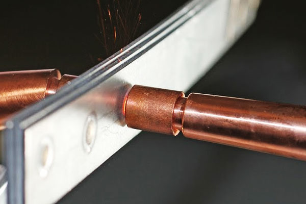
Oksi-yakıt, Lehimleme ve Lehimleme (ince ölçü için, yapısal olmayan)
Bunlar kılcal ve sıcaklık kontrollü birleştirme yöntemleri ergitme kaynağı yerine:
- Oksi-yakıt (alev) kaynak/lehimleme: yanan alev (O₂ + yakıt gazı) lokal ısı sağlar.
Dolgu alaşımının sert lehimlenmesinde (erime noktası ana metalin altında olan) baz metalleri eritmeden bağlantı açıklığına kılcallık yoluyla akacak şekilde ısıtılır.
Alev kimyası ve akı oksit çözünmesini ve ıslanmasını yönetir. Oksi-yakıt kaynağı (füzyon) ana malzemeyi ve dolguyu eritir; kaba ısı kontrolü nedeniyle tabaka işlerinde nadirdir. - Lehimleme: güvenir ıslatma—erimiş dolgu maddesinin akması ve ana metal yüzeylere yapışması gerekir, oksitlerin yerini değiştirme; eritkenler veya kontrollü atmosferler oksitleri giderir ve ıslanmayı destekler.
Kılcal etki dolgu maddesi dağıtımını kontrol eder; Ortak açıklık kritiktir (tipik lehimleme açıklığı 0,05–0,15 mm). - Lehimleme: Lehimlemeye benzer ancak daha düşük sıcaklıklarda (<450 °C); Elektronik ve ışık düzeneklerinde yüzey gerilimi ve katılaşma kontrol bağlantı bütünlüğü.
Çünkü baz metaller eritilmez, Lehimleme ve lehimleme minimum distorsiyona neden olur ve farklı metallerin birleştirilmesine çok uygundur; Başarı dolgunun metalurjisine bağlıdır, akı kimyası ve sıkı temizlik ve temizleme kontrolü.
4. Malzeme Hususları ve Kaynaklanabilirlik
Sac metalin kaynaklanması yaklaşık olarak malzeme davranışı süreç seçimiyle ilgili olduğu için.
Farklı alaşımlar ısınmaya çok farklı tepki verir, dökme, katılaşma ve soğutma:
termal iletkenlik ısının nasıl yayıldığını kontrol eder, alaşım kimyası çatlama duyarlılığını ve kaynak sonrası özellikleri kontrol eder, ve yüzey durumu ark stabilitesini ve gözenekliliği kontrol eder.
| Malzeme grubu | Kaynaklanabilirlik (çarşaf) | Tipik süreçler | Temel kaygılar / etkiler | Tipik dolgu maddesi & koruyucu |
| Karbon çelikler / Alçak alaşım çelikler | İyi → Koşullu | GMAW (kısa devre/darbe), GTAW, RSW | Daha yüksek C veya kalın kesitlerde HAZ sertleşmesi; çarpıtma; Nem/kirletici maddeler mevcutsa hidrojen kaynaklı soğuk çatlama | ER70S-6 (BEN); Ar/CO₂ karışımları; Yüksek CE çelikleri için ön ısıtma/son ısıtma |
| Paslanmaz çelikler (östenitik) | Çok güzel | GTAW, darbeli GMAW, lazer | Hassaslaştırma (karbür yağış) aşırı ısınırsa → korozyon; dar HAZ; distorsiyon kontrolü | ER308L / ER316L (düşük C dolgu maddesi), 100% Ar (TIG), Ar karışımları (BEN) |
| Paslanmaz çelikler (ferritik/martensitik) | Zorlu | TIG, Ön ısıtmalı MIG | Martensitik: HAZ sertleşmesi ve çatlama riski; ferritik: tahıl büyümesi & kırmızlık | Martensitik: eşleşen dolgu + kaynak sonrası temperleme; kontrol ön ısıtma (100–300 ° C) |
Alüminyum & alaşımlar |
İyi — sürece duyarlı | TIG (klima), darbeli ME (makara tabancası), lazer, FSW | Yüksek termal iletkenlik; inatçı oksit (Al₂O₃) kaldırılması gerekiyor; Bazı alaşımlarda gözeneklilik ve sıcak çatlama riski | Alüminyum dolgu maddeleri: ER4043 (Ve, iyi akışkanlık), ER5356 (Mg, daha yüksek güç); 100% Ar veya Ar/He |
| Bakır, pirinç, bronz | Orta → Özel kullanım | TIG, lazer, lehimleme (ince olanlar için tercih edilir) | Çok yüksek iletkenlik (Cu) → ısı kaybı; pirinç Zn dumanı çıkarır; yanma ve buharlaşma riski | Bakır: Cu-Si dolgu maddesi; pirinç: lehim dolgusu; argon koruyucu; iyi havalandırma |
| Galvanizli / kaplamalı çelikler | Duruma bağlı | Yerel şeritli MIG/TIG, RSW (kontrollerle), lazer+ekstraksiyon | Çinko buharlaşır → gözeneklilik, sıçrama ve zehirli dumanlar (metal dumanı ateşi); RSW'de elektrot ömrünün azalması | Kaynak alanında kaplamayı soyun veya yerel ekstraksiyon kullanın; KKD ve duman kontrolü zorunludur |
5. Ortak Tasarım, Montaj ve Kenar Hazırlığı
İyi bağlantı tasarımı, ısı girdisi taleplerini azaltır ve kaliteyi artırır.
- Bindirme bağlantıları punta kaynağında ve sac için MIG'de yaygındır; sıkışmış su veya korozyon ceplerine dikkat edin.
- Alın eklemleri ince levha üzerinde mükemmel kenar hazırlığı gerektirir (kare, boşluğu kapat) lazer veya TIG için. Lazer için kök aralığı genellikle 0–0,5 mm'dir; TIG daha fazlasını tolere edebilir.
- Köşe kaynakları: Güç ve sertlik için, yanmayı önlemek için boğaz boyutunu sınırlayın. Tipik fileto bacağı 1 mm sac ~1–2 mm'dir ancak dikkatli bir şekilde kontrol edilmelidir.
- Kenar eğimleri: İnce levha için genellikle gerekli değildir; Kullanılırsa, Aşırı dolgu ve ısıyı önlemek için eğimi sığ tutun.
- Toleranslar: Lazer ve FSW için, montaj toleransları sıkıdır (±0,1 mm veya daha iyisi). Çok ince malzemelerde MIG/TIG için, boşluklar <0.5 Yanmayı önlemek için mm yaygındır.
6. Isı Girişi, Distorsiyon Kontrolü ve Fikstürleme Stratejileri
İnce sac kolayca bükülür; kontrol stratejileri şunları içerir::
- Daha düşük ısı girişi: darbe kaynağı, daha yüksek seyahat hızı, GMAW'da kısa devre aktarımı, darbeli MIG/TIG.
- Aralıklı dikiş: Stresi azaltmak için boşluklu kaynak parçaları; son geçiş boşlukları doldurur.
- Dengeli kaynak sırası: Simetrik konumları ve geri adım tekniğini kaynaklayın.
- Güçlü fikstür ve raptiyeler: tam kaynaktan önce kelepçeler ve nokta puntolar hareketi azaltır.
- Isı emiciler ve destek çubukları: bakır destek ısıyı dağıtır ve yanmayı önler.
- Ön bükme/aşırı kontrol: kasıtlı olarak ön deformasyona uğratın ve serbest bırakıldıktan sonra düzleşmek için kaynak yapın.
7. Kusur, Temel Nedenler ve Karşı Önlemler
| Kusur | Belirtiler | Kök Nedenler | Karşı önlemler |
| Yanma | Sacdaki delik, yerel erime | Aşırı ısı girişi, yavaş seyahat, ince kesit | Akımı/ısıyı azaltın, seyahat hızını arttır, destek çubuğu, dikiş kaynağı |
| Gözeneklilik | Çukurlar / kaynaktaki gaz delikleri | Kirleticiler, nem, zayıf koruma | Yüzeyleri temizleyin, kuru tel/dolgu, gaz kapsama alanını iyileştirin, arka tarafı temizle |
| Füzyon eksikliği | Kaynaşmamış ayak parmakları veya kökü | Düşük ısı girişi, kötü uyum | Enerjiyi artırın, seyahat hızını azaltın, doğru eklem hazırlığı |
| Çatlama (sıcak/soğuk) | HAZ veya kaynaktaki çatlaklar | Yüksek kısıtlama, hidrojen, hızlı soğutma | Düşük H sarf malzemeleri, ön/son ısıtma, dövme veya stres giderme |
| Aşırı sıçrama | Boncuğun etrafına sıçramak (BEN) | Yanlış aktarım modu / gaz | Darbeli veya kısa devreye geçiş, gaz karışımını ayarlayın |
| Alttan kesilmiş | Kaynak ucundaki oluk | Aşırı voltaj veya seyahat hızı | Voltajı azaltın, yavaş seyahat, meşale açısını ayarlayın |
| Yüzey kirliliği / solma | Oksidasyon, kötü görünüm | Yetersiz koruma veya kirlenme | Korumayı geliştirin, kaynak yapmadan önce temizleyin |
| Nokta kaynak hatası | Sığ veya külçe yok, sınır dışı edilme | Yanlış elektrot kuvveti, akım veya zaman | Sıkma kuvvetini ve mevcut programı ayarlayın, elektrotları değiştirin |
8. Denetleme, Test ve Kalite Güvencesi
Sac kaynağı için kalite uygulamaları:
- Görsel inceleme: kaynak profili, alttan kesilmiş, sıçramak, yüzey süreksizlikleri.
- Boya penetrantı (PT): hassas yüzey çatlak tespiti.
- Ultrasonik (UT): daha kalın tabaka veya çok katmanlı yüzeylerdeki kusurları tespit edebilir.
- Çapraz gerilim testi / soyulma testi: Nokta kaynak mukavemetini nitelendirmek için kullanılır.
- Mekanik testler: çekme, bükülmek, ve temsili kuponlar üzerinde mikro sertlik testleri.
- Boyutlu Kontrol: düzlüğü ve distorsiyonu ölçün; demirbaşlarla veya yeniden işlemeyle düzeltin.
- Süreç kontrol belgeleri: WPS, Geçerli standartlara göre PQR ve kaynakçı nitelikleri.
9. Sac Malzemelerin Kaynağı İçin Pratik İpuçları
Başlamadan önce — hazırlık kontrol listesi
- Malzemeyi tanımlayın & temper. Alaşımı onaylayın (örneğin, 304L vs 304), kalınlık ve kaplamalar. Bilinmiyorsa, örnek ve test.
- Eklemi temizleyin. Yağı/gresi çıkarın, kir, değirmen ölçeği ve ağır oksitler. Alüminyum için oksitleri mekanik olarak çıkarın veya AC TIG oksit temizliğine güvenin. Galvaniz için, Mümkünse çinkoyu hemen kaynak alanından çıkarın.
- Kurulum & raptiye. İnce paneller için her 25-50 mm'de bir punto kaynağı kullanın; daha küçük aralık (10–25 mm) uzun dikişler veya ince dikişler için, esnek parçalar. Kelepçelerin parçaları düz ve hizalı tuttuğundan emin olun.
- Kuru dolgu & sarf malzemeleri. Doldurma telini ve çubuklarını kapalı/kuru tutun; spesifikasyona göre gerekiyorsa fırında elektrotlar.
- Isı kontrolünü planlayın. Destek çubuklarının nerede olduğunu belirleyin, ısı emiciler veya dikiş kaynağı kullanılacaktır. Armatürleri ve termal kelepçeleri hazırlayın.
- Duman kontrolü & KKD. Galvaniz için yerel egzoz, pirinç, paslanmaz; Gerektiğinde solunum cihazları. Göz, işleme uygun el ve vücut koruması.
İşlem & parametre buluşsal yöntemi (başlangıç kuralları)
Bunlar başlangıç noktalarıdır; her zaman yığılmayı yeniden üreten bir kupon üzerinde doğrulayın, kaplama ve sıkıştırma.
GMAW / BEN (ince çelik 0,8–1,5 mm)
- Tel: 0.8 mm ER70S-6.
- Aktarım: ≤1,5 mm için kısa devre; daha yüksek kalite için darbeli.
- Akım: 60–140 A (Düşükten başla, dikkatlice artırın).
- Gerilim: 16–22V.
- Seyahat hızı: 200–600 mm/dak.
- Koruma gazı: 75% Ar/% CO₂ (ekonomik) veya 98% Ar/%2 O₂ (daha iyi ıslatma).
GTAW / TIG (ince paslanmaz & alüminyum)
- Paslanmaz (1.0 mm): DCEN 35–90 A; Ar akışı 8–15 L/dak.
- Alüminyum (0.8–2.0 mm): Ve 60–160 ve; nabız & denge kontrolü faydalı; meşaleyi kullan başlangıçlar (HF veya kaldırma) elektrodu korumak için.
- Tungsten: 1.6DC için –2,4 mm lantanlı/seriyeli, AC için toryumlu veya lantanlı.
Direnç Nokta Kaynağı (0.8 + 0.8 mm yumuşak çelik)
- Elektrot kuvveti: 3–6kN.
- Kaynak akımı: 7-12 (makine & elektrot bağımlı).
- Kaynak süresi: 200–600 ms (şebeke frekansına ve programa bağlı olarak).
- Elektrotların bakımını yapın: Yüzleri düzenli olarak giydirin; Tahribatlı/tahribatsız örnekleme yoluyla külçe boyutunu izleme.
Lazer Kaynak (1.0 mm paslanmaz alın)
- Güç: 1–4 kW seyir hızına bağlı olarak.
- Hız: 1İnce sac için –5 m/dak.
- Odaklanma noktası: 0.2–0.6 mm; mükemmel kenar kalitesi ve sıkı uyum sağlar.
- Geri temizleme: Oksidasyonu önlemek için paslanmaz için argon 5–15 L/dak.
FSW (alüminyum paneller)
- Takım devri: 800–2000 rpm; ilerleme 100–500 mm/dak (hız ve ısı arasındaki değişim).
- Sağlam destek plakası kullanın; Dalma kusurlarını önlemek amacıyla ince sac için kritik takım tasarımı.
Bozulma ve yanmayı kontrol etme
- Düşük ısı girdisi yöntemlerini kullanın: TIG, darbeli ME, Distorsiyon veya görsel görünüm kritik olduğunda lazer veya FSW.
- Kaynak dikişi/atlama: kaynak 10–30 mm, 10–30 mm'yi atla, daha sonra boşlukları doldurmak için geri dönün; bu, yerel ısı oluşumunu sınırlar.
- Denge sırası: parça ve alternatif kenarlar etrafında simetrik olarak kaynak yapın. Dikişler için, Büzülmeyi kontrol etmek için kısa segmentlerde geri adım.
- Sıkıştırma & destek: sert kelepçeler ve bakır destek çubukları ısıyı dağıtır ve yanmayı önler; Kurban destek tabakası çok ince parçalar için etkilidir.
- Ön bükme ve aşırı telafi: öngörülen çarpıklığın tersine kasıtlı olarak hafifçe deforme olur, böylece parça kaynak sonrasında teknik özelliklere göre gevşer.
- Isı emicileri kullanın: Kritik alanların altındaki geçici bakır bloklar veya su soğutmalı armatürler HAZ'ı ve çarpıklığı azaltır.
Raptiye, fikstür ve hizalama ipuçları
- Minimum yapışma boyutu: küçük raptiyeler kullanın (sadece parçayı tutmaya yetecek kadar) ve ardından tam kaynaklarla bitirin. İnce levhalar için 3–6 mm'lik raptiye uzunlukları kullanın.
- Teşekkür ederim sipariş: boşlukları en aza indirmek için raptiyeler yerleştirin; aşırı raptiye aşırı yerel ısınmaya eşit olduğundan fazla raptiye yapmayın.
- Armatür ısıtma: parçalar sıklıkla bozuluyorsa, Termal akışı kontrol etmek için aktif olarak su soğutmalı armatürleri veya seramik pedleri düşünün.
- Hızlı değiştirme paletleri: üretim için, tekrarlanabilir uyumu garanti eden ve çevrim süresini en aza indiren tasarım fikstürleri.
Sarf malzemeleri, takımlama & Bakım
- Elektrot & adam kim: MIG/TIG için kontak uçlarını ve nozulları temiz tutun; aşınmış uçları değiştirin; aşınmış uçlar düzensiz tel beslemesine ve tutarsız arklara neden olur.
- Tel seçimi: tel kimyasını ana metal ve kaplamayla eşleştirin; kuru makaraların bakımını yapın.
- Elektrot pansuman (RSW): Yüz geometrisini düzeltmek için bakır elektrotlar giyin; aşınmış elektrotlar teması azaltır ve akım gereksinimini artırır.
- Meşale açısı & dışarı çıkma: MIG için tutarlı bir şekilde ayrılmayı sürdürün (~10–20 mm tipik) ve uygun torç açısı (10–20 °) Penetrasyon ve boncuk şeklini kontrol etmek için.
10. Proses Seçim Matrisi: Hangi Yöntem Ne Zaman Kullanılmalı?
| Kaynak işlemi | Sac Kalınlığı Aralığı | Malzeme Uygunluğu | Temel Avantajlar | Tipik Uygulamalar |
|---|---|---|---|---|
| GMAW / BEN | 0.8 – 12 mm | Karbon çeliği, paslanmaz çelik, alüminyum | Hızlı, kolay otomasyon, orta ısı girişi | Otomotiv panelleri, endüstriyel muhafazalar, yapısal çerçeveler |
| GTAW / TIG | 0.5 – 6 mm | Paslanmaz çelik, alüminyum, bakır alaşımları | Kesin, temiz kaynaklar, minimum sıçrama | Havacılık, yüksek kaliteli montajlar, dekoratif paneller |
| Direnç Nokta Kaynağı (RSW) | 0.5 – 3 mm | Karbon çeliği, paslanmaz çelik | Çok hızlı, tekrarlanabilir, minimum bozulma | Otomotiv gövde panelleri, cihaz imalatı |
| Sürtünme Karıştırma Kaynağı (FSW) | 1 – 12 mm | Alüminyum, bakır, magnezyum | Katı hal kaynağı, yüksek mukavemet, düşük distorsiyon | Uçak gövde panelleri, gemi gövdeleri, havacılık bileşenleri |
| Lazer ışını kaynağı (LBW) & Hibrit | 0.3 – 6 mm | Paslanmaz çelik, alüminyum, yüksek mukavemetli çelik | Derin penetrasyon, Düşük ısı girişi, yüksek hızlı | Otomotiv, tıbbi cihazlar, hassas düzenekler |
| Plazma Ark Kaynağı (PENÇE) | 0.5 – 6 mm | Paslanmaz çelik, nikel alaşımları, titanyum | Yüksek kaliteli, kontrollü ark, dar HAZ | Havacılık, nükleer, yüksek performanslı bileşenler |
| Oksi-yakıt, Lehimleme, Lehimleme | 0.1 – 3 mm | Bakır, pirinç, ince çelik, kaplanmış metaller | Düşük ısı, farklı metallere katılmak, minimum bozulma | HVAC, elektronik, dekoratif öğeler |
11. Çözüm
Sac metalin başarıyla kaynaklanması, malzemeye uygun işlem kapasitesi gerektirir, ortak ve üretim ihtiyaçları.
Önemli kararlar şunlarla ilgili: ısı yönetimi, ortak uyum, Ve işlem kontrolü. Basit bindirme bağlantılarıyla yüksek hacimler için, direnç nokta kaynağı en ekonomik olanıdır.
Kozmetik dikişler ve onarım çalışmaları için, TIG tercih edilir. Gelişmiş, düşük distorsiyonlu üretim, lazer veya FSW doğru seçim olabilir. Her zaman temsili kuponlarla doğrulayın, kaynak değişkenlerini kontrol etmek, ve denetim ve kalite güvencesini uygulamak.
SSS
Kaynak yapabileceğim en ince sac nedir?
Uygun teknikle (lazer, TIG veya darbeli MIG), sayfalara kadar 0.3–0.5 mm yanma olmadan kaynak yapılabilir. Direnç nokta kaynağı, levha başına ~0,6 mm'lik bindirme bağlantılarında iyi sonuç verir.
Kaynaklı sac montajlarındaki distorsiyonu nasıl azaltabilirim?
Isı girişini en aza indirin (daha yüksek seyahat hızı, darbeli modlar), dengeli kaynak sekansları kullanın, güçlü fikstür ve dikiş kaynağı. Isı emici görevi görmek için destek çubukları ve kelepçeler kullanın.
Farklı metalleri kaynaklayabilir miyim (örneğin, çelikten alüminyuma)?
Çeliğin alüminyuma doğrudan füzyon kaynağı, kırılgan intermetalikler nedeniyle sorunludur. Tercih edilen seçenekler lehimleme, mekanik sabitleme, veya katı hal birleştirme (sürtünme kaynağı veya sürtünme karıştırma tekniği) geçiş katmanları ile.
Galvanizleme gibi kaplamalar kaynağı engeller mi??
Kaplamalar kaynaklamayı zorlaştırır: çinko buharlaşır ve gözenekliliğe ve zehirli dumanlara neden olabilir. Kaynak alanındaki kaplamayı kaldırın veya kaplamalara toleranslı işlemler kullanın (çıkarma ile lazer) ve her zaman duman tahliyesi ve KKD kullanın.
Füzyon kaynağı yerine FSW'yi ne zaman seçmeliyim??
Kullanmak FSW Minimum distorsiyona ihtiyaç duyduğunuz alüminyum alaşımları için, Mükemmel mekanik özellikler, ve dolgu yok. FSW, bağlantı boyunca dönen takıma erişim gerektirir.

