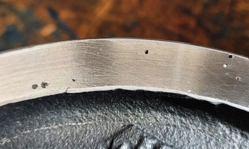
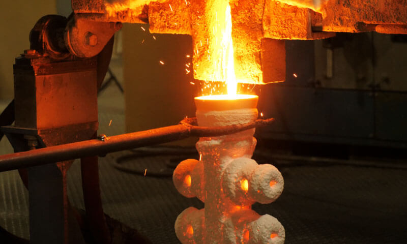
A fellow foundry engineer came to me recently with a problem that had been costing his company for months.
During knockout—the operation where the ceramic shell is broken away from the casting tree—the gating system was fracturing between the first layer of runners and the second layer.
The broken metal pieces were then being struck by the pneumatic chisel and smashing into good castings nearby, causing serious scrap.
His first instinct was to blame the knockout operation. Perhaps the chisel was too aggressive, or the shell was too strong, or the operator was working too fast. All of those are reasonable suspicions, and all of them are wrong.
The breakage was not a knockout problem. It was a solidification problem that the knockout operation simply exposed.
This is one of the most valuable lessons I can pass on to any investment casting engineer: when a gating system breaks in a predictable location, look at the solidification sequence before you look at the knockout tool.
The break is telling you where the metal was weakest, and the metal was weakest where it solidified last without adequate feeding.
I did not have access to his model, so I rebuilt the geometry from his description and ran the simulation myself.
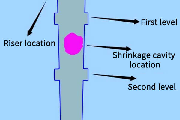
The result was unambiguous: the fracture location was both the last region to solidify in the entire gating system and the region with the highest probability of shrinkage porosity. The break and the shrinkage were in the same place.
This article walks through the diagnosis, the underlying design conflict in multi-layer ring gating systems, the structural modifications that solve it, and the process remedies available when tooling changes are not practical.
1. The Gating System in Question
The system is a sprue–runner configuration with multiple runner layers arranged in a radial, ring-shaped distribution, branching outward like a tree.
This is a common architecture for colata di investimento trees with many parts arranged around a central sprue.
The critical detail is this: the fracture occurs between the first runner layer—the layer closest to the riser end—and the second runner layer.
That location is not random. In a ring-shaped multi-layer tree, every runner layer and every ingate becomes a new thermal mass.
The metal collects there, and what should be a cooling path becomes a hot spot.
The first and second layers sit closest to the riser, so they receive the hottest metal and the most of it. Sono, in effect, the heaviest thermal nodes in the system.
The engineer had used a tapered sprue—larger at the bottom, smaller at the top—with the intention of creating a sequential solidification gradient from the far end (layer 4) toward the riser end (layer 1). It was the right instinct. It was not enough.
2. Why It Breaks Between Layer One and Layer Two
The simulation provided a clear diagnosis: the connection between the first and second runner layers is the last region in the entire gating system to solidify.
This explains both the formation of internal shrinkage defects and the subsequent fracture during knockout.
Sequential Solidification Was Disrupted
The tapered sprue was originally designed to establish a temperature gradient from the far end (Strato 4) toward the riser end (Strato 1). In principle, this arrangement should support directional solidification.
Tuttavia, the actual gating system has a complex, multi-level ring structure. Each runner layer and its ingate connections introduce additional thermal mass.
As molten metal accumulates in these interconnected sections, the region between Layers 1 E 2 becomes a thermal concentration zone.
Di conseguenza, the area intended to follow the planned solidification sequence becomes the slowest-cooling hot spot in the entire system.
The runner is primarily designed to distribute molten metal and help retain slag and inclusions.
Tuttavia, when its geometry creates excessive heat accumulation, it can disrupt the overall temperature gradient.
A uniformly tapered sprue alone cannot compensate for the thermal effects of a multi-level ring arrangement.
The Feeding Channel Was Interrupted Too Early
Durante la solidificazione, thick sections and last-solidifying regions require sufficient liquid metal to compensate for volumetric shrinkage.
In questo caso, when the castings needed to draw molten metal from the runner system to compensate for their contraction, the runner section above them, near the riser end, had already solidified.
The feeding channel was therefore closed before feeding was complete.
Once the connection became isolated from the remaining liquid metal, shrinkage could no longer be adequately compensated. Shrinkage porosity or shrinkage cavities then developed in the region between the two runner layers.
The Possible Back-Suction Effect
Another factor to consider is the potential for a back-suction effect.
When the remote runner sections solidify and contract first, they may draw liquid metal from adjacent runner regions that have not yet completely solidified.
Depending on the solidification sequence and feeding conditions, this can further deplete the already vulnerable connection between Layers 1 E 2.
Di conseguenza, the connection may contain extensive internal shrinkage cavities and porosity.
Although its external appearance may seem acceptable, its actual load-bearing capacity is significantly reduced.
Why the Weak Connection Breaks During Knockout
During shell removal, pneumatic chisels generate repeated mechanical impacts and vibration, which are transmitted through the entire gating assembly.
The connection with the lowest structural integrity is naturally the most likely to fracture.
The problem becomes more severe when the ceramic shell has poor collapsibility or excessive residual strength.
Greater impact force is then required to remove the shell, increasing the mechanical load on the gating system.
A runner connection already weakened by internal shrinkage defects cannot withstand this additional loading.
The pneumatic chisel does not create the underlying defect; it exposes the weakness formed during solidification.
3. The Fundamental Conflict in Multi-Layer Ring Gating Design
Gating system design is a technical discipline in its own right. It consists of the pouring cup, Sprue, corridore, and ingate, and every element must satisfy several basic requirements simultaneously:
- Control filling speed: Ensure smooth, continuous mold filling and minimize turbulence.
- Establish a favorable temperature gradient: Support a controlled solidification sequence and maintain effective feeding.
- Retain slag and inclusions: Prevent impurities from entering the casting cavity.
- Reduce metal consumption: Maintain a reasonable process yield without compromising casting quality.
These requirements are simple to state and difficult to satisfy at the same time in a complex multi-layer ring structure. The difficulty multiplies with every layer added.
The engineer’s original intent—using a tapered sprue to establish sequential solidification—was entirely correct.
The problem is that in a complex multi-layer ring structure, a uniformly tapered sprue is no longer sufficient. The heat concentration from the ring geometry overwhelms the taper’s effect.
4. If the Gating Can Be Modified: Three Directions
The primary objective of modifying the gating system is to establish stable and reliable sequential solidification.
Since simulation identifies the connection between Layers 1 E 2 as the last-solidifying hot spot, the design should focus on either adjusting its solidification behavior or improving its feeding capacity.
Direction One: Optimize the Sprue Taper
Rather than increasing the sprue diameter uniformly, consider a variable cross-section design that provides greater thermal capacity near the riser end.
Per esempio:
- At Layer 4, farther from the riser, the sprue diameter is D.
- Near Layers 1 E 2, the diameter can be increased to approximately 1.3D–1.5D as an initial design reference.
The larger cross-section retains more high-temperature liquid metal near the upper runner levels, helping maintain the feeding connection for a longer period.
Tuttavia, the revised dimensions must be validated through solidification simulation to ensure that the change does not create an undesirable hot spot or excessive metal consumption.
This aligns with the basic principle of gating design: create a favorable temperature gradient for sequential solidification.
Direction Two: Provide Dedicated Riser Necks for Individual Castings
At the junction between each casting’s ingate and the runner, consider introducing a dedicated feeding neck with a rectangular or circular cross-section.
A neck length of approximately 4–5 times its minimum cross-sectional dimension can be used as an initial design reference.
Its purpose is to provide a controlled feeding connection and direct shrinkage toward the designated feeding region rather than allowing defects to develop within the main runner connection.
The neck dimensions and solidification sequence must be evaluated carefully. It should remain effective as a feeding channel for the casting without creating another isolated hot spot.
This is conceptually similar to a “crack-prevention rib” at a casting’s crack-prone location—using local structural optimization to assume and redirect stress.
Direction Three: Adjust the Ingate Position
If the ingate connects directly to the thickest section of the casting, it may increase local heat accumulation and prolong solidification in an already vulnerable area.
Consider relocating the ingate to a relatively thinner section that cools more quickly.
This can help establish a more favorable solidification sequence, allowing the thicker section to remain connected to the runner for feeding as it solidifies.
The revised ingate position must still provide sufficient filling capacity and avoid problems such as turbulence, formazione di ossido, o errori di esecuzione.
The Underlying Design Logic
All three modifications aim to balance feeding performance, integrità strutturale, and process yield.
The ingate and runner connections must have sufficient cross-sectional strength to withstand knockout forces, but excessive dimensions can increase heat accumulation, create new hot spots, and increase metal consumption.
Perciò, gating modifications should not be based on geometry alone. They must consider the casting structure, alloy characteristics, mold conditions, comportamento di riempimento, and solidification sequence.
5. Process-Level Solutions When Major Gating Changes Are Not Practical
Changing an existing gating system can require new tooling, wax-pattern modifications, and production validation.
When a foundry needs to reduce knockout breakage without immediately redesigning the entire system, several process-level measures can be considered.
These methods may reduce the risk, but they do not always eliminate the underlying shrinkage problem.
Use Local Insulation to Keep the Feeding Region Hot
Local insulation, such as ceramic fiber insulation, can be applied around the upper sprue and the region above the first runner level.
The purpose is to slow cooling in the intended feeding region so that it remains liquid longer and continues to supply metal to the lower sections during solidification.
In the example, the original insulation arrangement had not been sufficiently effective because its placement did not adequately support the intended feeding direction.
A more targeted arrangement would focus on the sprue region near the riser and above the first runner level.
The objective is to move the last-solidifying zone upward into a region where shrinkage can be accommodated more safely.
Tuttavia, insulation should not be applied indiscriminately to the entire sprue or gating assembly.
Wrapping the whole structure may alter the thermal balance across all runner levels, potentially creating new isolated hot spots or disrupting the intended feeding sequence.
The insulation layout should therefore be determined using solidification simulation and confirmed through production trials.
Use Local Chills with Caution
Local chills can accelerate cooling in selected regions and help move a hot spot away from a vulnerable connection.
Tuttavia, chills do not eliminate shrinkage by themselves. They generally change the location and timing of solidification.
If a chill moves the last-solidifying region from the original runner junction to another mechanically weak location, the fracture risk may simply be transferred rather than resolved.
Per questo motivo, local chilling should not be used as the primary corrective measure without confirming the new solidification pattern through simulation.
Optimize the Knockout Process
When fracture occurs during shell removal, adjusting the knockout operation is a practical short-term measure.
If the gating system contains a localized weak section, excessive vibration or pneumatic hammer impact can cause it to break even when the casting itself is sound.
Possible adjustments include:
- Reducing the vibration amplitude of the knockout machine.
- Shortening the knockout duration.
- Avoiding direct pneumatic hammer impact on vulnerable runner connections.
- Adjusting the impact direction to reduce bending loads on the gating assembly.
- Improving shell removal efficiency so that less mechanical force is required.
These adjustments can reduce the load applied to the metal assembly and help prevent secondary damage to surrounding castings.
Tuttavia, process adjustments should not be mistaken for a complete solution. If shrinkage porosity remains in the runner connection, the underlying structural weakness still exists.
6. What This Case Teaches
The original design concept of using a tapered sprue to promote sequential solidification was technically sound.
Tuttavia, this case demonstrates that a uniformly tapered sprue alone may not be sufficient for a complex multi-layer ring gating system, where the combined thermal effects of multiple runners and ingates can disrupt the intended solidification sequence.
Three key lessons can be drawn from this case.
Primo, simulare la solidificazione, not just filling.
The original mold flow analysis focused primarily on the filling process, without sufficiently examining solidification behavior and shrinkage formation.
In questo caso, the fracture location coincided with the region where shrinkage defects were predicted.
Filling analysis determines whether molten metal can fill the mold, while solidification analysis identifies potential hot spots, feeding problems, and structurally weak areas.
Secondo, treat the runner as a thermal element, not just a flow channel.
In a multi-layer ring system, every runner section and ingate contributes to the overall thermal field.
Their combined heat accumulation can significantly affect the solidification sequence. Gating design must therefore consider both metal flow and heat distribution rather than relying on sprue taper alone.
Terzo, identify the root cause before blaming the knockout equipment.
When a gating system repeatedly breaks at the same location, the fracture pattern provides important diagnostic evidence.
It may indicate a last-to-solidify region with inadequate feeding and internal shrinkage defects. The knockout chisel exposes the existing weakness; it is not necessarily the source of the problem.
In definitiva, gating system design requires balancing filling control, solidificazione sequenziale, slag retention, and metal consumption.
These requirements often compete with one another. The engineer’s task is to find a practical balance through sound design, simulazione della solidificazione, and production validation.
7. A Few Final Words
His original intent—using a single tapered sprue to achieve perfect sequential solidification—was entirely correct.
The problem was simply that in a complex multi-layer ring structure, a uniformly thickening sprue is no longer sufficient.
The basic requirements of gating system design—controlled filling, solidificazione sequenziale, reduced metal consumption, and slag retention—are all important individually, but in real production they often constrain each other.
The engineer’s task is to find the optimal solution within those constraints.
Rebuilding the simulation myself was also a way of validating the analytical logic.
When the simulation results clearly showed the shrinkage location and the fracture location coinciding, the whole picture became clear.
I hope this analysis helps him organize his thinking and bring the scrap rate down soon.
After all, watching perfectly good castings get destroyed by broken gating pieces during knockout is the most painful thing for anyone in investment casting.
Domande frequenti
Is knockout breakage a knockout problem or a casting problem?
It is a casting problem. A break in a predictable location indicates a solidification and feeding defect. The knockout operation only reveals where the metal was weakest.
Why did the tapered sprue fail to create sequential solidification?
In a multi-layer ring structure, every runner layer and ingate becomes a new thermal mass.
The heat concentration from the ring geometry overwhelms the effect of a uniformly tapered sprue, so the region near the riser becomes the slowest-cooling hot spot instead of solidifying early.
What is the back-suction effect?
If the far end solidifies and contracts first, it can draw metal back from an upper runner layer that has not fully solidified.
This further empties the connection between the first and second layers, making it weaker.
What is a dedicated riser neck and how does it work?
It is a small rectangular or circular channel at the ingate-to-runner connection, with a length about 4–5 times its minimum cross-sectional dimension.
It acts as a heat concentration point, solidifying last so that it feeds the casting and attracts the shrinkage cavity into itself.