মধ্যে বিনিয়োগ কাস্টিং, the wax tree bridges pattern making and shell building. If the tree is assembled poorly, the best wax pattern and the best shell in the world will not save you.
I have seen trees that looked fine on the rack and failed in the autoclave. I have seen trees with perfect spacing but bad gating, and the castings came out with shrinkage porosity that took three days to diagnose.
Wax tree assembly is not just “gluing patterns onto a sprue.” It is the first real gating decision in the process.
It controls metal flow, খাওয়ানো, solidification sequence, shell coverage, dewaxing efficiency, এবং মাত্রিক স্থায়িত্ব.
Get it right, and the rest of the process becomes predictable. Get it wrong, and you will fight defects for the entire production run.
This guide covers the full assembly process—from pre-assembly checks to storage and transport—with the practical data and shop-floor rules I have used for decades.
1. What Is Wax Tree Assembly in Investment Casting?
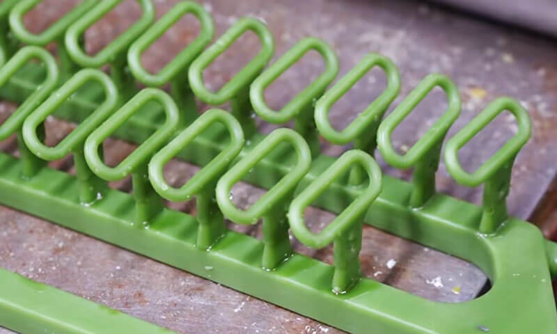
Wax tree assembly is the process of joining individual wax patterns, গেটস, দৌড়বিদ, and a central sprue or pouring cup assembly into a complete wax cluster, commonly called a wax treeor pattern tree.
The assembled tree serves as the pattern for subsequent ceramic shell production. During shell building, the wax tree is repeatedly dipped into ceramic slurry and coated with refractory stucco.
After the shell has dried sufficiently, মোম সরানো হয়, and the remaining ceramic shell forms the cavity into which molten metal is poured.

2. Preparation Before Wax Tree Assembly
The quality of a finished wax tree begins before the first joint is made. Pattern inspection, sprue preparation, tool cleanliness, and environmental control all influence the stability of the assembly process.
Inspect Wax Patterns, স্প্রুস, and Gate Connections
Before assembly, inspect every wax pattern, স্প্রু, and gate component.
Defective patterns should be identified and segregated rather than incorporated into a tree and discovered later.
Pay particular attention to the following conditions:
| Inspection Item | কি চেক করতে হবে | Potential Consequence if Ignored |
| প্যাটার্ন জ্যামিতি | ওয়ারপেজ, বিকৃতি, missing features, and dimensional deviations | Incorrect casting dimensions or incomplete geometry |
| মোম পৃষ্ঠ | ফাটল, বুদবুদ, আঁচড়, দূষণ, এবং পৃষ্ঠের ক্ষতি | Surface defects transferred to the ceramic cavity |
| গেট connection areas | Excess wax, burrs, uneven surfaces, and damaged contact faces | Poor joints, slurry penetration, or shell defects |
| স্প্রু এবং ঢালা head | সমতলতা, সরলতা, ফাটল, এবং মাত্রিক সামঞ্জস্য | মিসলাইনমেন্ট, unstable assembly, and inconsistent gating |
| মোম উপাদান অবস্থা | Excessive softness, ভঙ্গুরতা, বা বিকৃতি | Joint failure or dimensional instability |
The sprue or pouring head deserves particular attention. অনুশীলনে, it is easy to concentrate on the individual patterns and overlook the central sprue.
তবে, a warped or uneven sprue can affect the alignment of every component attached to it.
It can also create uneven joint geometry and make the complete tree difficult to position consistently during shell building.
Before joining, remove wax debris and protrusions from the connection surfaces.
The joining faces should be clean, properly matched, and free from defects that could prevent intimate contact.
Where dimensional requirements are tight, use approved inspection gauges or fixtures to verify the critical dimensions of patterns and sprues rather than relying exclusively on visual judgment.
Prepare Tools and the Work Area
Typical wax tree assembly tools include:
- Temperature-controlled wax welding irons or heated joining tools.
- Clean knives, scrapers, and trimming tools.
- Assembly fixtures, positioning jigs, and alignment gauges.
- Suitable racks or trays for supporting completed trees.
- Approved repair wax and tools for correcting minor joint irregularities.
Tools must be free of accumulated wax, carbonized residue, তেল, এবং অন্যান্য দূষক. Dirty tools can transfer foreign material to the wax surface or introduce particles into joints.
The recommended ambient temperature for the assembly operation in the supplied production procedure is 18–28°C.
This range provides a practical starting point for environmental control, but the actual operating window should be validated for the wax formulation, pattern dimensions, and plant conditions.
Keep the work area clean, শুকনো, and adequately ventilated. Avoid direct sunlight, localized heat sources, strong temperature fluctuations, and dusty conditions.
Excessive heat can soften wax patterns, while temperature changes may cause dimensional movement.
Dust or oil on the pattern surface can interfere with ceramic slurry wetting and contribute to shell defects.
Confirm the Approved Tree Layout and Process Parameters
উৎপাদন শুরু হওয়ার আগেই, confirm the assembly drawing or approved process specification.
The number of patterns per tree, the number of tiers, gate positions, runner dimensions, and pattern orientation should be established according to the casting design.
The correct tree configuration depends on several factors:
- Individual casting size and weight.
- Wall thickness and geometric complexity.
- Alloy and pouring conditions.
- Required production volume.
- Ceramic shell capacity and handling limitations.
- Metal-filling and feeding requirements.
- Available space for dipping, stuccoing, শুকানো, and dewaxing.
Adding more patterns to one tree can improve output per shell and reduce the number of production cycles.
তবে, an overloaded tree may be difficult to handle, can become mechanically unstable, and may compromise shell building or metal feeding.
The objective is not to maximize the number of patterns on each tree. It is to achieve the best balance between production efficiency, শেল গুণমান, filling performance, and casting yield.
3. Wax Tree Assembly Process: ধাপে ধাপে
Wax tree assembly requires repeatable joining techniques and accurate positioning.
Small variations in joint quality, gate angle, or pattern spacing can become significant when multiplied across a large production batch.
ধাপ 1: Position the Sprue and Establish the Reference
Secure the central sprue or pouring assembly in the approved fixture. Check its straightness, vertical alignment, and stability before attaching any patterns.
The sprue acts as the main structural reference for the tree. If it leans or shifts during assembly, the resulting pattern arrangement may become unbalanced or inconsistent.
For repeat production, a dedicated fixture is often worthwhile. It helps maintain the intended pattern orientation, tier height, gate position, and overall tree dimensions, particularly when multiple operators assemble the same part family.
ধাপ 2: Attach the Patterns Using Controlled Wax Welding
Attach each pattern to its designated gate or runner using the approved wax joining method.
The connection should provide sufficient bonding strength without damaging the pattern or distorting its geometry.
Two conditions are especially important:
- Insufficient heat:The joining surfaces may not fuse adequately, leaving a weak interface or a hidden gap.
- অতিরিক্ত তাপ:The wax may melt excessively, causing local collapse, মাত্রিক বিকৃতি, or an enlarged joint.
The correct temperature and contact time depend on the wax material, joint cross-section, tool design, and assembly method.
There is no single universal welding temperature suitable for every pattern system.
During joining, ensure that the connection surfaces are properly aligned and make full contact. Avoid relying on a small wax bridge to hold a large or heavy pattern in position.
After joining, allow the joint to stabilize before applying additional force or attaching adjacent patterns.
ধাপ 3: Inspect and Finish Every Joint
A sound wax joint should be continuous, নিরাপদ, and free from gaps, গর্ত, বা অসম্পূর্ণ ফিউশন.
After joining, remove excess wax with a suitable trimming tool. Smooth irregular protrusions without cutting into the pattern or reducing the required gate cross-section.
Where a small surface depression or gap can be corrected under the approved repair procedure, use compatible repair wax and restore the joint profile.
Do not simply cover a structurally weak joint with a thin layer of wax.
| Joint Defect | Likely Cause | Recommended Correction |
| Visible gap | Poor fit-up or insufficient heat | Rework the joint to obtain full contact |
| দুর্বল বা আলগা connection | Inadequate fusion or insufficient bonding area | Rejoin under controlled conditions and verify stability |
| Excessive মোম buildup | Overheating or poor trimming | Remove excess wax without damaging the joint |
| Distorted প্যাটার্ন কাছাকাছি দ্য joint | Excessive heat or mechanical force | Replace or repair the pattern according to dimensional criteria |
| পিনহোলস বা ছোট গহ্বর | Incomplete fusion, আটকা পড়া বাতাস, বা পৃষ্ঠ দূষণ | Inspect the joint and repair or replace it as appropriate |
A joint that looks smooth is not necessarily strong. For critical or heavy patterns, use an approved mechanical stability check or a validated assembly procedure rather than relying solely on appearance.
ধাপ 4: Arrange Patterns with Adequate Spacing
Pattern spacing determines whether ceramic slurry can reach all required surfaces and whether refractory stucco can form a continuous shell around the tree.
The supplied process guidance specifies a minimum spacing of 10 mm between adjacent wax patterns.
Treat this as a starting requirement for the described process, not a universal rule for all investment casting geometries.
The required clearance must be verified against pattern shape, shell-building materials, স্লারি সান্দ্রতা, stucco particle size, and the ability of the assembly to drain and dry.
Insufficient spacing can lead to:
- Incomplete slurry coverage between adjacent patterns.
- Trapped air or poorly wetted regions.
- Uneven refractory stucco distribution.
- Local shell-thickness variation.
- Difficult wax removal and inadequate shell cleaning.
- Shell cracking or local failure during dewaxing and firing.
Spacing should be checked at the closest points between patterns, not simply between their centerlines or gate connections.
Complex castings with ribs, deep recesses, or protruding features may require more clearance than simple shapes.
একই সময়ে, excessive spacing can increase shell size, ceramic consumption, and the amount of space required in dipping and drying equipment.
The appropriate arrangement is the one that maintains reliable shell coverage while meeting the approved production and gating requirements.
ধাপ 5: Maintain Balanced and Consistent Tree Geometry
Arrange patterns symmetrically where the casting design permits. Distribute the weight around the central sprue, maintain consistent tier spacing, and avoid unnecessary concentrations of heavy components on one side.
An unbalanced tree can be difficult to transport and dip. It may lean during shell building or place uneven mechanical loads on joints and fixtures.
As the ceramic shell dries, movement or distortion can affect shell thickness and dimensional consistency.
For trees containing castings of different sizes or weights, follow the approved layout rather than forcing a perfectly symmetrical arrangement.
Functional requirements—including gating, খাওয়ানো, shell coverage, and access for inspection—take priority over visual symmetry.
ধাপ 6: Verify Gate Orientation and Gating Layout
Gate orientation must follow the approved gating design. The source procedure recommends a downward inclination of approximately 30°–45° between the gate and the main runner for conventional castings.
This range can be a useful initial reference, but it is not an absolute requirement for every casting.
Gate angle and cross-section must be established according to alloy, উপাদান জ্যামিতি, ভরাট আচরণ, and solidification requirements.
For thin-walled or small complex castings, the angle may need to be reduced. Larger or heavier castings may require a different arrangement, subject to the gating design.
A well-designed gate and runner system should:
- Deliver molten metal to the cavity without unnecessary flow restrictions.
- Minimize turbulence and reduce the risk of air or oxide-film entrainment.
- Provide adequate metal supply during filling and solidification.
- Avoid creating unfavorable hot spots or isolated regions that are difficult to feed.
- Allow wax to drain during dewaxing without creating trapped pockets.
The final layout should be based on the foundry’s validated gating design, engineering calculations, simulation where appropriate, and production results.
ধাপ 7: Review Metal Flow and Feeding Requirements
The wax tree must reproduce the intended gating and feeding system accurately.
Pattern assembly should therefore be checked against the expected filling sequence and solidification behavior.
সাধারণভাবে, the gating design should help avoid premature freezing at critical flow paths and support feeding of regions that require additional liquid metal during solidification.
Thick sections and thermal hot spots deserve particular attention because they may be susceptible to shrinkage porosity if feeding is inadequate.
তবে, it is not sufficient to assume that a particular tree arrangement will automatically produce directional solidification.
The result depends on the alloy, বিভাগের বেধ, শেল তাপমাত্রা, তাপমাত্রা ing ালা, gating dimensions, এবং অন্যান্য প্রক্রিয়া ভেরিয়েবল.
The central sprue and runner system must also remain open and adequately sized. Poor joints, excessive wax buildup, or an incorrectly positioned gate can alter the intended flow path.
Before releasing the tree, verify that the assembled layout matches the approved drawing and that no connection has been accidentally blocked or reduced during trimming.
4. Wax Tree Assembly Quality Inspection
Every completed wax tree should undergo inspection before it moves to ceramic shell building.
Inspection is not merely a final visual check; it is a verification that the assembly conforms to the approved process design.
Visual and Surface Inspection
Inspect the entire tree for:
- ফাটল, যুদ্ধ পাতা, missing features, and damaged patterns.
- Loose or incompletely fused joints.
- Gaps, পিনহোল, and excessive wax buildup.
- ধুলো, তেল, wax debris, and other contamination.
- Uneven pattern spacing and inconsistent gate orientation.
- Damage caused during assembly or trimming.
Use adequate lighting and inspect the regions between patterns, around gate junctions, and near the central sprue. These locations are particularly prone to assembly defects.
Structural Stability and Alignment
Gently check the tree for loose patterns and unstable joints. Avoid excessive shaking or force that could damage otherwise acceptable connections.
Verify the following:
| Checkpoint | Acceptance Consideration |
| স্প্রু প্রান্তিককরণ | Within the approved straightness and verticality requirements |
| প্যাটার্ন ওরিয়েন্টেশন | Matches the assembly drawing or process specification |
| Joint শক্তি | No looseness, বিচ্ছেদ, or visible incomplete bonding |
| Tree ভারসাম্য | Stable during normal handling and shell-building operations |
| প্যাটার্ন ব্যবধান | Meets the approved minimum clearance, including the 10 mm reference where applicable |
| গেট কোণ | Consistent with the specified gating design |
| প্যাটার্ন count | Correct number of parts per tree, with no missing or extra components |
Where the tree is large or contains heavy patterns, use suitable support fixtures and handling methods.
A tree should not be accepted simply because it remains upright on a bench; it must also withstand normal transfer and dipping operations without unacceptable movement.
Verify Process Compliance and Traceability
Before release, confirm that the tree corresponds to the correct part number, revision, alloy route, and production batch.
Record the relevant assembly parameters when required, including the number of patterns, tree configuration, operator or work cell, inspection result, and any approved deviations.
For repeat production, standardized work instructions and reference fixtures help reduce operator-to-operator variation.
They also make it easier to investigate defects when a particular tree configuration produces inconsistent shell quality or casting results.
5. Storage and Handling of Assembled Wax Trees
A wax tree that passes inspection can still become nonconforming if it is stored or transported incorrectly.
Wax is sensitive to temperature and mechanical loading, and even slight deformation can affect casting dimensions or the fit of the ceramic shell.
Recommended Storage Conditions
The supplied production procedure recommends storing assembled wax trees for no longer than 48 hoursbefore the next operation.
This should be treated as a plant-specific control target rather than a universal shelf-life limit.
The acceptable holding time depends on wax formulation, pattern geometry, পরিবেশগত অবস্থা, and the dimensional requirements of the casting.
প্রস্তাবিত অনুশীলন অন্তর্ভুক্ত:
- Place completed trees on clean, level racks or dedicated transport fixtures.
- Keep trees in a single layer unless a validated support system allows another arrangement.
- Prevent stacking pressure or contact between adjacent patterns.
- Maintain stable temperature and humidity within the established plant limits.
- Protect the trees from direct sunlight, heaters, and other localized heat sources.
- Keep the storage area clean and free from dust, তেল, and airborne contamination.
- Identify each tree clearly to prevent mix-ups between part numbers or batches.
Avoid assuming that a wax tree remains dimensionally stable simply because no visible deformation has occurred.
সমালোচনামূলক উপাদান জন্য, establish a defined maximum holding time and inspect the tree before shell building if the storage period is extended or environmental conditions have deviated from the process requirements.
Correct Handling and Transportation
Move wax trees carefully and support them at the central sprue, ভিত্তি, or designated fixture. Do not lift a tree by gripping an individual wax pattern, গেট, or thin-walled feature.
Transport equipment should be clean, স্থিতিশীল, and free from sharp edges or protrusions that could scratch or damage the wax.
For heavy or complex trees, use dedicated supports that distribute the load without placing excessive stress on individual joints. Keep movement smooth and avoid sudden impacts, মোচড়, or unnecessary vibration.
After transportation, inspect the tree for loose joints, damaged patterns, and any change in alignment before releasing it to shell building.
6. How to Improve Wax Tree Assembly Consistency in Production
For manufacturers producing investment castings repeatedly, quality depends on turning individual operator skills into a stable, documented process.
Standardize Assembly Fixtures and Work Instructions
Dedicated assembly fixtures can control sprue alignment, pattern position, tier spacing, and gate orientation.
They are particularly useful for complex trees or high-volume orders where repeatability is important.
Work instructions should define:
- Approved tree layouts and pattern counts.
- Critical joint locations and joining methods.
- Required pattern spacing and gate orientation.
- Inspection criteria for joints, প্রান্তিককরণ, এবং পৃষ্ঠের অবস্থা.
- হ্যান্ডলিং, স্টোরেজ, and release requirements.
The goal is to reduce unnecessary variation without preventing operators from identifying genuine defects or escalating unusual conditions.
Control Joining Conditions
Record and validate the important joining parameters for each wax system.
Depending on the method, these may include tool temperature, যোগাযোগের সময়, wax condition, যৌথ জ্যামিতি, and cooling or stabilization time.
If a defect repeatedly appears at the same joint location, inspect the fixture and joint design as well as operator technique.
The problem may be caused by poor access, inadequate contact area, or a connection geometry that is difficult to assemble consistently.
Track Defects and Link Them to Downstream Results
A useful improvement program does not record only whether a wax tree passed inspection.
It also tracks the relationship between assembly conditions and subsequent shell or casting defects.
উদাহরণস্বরূপ:
- Repeated shell defects around a specific joint may indicate poor joint finishing.
- Shell damage near closely spaced patterns may indicate insufficient clearance or drainage.
- Dimensional variation concentrated in one tree position may indicate pattern deformation or inconsistent alignment.
- Repeated handling damage may point to an overloaded tree or inadequate support fixtures.
Reviewing these patterns helps the foundry distinguish assembly-related problems from defects caused by ceramic shell materials, ডিওয়াক্সিং, গুলি, or metal pouring.
7. Frequently Asked Questions About Wax Tree Assembly
What Is the Minimum Spacing Between Wax Patterns?
The production procedure discussed in this guide specifies a minimum spacing of 10 mm between adjacent wax patterns.
This is a useful starting reference, but the actual clearance should be confirmed against the part geometry, সিরামিক স্লারি, stucco আকার, drainage requirements, and shell-building process.
Complex patterns may require greater spacing to ensure complete coating coverage.
What Is the Recommended Angle Between the Gate and Main Sprue?
The reference procedure recommends approximately 30°–45° downward inclinationfor conventional castings.
The appropriate angle depends on the approved gating design, ঢালাই জ্যামিতি, খাদ, ভরাট আচরণ, and feeding requirements.
The range should not replace engineering validation for a specific component.
How Long Can an Assembled Wax Tree Be Stored?
The reference production procedure sets a maximum storage period of 48 ঘন্টা. This should be confirmed for the actual wax system and factory environment.
Stable temperature, proper support, clean storage, and protection from mechanical damage are essential throughout the holding period.
Why Do Wax Tree Joints Cause Ceramic Shell Defects?
Incomplete fusion, ফাঁক, পিনহোল, or excessive wax buildup can change the local surface geometry and interfere with consistent slurry coverage.
Slurry may enter open gaps, while irregular joints can affect drainage and local shell thickness. These conditions can increase the risk of shell defects during drying, ডিওয়াক্সিং, or firing.
Can More Castings Be Added to Each Wax Tree to Reduce Costs?
Only if the tree remains mechanically stable and the approved gating design can deliver the required filling and feeding performance.
Adding patterns without checking spacing, tree mass, shell coverage, and gating capacity may increase scrap and reduce the overall casting yield.
The best configuration is the one that minimizes total manufacturing cost while consistently meeting quality requirements.
8. উপসংহার
Wax tree assembly is much more than connecting individual wax patterns to a central sprue.
It establishes the geometry of the pattern cluster, the quality of the joints, the accessibility of the surfaces during shell building, and the layout of the gating system.
A reliable process begins with sound wax patterns and a straight, stable sprue.
It continues with controlled wax welding, smooth and secure joints, adequate pattern spacing, balanced tree geometry, and a gating arrangement that follows the approved filling and feeding design.
Final inspection, careful handling, and controlled storage then preserve the quality achieved during assembly.
From a foundry engineer’s perspective, the most effective strategy is to prevent defects at the wax stage rather than attempt to correct them after shell building or pouring.
Standardized fixtures, trained operators, consistent inspection, and traceable process controls help reduce avoidable defects, improve casting yield, and maintain repeatable product quality.
For investment casting manufacturers, a well-assembled wax tree is the starting point for a sound ceramic shell and a more reliable final casting.