
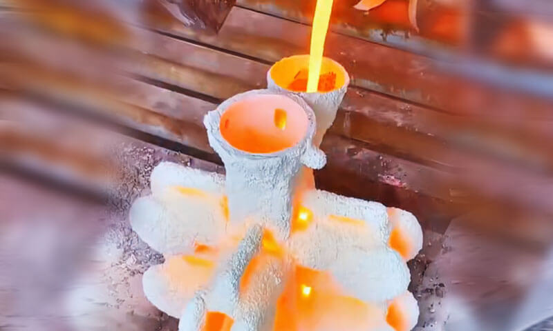
L-ikkastjar jibqa 'wieħed mill-aktar proċessi ta' manifattura ekonomiċi u versatili għall-produzzjoni ta 'komponenti tal-metall kumplessi.
Kemm jekk tuża ikkastjar tar-ramel, ikkastjar ta 'investiment, ikkastjar tal-moffa tal-qoxra, Ikkastjar bil-proċess V, jew mitlufa ikkastjar tal-fowm, funderiji jistinkaw biex jiksbu kkastjar bi preċiżjoni dimensjonali għolja, kwalità interna soda, u finitura tal-wiċċ eċċellenti.
Madankollu, anke f'funderiji moderni mgħammra bi fran tat-tidwib avvanzati, Softwer ta' simulazzjoni, u linji tal-iffurmar awtomatizzati, difetti tal-ikkastjar ma jistgħux jiġu eliminati kompletament.
Id-difetti jistgħu joriġinaw minn mhux xieraq disinn ta' gating u riser, materjali tal-iffurmar mhux adattati, prattiki inadegwati tat-tidwib, kontroll fqir tat-tferrigħ, jew ġestjoni tal-proċess insuffiċjenti.
Jekk mhux identifikat u kkoreġut fil-pront, dawn id-difetti jistgħu jwasslu għal żieda fir-rati tal-fdalijiet, xogħol mill-ġdid għali, skedi ta' produzzjoni mdewma, u affidabilità mnaqqsa tal-prodott.
Il-prevenzjoni tad-difetti b'suċċess teħtieġ li wieħed jifhem il- interazzjoni fost l-imġieba tal-metall imdewweb, karatteristiċi tal-moffa, id-dinamika tas-solidifikazzjoni, u parametri tal-proċess aktar milli tindirizza kull problema b’mod iżolat.
1. Eġittu
Karatteristiċi tad-Difett
A l-Eġittu huwa difett tal-ikkastjar li fih metall imdewweb jonqos milli jimla kompletament il-kavità tal-moffa qabel is-solidifikazzjoni, li jirriżulta f'sezzjonijiet neqsin lokalizzati tal-ikkastjar.
B'differenza difetti jinxtorob, tiġri ħażin matul l-istadju tal-mili tal-moffa, meta l-quddiem tal-metall li javvanza jitlef il-fluwidità u jiffriża qabel ma jilħaq l-estremitajiet tal-kavità.
Misruns huma l-aktar komunement osservati fi:
- Sezzjonijiet tal-ħajt irqiq b'rati għoljin ta 'tkessiħ
- Mogħdijiet twal tal-fluss 'il bogħod mill-ingate
- Kustilji dojoq, xewk, u boxxli
- Porzjonijiet ta 'fuq ta' kkastjar orjentat vertikalment
- Żoni b'bidliet f'daqqa fil-ħxuna tal-ħajt
It-truf mhux mimlija huma tipikament bla xkiel, tond, u nadif, bl-ebda evidenza ta 'ramel iffurmar imwaħħal.
Din il-karatteristika tiddistingwi misrun minn difetti bħal magħluq kiesaħ, fejn żewġ flussi tal-metall parzjalment solidifikati jiltaqgħu iżda jonqsu milli jingħaqdu metallurġikament, tħalli ħjata viżibbli jew linja tal-ħoġor.
F'każijiet severi, karatteristiċi sħaħ tal-ikkastjar jistgħu jkunu assenti, jagħmel il-komponent inutilizzabbli mingħajr tiswija jew sostituzzjoni.
Kawżi Għeruq
Tmexxija ħażina rari hija kkawżata minn fattur wieħed. Minflok, normalment jirriżulta mill-effetti magħquda ta 'fluwidità tal-metall insuffiċjenti, telf eċċessiv tas-sħana, disinn fqir tal-gate, ventilazzjoni tal-moffa inadegwata, u karatteristiċi tal-liga mhux favorevoli.
Parametri tat-tferrigħ mhux xierqa
L-aktar kawża komuni hija nuqqas ta 'qbil bejn it-temperatura tat-tferrigħ u l-veloċità tat-tferrigħ.
Meta t-temperatura tat-tferrigħ tkun baxxa wisq, il-metall imdewweb jitlef is-sħana żejda malajr malli jidħol fil-moffa.
Jekk ir-rata tat-tferrigħ hija wkoll bil-mod wisq — jew l-operazzjoni tat-tferrigħ tiġi interrotta — ix-xifer ta’ quddiem tan-nixxiegħa tal-metall jibda jissolidifika qabel ma l-kavità timtela kompletament.
Kawżi tipiċi relatati mal-proċess jinkludu:
- Temperatura baxxa tat-tferrigħ
- Rata ta 'tferrigħ bil-mod eċċessiv
- Tferrigħ interrott jew inkonsistenti
- Telf eċċessiv tas-sħana waqt it-trasferiment tal-kuċċara
Dawn il-kundizzjonijiet inaqqsu b'mod sinifikanti d-distanza effettiva tal-mili tal-metall imdewweb.
Sistema ta 'Gating ta' daqs żgħir jew iddisinjat ħażin
Is-sistema tal-gate tikkontrolla kemm il-veloċità tal-fluss kif ukoll il-volum tal-metall imdewweb li jidħol fil-moffa.
Jekk il- runner jew ingate żona cross-sectional hija żgħira wisq, tiżviluppa reżistenza għall-fluss eċċessiv, jirrestrinġu l-fluss tal-metall u jżidu l-ħin tal-mili.
Il-mogħdijiet tal-fluss twal jew tortuous inaqqsu aktar it-temperatura tal-metall qabel ma timtela l-kavità.
Kwistjonijiet oħra tad-disinn jinkludu:
- Proporzjon ta' gating mhux xieraq
- Telf ta 'pressjoni eċċessiv
- Distribuzzjoni żbilanċjata tar-runner
- Postijiet ingate inadegwati għal reġjuni ta 'ħajt irqiq
Funderiji moderni spiss jużaw softwer ta’ simulazzjoni tal-ikkastjar biex jottimizzaw il-ġeometrija tal-gating u jbassru postijiet potenzjali ta’ tmexxija ħażina qabel il-produzzjoni.
Fluwidità Fqira tal-Liga
Il-fluwidità tal-metall imdewweb tiddependi mhux biss fuq it-temperatura iżda wkoll fuq kimika tal-liga.
Għal ikkastjar tal-ħadid, baxxi żżejjed ekwivalenti tal-karbonju (CE)—ikkawżat minn karbonju u silikon insuffiċjenti—inaqqas il-fluwidità tal-ħadid imdewweb, jagħmilha aktar diffiċli biex timla kavitajiet kumplessi jew b'ħajt irqiq.
Bl-istess mod, ossidazzjoni eċċessiva, kontenut għoli ta 'inklużjoni, jew modifika mhux xierqa tal-liga tista 'tfixkel il-karatteristiċi tal-fluss u żżid il-probabbiltà ta' solidifikazzjoni prematura.
Backpressure Eċċessiv tal-Moffa
Waqt it-tferrigħ, gassijiet iġġenerati mill-materjali tal-iffurmar għandhom jaħarbu malajr mill-moffa.
Jekk ir-ramel tal-iffurmar fih:
- Umdità eċċessiva
- Kontenut għoli ta 'trab tal-faħam
- Ammonti kbar ta 'legaturi organiċi
- Tafal eċċessiv
l-evoluzzjoni tal-gass tiżdied b'mod sinifikanti. Meta kkombinat ma 'permeabilità ħażina tar-ramel jew venting inadegwat, joħolqu gassijiet maqbuda kontropressjoni li jopponi l-quddiem tal-metall li javvanza, inaqqas il-mili tal-moffa u jżid ir-riskju ta 'tmexxija ħażina.
Din il-problema hija partikolarment komuni f'ikkastjar kbar jew forom b'sezzjonijiet ta 'kavità profonda.
Kap Metallostatiku Insuffiċjenti
Metall imdewweb huwa misjuq permezz tal-kavità minn pressjoni metallostatika, li hija ddeterminata primarjament mill-għoli tal-kolonna tal-metall imdewweb 'il fuq mill-kavità.
Jekk il-garafina ta' fuq (ilaħħqu) huwa baxx wisq jew l-għoli tal-sprue huwa insuffiċjenti, il-pressjoni statika disponibbli tista 'ma tkunx adegwata biex timbotta metall imdewweb fil-bogħod, elevati, jew reġjuni ta 'ħajt irqiq tal-moffa qabel isseħħ is-solidifikazzjoni.
Din il-kwistjoni hija partikolarment kritika għal:
- Ikkastjar kbir
- Forom orjentati vertikalment
- Ikkastjar ta' investiment b'ħajt irqiq
- Kumpless pompa u korpi tal-valvi
Soluzzjonijiet tal-Inġinerija
Il-prevenzjoni ta' misruns teħtieġ ottimizzazzjoni sistematika tal- proċess tat-tferrigħ, Disinn tal-gating, kompożizzjoni tal-liga, u l-karatteristiċi tal-moffa.
Prattiki ta 'inġinerija rakkomandati jinkludu:
Ottimizza l-Parametri tat-Tferrigħ
Żomm it-temperatura tat-tferrigħ fil-medda rakkomandata għal-liga filwaqt li tevita s-sħana żejda eċċessiva li tista 'żżid l-ossidazzjoni jew jinxtorob.
Profil tat-tferrigħ ikkontrollat huwa ġeneralment rakkomandat:
- Bidu bil-mod biex timminimizza t-taqlib
- Mili stabbli u rapidu matul l-istadju prinċipali tat-tferrigħ
- Finitura kkontrollata biex jitnaqqas it-training tal-gagazza
It-tferrigħ kontinwu mingħajr interruzzjoni huwa essenzjali biex tinżamm il-fluwidità tal-metall matul il-mili tal-kavità.
Ittejjeb id-Disinn tas-Sistema tal-Gating
Ikkalkula mill-ġdid iż-żoni tas-sezzjoni trasversali tal-sprue, runners, u ingates biex jiżguraw fluss tal-metall adegwat.
It-titjib fl-inġinerija jista' jinkludi:
- It-tkabbir tas-sezzjonijiet tar-runner u ingate
- Ottimizzazzjoni tal-proporzjonijiet tal-gating
- Tnaqqis tar-reżistenza tal-fluss
- Tqassir tad-distanza tal-mili
- Żieda ta 'ingates addizzjonali għal ġeometriji kumplessi
- Bl-użu ta 'simulazzjoni tal-ikkastjar biex tivverifika l-imġieba tal-mili
Disinn xieraq tal-gating mhux biss jipprevjeni t-tħaddim ħażin iżda wkoll itejjeb ir-rendiment u jnaqqas id-difetti relatati mat-turbolenza.
Ittejjeb il-Fluwidità tal-Liga
Aġġusta l-kompożizzjoni ta 'ċarġ tal-forn biex iżżomm dak speċifikat ekwivalenti tal-karbonju (CE) jew kimika tal-liga.
Għal ħadid griż u duttili, iż-żieda kemxejn tal-karbonju u s-silikon fil-limiti tal-ispeċifikazzjoni tista 'ttejjeb b'mod sinifikanti l-fluwidità tal-metall imdewweb mingħajr ma tikkomprometti l-proprjetajiet mekkaniċi.
Miżuri addizzjonali jinkludu:
- Trattament ta 'tilqim xieraq
- Kontroll tal-inklużjoni
- Tneħħija tal-gagazza qabel tferra
- Iż-żamma tal-metall imdewweb nadif
Ottimizza l-Proprjetajiet tar-ramel tal-iffurmar
Ittejjeb il-permeabilità tal-moffa biex tiffaċilita l-evakwazzjoni tal-gass.
Miżuri effettivi jinkludu:
- It-tnaqqis ta 'żidiet eċċessivi ta' trab tal-faħam
- Kontroll tal-kontenut ta 'umdità
- L-ottimizzazzjoni tal-livelli tat-tafal u tal-legaturi
- Żieda fil-permeabilità permezz ta 'gradazzjoni xierqa tar-ramel
- Żieda ta 'toqob tal-vent jew kanali tal-vent awżiljarju f'żoni kritiċi
Ventilazzjoni tajba tal-moffa timminimizza l-kontropressjoni tal-gass u tippromwovi mili bla xkiel tal-moffa.
Żid Pressjoni Metallostatika
Fejn prattiku, iżżid ir-ras effettiva tal-metall mill:
- Bl-użu ta 'sprue aktar għoli
- Żieda fl-għoli tal-faċċata
- Jgħolli l-elevazzjoni tal-baċin tat-tferrigħ
- L-adozzjoni ta 'sistemi ta' gating minn isfel jew stepped
Il-gting tal-qiegħ huwa partikolarment effettiv minħabba li jipprovdi mili aktar stabbli, inaqqas it-taqlib, jimminimizza l-qbid tal-gass, u jtejjeb il-mili ta 'sezzjonijiet ta' ħajt irqiq.
2. Shorts Għal
Karatteristiċi tad-Difett
A xorts għal huwa difett tal-ikkastjar li fih il-kavità tal-moffa hija mhux mimli kompletament minħabba li volum insuffiċjenti ta 'metall imdewweb jitferra' fil-moffa.
B'differenza a l-Eġittu, li hija primarjament ikkawżata minn fluwidità tal-metall inadegwata jew solidifikazzjoni prematura waqt il-mili, ferra qasir iseħħ meta l-proċess tat-tferrigħ jintemm qabel ma jidħol biżżejjed metall imdewweb fil-kavità.
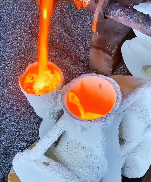
Id-difett tipikament jidher bħala:
- Sezzjoni ta 'fuq mhux kompluta tal-ikkastjar
- Pumijiet nieqsa, flanġijiet, jew uċuħ ta 'fuq
- Livell tal-metall relattivament ċatt ġewwa l-ikkastjar
- Truf kemmxejn arrotondati fil-konfini mhux mimlija
- Il-livell tal-metall imdewweb fil-sprue huwa bejn wieħed u ieħor flush mal-livell tal-metall ġewwa l-kavità tal-ikkastjar
Peress li l-metall imdewweb ma jilħaqx il-volum tal-mili ddisinjat, id-difett normalment jaffettwa l- l-ogħla reġjuni tal-kavità tal-moffa, fejn il-mili komplut jiddependi fuq volum suffiċjenti tat-tferrigħ.
Minn perspettiva ta 'kontroll tal-kwalità, ferra qasir huwa meqjus bħala difett operattiv aktar milli difett metallurġiku jew tal-mili tal-moffa, peress li l-metall imdewweb disponibbli huwa sempliċement inadegwat biex jipproduċi ikkastjar komplut.
Kawżi Għeruq
| Kategorija Kawża | Fattur Speċifiku | Mekkaniżmu |
| Kalkolu ħażin tal-piż | L-operaturi jikkalkulaw ħażin il-piż tal-metall meħtieġ | Metall imdewweb insuffiċjenti fil-kuċċara biex timla l-ikkastjar + gating + Risers |
| Illużjoni tal-mili falza | Kanali dojoq tal-gating b'tferrigħ mgħaġġel | Il-metall ifur mit-tazza tferra qabel ma l-kavità tkun mimlija; l-operatur jiġġudika ħażin l-istat tal-mili |
| Kapaċità tal-kuċċa | Kapaċità żejda insuffiċjenti | L-ebda metall żejjed disponibbli biex jikkumpensa għall-varjazzjonijiet |
Soluzzjonijiet tal-Inġinerija
Prevenzjoni qasir pour tiddependi primarjament fuq ippjanar preċiż tal-proċess u prattiki standardizzati tat-tferrigħ.
Ikkalkula b'mod preċiż il-Piż tat-Tferrigħ
Qabel il-produzzjoni, iddetermina r-rekwiżit totali tal-metall imdewweb billi tikkunsidra l-elementi kollha tas-sistema tal-ikkastjar, inkluż:
- Piż tal-ikkastjar lest
- Sistema ta 'gating
- Risers
- Sezzjonijiet ta' overflow
- Telf tal-proċess
- Allowance tas-sigurtà
Fil-produzzjoni, il-kapaċità tal-kuċċar għandha tipikament tinkludi addizzjonali 10–15% riżerva tal-metall biex tikkumpensa għat-telf tat-trasferimenti, tneħħija tal-gagazza, u varjazzjonijiet operattivi.
Is-simulazzjoni tal-ikkastjar bl-għajnuna tal-kompjuter u l-ippjanar tal-proċess diġitali jistgħu jkomplu jtejbu l-eżattezza tal-piż tat-tferrigħ għal komponenti kumplessi.
Ottimizza l-Operazzjoni tat-Tferrigħ
Għal forom b'sistemi ta' gating relattivament dojoq, ir-rata tat-tferrigħ inizjali għandha tkun ikkontrollata bir-reqqa biex tevita l-overflow prematur mit-tazza tat-tferrigħ.
Sekwenza stabbli tat-tferrigħ tgħin biex iżżomm il-mili kontinwu tal-moffa filwaqt li tippermetti lill-operaturi jissorveljaw il-kundizzjoni attwali tal-mili b'mod aktar preċiż.
Fejn possibbli, sistemi awtomatizzati tat-tferrigħ jistgħu jżommu veloċità konsistenti tat-tferrigħ u jnaqqsu b'mod sinifikanti l-iżbalji relatati mal-operatur.
Istandardizza l-Verifika tal-Mili tal-Moffa
L-operaturi qatt ma għandhom jiġġudikaw il-mili tal-moffa biss billi josservaw it-tazza tat-tferrigħ.
Minflok, il-mili tal-kavità għandu jiġi kkonfermat permezz ta 'monitoraġġ:
- Livell tal-metall fir-risers
- Indikaturi ta' overflow
- Portijiet ta' osservazzjoni (fejn applikabbli)
- Stabbiliti standards tal-ħin tat-tferrigħ
- Sistemi awtomatizzati ta 'monitoraġġ tal-livell għal produzzjoni ta' volum għoli
Proċeduri operattivi standard (SOPs) u taħriġ regolari tal-operaturi huma essenzjali biex jimminimizzaw it-terminazzjoni prematura tal-operazzjonijiet tat-tferrigħ.
3. Tidwib Ħsara Mekkanika
Karatteristiċi tad-Difett
Ikkastjar ħsara mekkanika tirreferi għal ħsara fiżika li sseħħ wara li l-ikkastjar ikun solidifikat, aktar milli difetti ffurmati waqt il-mili jew is-solidifikazzjoni tal-moffa.
Manifestazzjonijiet tipiċi jinkludu truf imlaqqax, kustilji miksura, pumijiet miksura, flanġijiet ikkrekkjati, kantunieri neqsin, u deformazzjoni lokalizzata.
Għalkemm l-ikkastjar innifsu jista 'jkun metallurġikament sod, ħsara mekkanika tista 'tikkomprometti l-eżattezza dimensjonali, integrità strutturali, u kwalità estetika, ħafna drabi jwasslu għal tiswijiet għaljin jew rifjut sħiħ.
B'differenza kavitajiet jinxtorob, xquq, jew misruns, ħsara mekkanika hija kkaratterizzata minn uċuħ ta’ ksur friski bi truf li jaqtgħu, normalment ħielsa mill-ossidazzjoni jew ikkastjar ġilda.
Iż-żoni bil-ħsara ħafna drabi jesponu uċuħ metalliċi nodfa, li jindika li n-nuqqas seħħ waqt operazzjonijiet ta 'wara l-ikkastjar.
L-aktar postijiet vulnerabbli jinkludu:
- Kustilji irqaq u xbieki
- Pumijiet żgħar u lugs tal-immuntar
- Kantunieri li jaqtgħu u karatteristiċi li jisporġu 'l barra
- Sezzjonijiet cantilever twal
- Flanġijiet u truf tal-ħajt irqiq
Ħsara mekkanika l-aktar spiss isseħħ matul:
- Shakeout
- Fttling u tindif
- Tumbling (irfinar tal-kanna)
- Tneħħija ta 'riser u gate
- Immaniġġjar tal-materjal
- Trasport u ħażna
Minħabba li dawn id-difetti joriġinaw wara s-solidifikazzjoni tal-ikkastjar, fil-biċċa l-kbira tagħhom jistgħu jiġu evitati permezz ta 'għażla ta' tagħmir xieraq, disinn tal-għodda, u proċeduri operattivi standardizzati.
Kawżi Għeruq
| Kategorija Kawża | Fattur Speċifiku | Mekkaniżmu |
| Shakeout | Impatt vjolenti waqt shakeout | Forza eċċessiva tikkawża ksur ta 'strutturi dgħajfa |
| Immaniġġjar | Ħabta waqt it-trasport | Ħsara mill-impatt mit-twaqqigħ jew it-tfixkil |
| Irfinar tal-kanna | Tagħbija żejda jew tqabbil mhux raġonevoli tal-parti | Impatt reċiproku u ksur ta 'sezzjonijiet ta' ħajt irqiq |
| Disinn tar-riser | Sezzjoni trasversali ta 'l-għonq ta' riser ta 'daqs kbir | Forza eċċessiva meħtieġa għat-tneħħija; ebda kanal knock-off |
| Tneħħija tar-riser | Direzzjoni li jolqot ħażina | L-istampa vertikali tiġbed u tiċrita l-korp tal-ikkastjar |
Soluzzjonijiet tal-Inġinerija
Il-prevenzjoni tal-ħsara mekkanika tal-ikkastjar teħtieġ ottimizzazzjoni ta ' tagħmir għall-immaniġġjar, disinn riser, operazzjonijiet ta' tindif, u proċeduri ta' xogħol standardizzati.
Adotta Prattiki ta' Shakeout u Tqandil Ikkontrollati
Uża tagħmir ta 'shakeout tal-vibrazzjoni bi frekwenza u amplitudni aġġustabbli biex jaqblu mad-daqs u l-materjal tal-ikkastjar.
Rakkomandazzjonijiet addizzjonali jinkludu:
- Ħalli tkessiħ biżżejjed qabel tħawwad.
- Imminimizza l-għoli tal-waqgħa waqt it-trasferiment.
- Uża tagħmir għall-irfigħ iddisinjat għall-ġeometrija tal-ikkastjar.
- Evita ħabta diretta bejn ikkastjar.
- Aħżen ikkastjar fuq pallets ikkuttunati jew separati fejn xieraq.
Dawn il-miżuri jnaqqsu b'mod sinifikanti t-tagħbijiet tal-impatt fuq karatteristiċi fraġli.
Standardizza l-Operazzjonijiet tal-Irfinar tal-Barmil
Il-parametri tal-irfinar tal-barmil għandhom jintgħażlu skont il-ġeometrija u l-materjal tal-ikkastjar.
L-aħjar prattiki jinkludu:
- Limitazzjoni tal-volum tat-tagħbija tal-barmil biex tevita moviment eċċessiv tal-parti.
- Separazzjoni ta 'kkastjar kbar u żgħar.
- Bl-użu taċ-ċeramika, gomma, jew midja protettiva tal-plastik għal komponenti delikati.
- L-ottimizzazzjoni tal-veloċità tal-barmil u l-ħin tal-ipproċessar.
- Spezzjonar tal-ikkastjar perjodikament matul ċikli twal ta' taqlib.
Għal komponenti kumplessi ħafna jew b'ħajt irqiq, irfinar vibratorju jew shot blasting jistgħu jkunu preferibbli għal tumbling konvenzjonali.
Itejb id-Disinn tal-għonq tar-riser
Disinn ta 'riser xieraq jissimplifika ħafna t-tneħħija sussegwenti.
Miżuri ta 'inġinerija rakkomandati jinkludu:
- Disinn ta 'għonq riser b'sezzjonijiet trasversali mnaqqsa.
- Jinkorporaw skanalaturi knock-off dedikati fl-għerq tar-riser.
- L-iżgurar tal-ħxuna tal-għonq tal-riser hija iżgħar mill-ħajt tal-ikkastjar li jmiss.
- Iż-żamma ta 'tranżizzjonijiet ta' stress bla xkiel biex tevita qsim mhux intenzjonat.
Softwer modern ta 'simulazzjoni tal-ikkastjar jista' jottimizza d-dimensjonijiet tal-riser filwaqt li jżomm prestazzjoni adegwata tal-għalf.
Ittejjeb il-Proċeduri tat-Tneħħija tal-Bieb u Riser
It-tneħħija tar-riser għandha ssegwi proċeduri operattivi standardizzati biex jitnaqqas l-impatt fuq l-ikkastjar.
Metodi rakkomandati jinkludu:
- Applika tagħbijiet tal-impatt tanġenzjali aktar milli perpendikolari mal-wiċċ tal-ikkastjar.
- Uża preses idrawliċi għal separazzjoni kkontrollata fejn possibbli.
- Jimpjegaw srieraq tal-faxxa jew qtugħ li joborxu għal risers kbar.
- Uża oxy-fuel jew qtugħ tal-plażma għall-ikkastjar tal-azzar tqil meta xieraq.
- Evita t-tiswir eċċessiv, partikolarment fuq ikkastjar ta 'preċiżjoni jew b'ħajt irqiq.
Dawn it-tekniki jnaqqsu l-istress lokalizzati u jippreservaw l-integrità tal-ikkastjar.
4. Ħruq fuq ramel u ħruxija tal-wiċċ
Karatteristiċi tad-Difett
Ir-ramel tal-ħruq u ħruxija tal-wiċċ huma tnejn mid-difetti tal-wiċċ tal-ikkastjar l-aktar komuni, it-tnejn li huma jaffettwaw b'mod negattiv id-dehra, eżattezza dimensjonali, effiċjenza tal-magni, u l-kwalità ġenerali tal-komponenti mitfugħa.
Ir-ramel tal-ħruq (imsejħa wkoll bħala ħruq tar-ramel jew penetrazzjoni tal-metall
B'kuntrast, ħruxija tal-wiċċ jiddeskrivi irregolari, wiċċ ikkastjar irregolari li jibqa wara li r-ramel imwaħħal ikun tneħħa
Manifestazzjonijiet tipiċi jinkludu:
- Partiċelli tar-ramel imwaħħlin b'mod qawwi
- Ġilda tal-ikkastjar mhux maħduma jew irregolari
- Pitting lokalizzat
- Penetrazzjoni tal-metall bejn il-ħbub tar-ramel
- Żieda fil-konċessjoni tal-magni
- Prestazzjoni fqira ta 'kisi jew pittura
- Kwalità estetika mnaqqsa
Dawn id-difetti huma speċjalment mhux mixtieqa għal korpi tal-pompa, komponenti tal-valv, partijiet tal-makkinarju ta' preċiżjoni, u kkastjar dekorattiv, fejn il-finitura tal-wiċċ hija rekwiżit ta 'kwalità importanti.
Kawżi Għeruq
Ir-ramel tal-ħruq u l-ħruxija tal-wiċċ ġeneralment jirriżultaw mill-effetti magħquda ta ' proprjetajiet tal-materjal tal-iffurmar, kondizzjonijiet tat-tferrigħ, u l-kwalità tal-preparazzjoni tal-moffa.
Il-mekkaniżmu fundamentali huwa l-interazzjoni eċċessiva bejn il-metall imdewweb u l-wiċċ tal-moffa.
Daqs tal-qamħ tar-ramel oħxon u ebusija baxxa tal-moffa
Id-daqs tal-qamħ tar-ramel tal-iffurmar jinfluwenza direttament il-kwalità tal-wiċċ tal-ikkastjar.
Meta jintuża ramel oħxon eċċessivament, jeżistu vojt akbar bejn il-ħbub tar-ramel li jmissu magħhom.
Taħt il-pressjoni tal-metall imdewweb, metall likwidu jista 'jippenetra dawn il-lakuni u jissolidifika madwar il-partiċelli tar-ramel, jipproduċu penetrazzjoni severa tal-metall u difetti ta 'ħruq.
Bl-istess mod, kompatt insuffiċjenti tal-moffa jew ebusija tal-moffa inadegwata tippermetti li l-ħbub tar-ramel jiċċaqilqu jew jisseparaw waqt it-tferrigħ, tiżdied il-probabbiltà ta 'erożjoni tal-wiċċ u ħruxija.
Umdità Eċċessiva tar-Ramel tal-Moulding
Il-kontenut ta 'umdità għandu rwol kritiku fid-determinazzjoni tas-saħħa tal-moffa u l-kompattabilità.
Meta l-kontenut ta 'umdità huwa għoli wisq:
- Id-densità tal-moffa ssir mhux uniformi.
- L-ebusija tal-wiċċ tonqos.
- Il-ġenerazzjoni tal-fwar tiżdied waqt it-tferrigħ.
- L-erożjoni tal-wiċċ issir aktar probabbli.
L-umdità eċċessiva tnaqqas ukoll ir-reżistenza tal-moffa għall-pressjoni tal-metall imdewweb, promozzjoni tal-penetrazzjoni tal-metall u deterjorazzjoni tal-wiċċ tal-ikkastjar.
Kundizzjonijiet Aggressivi tat-Tferrigħ
Il-parametri tat-tferrigħ jinfluwenzaw b'mod sinifikanti l-interazzjoni bejn il-metall imdewweb u l-moffa.
Kundizzjonijiet li jżidu r-riskju ta 'ħruq jinkludu:
- Temperatura tat-tferrigħ għolja żżejjed
- Pressjoni metallostatika għolja
- Veloċità eċċessiva tat-tferrigħ
- Taqlib qawwi fl-ingate
Metall imdewweb b'temperatura għolja jippossjedi fluwidità akbar u viskożità aktar baxxa, li jippermettilha tinfiltra l-ispazji bejn il-ħbub tar-ramel aktar faċilment.
Fl-istess ħin, fluss turbulenti tal-metall mekkanikament jonqos il-wiċċ tal-moffa, li tirriżulta f'ħsara fil-wiċċ lokalizzata u ġilda tal-ikkastjar mhux maħduma.
Trab tal-Faħam Insuffiċjenti jew Addittivi Karbonaċi
Fl-ikkastjar tar-ramel aħdar, trab tal-faħam iservi funzjoni protettiva importanti.
Waqt it-tferrigħ, it-trab tal-faħam jiddekomponi termalment biex jiġġenera gassijiet li jnaqqsu u film tal-karbonju qawwi rqiq
Jekk il-kontenut tat-trab tal-faħam ma jkunx biżżejjed, il-film tal-karbonju protettiv ma jistax jifforma kontinwament, li jippermetti li metall imdewweb jippenetra l-wiċċ tal-moffa u jaderixxi mar-ramel.
Temperatura tal-Pjanċa tal-Disinn mhux xieraq
It-temperatura tal-pjanċa tal-mudell spiss tiġi injorata iżda għandha influwenza sinifikanti fuq il-kwalità tal-wiċċ tal-moffa.
Jekk il-pjanċa tal-mudell hija eċċessivament sħuna:
- L-umdità ħdejn il-wiċċ tal-moffa jevapora malajr.
- Ir-ramel tal-wiċċ jinxef.
- Is-saħħa tal-moffa tonqos.
- Il-qsim tal-wiċċ isir aktar probabbli.
Bil-maqlub, jekk il-pjanċa tal-mudell hija kiesħa wisq, ramel niedja għandu tendenza li jaderixxi mal-mudell waqt l-irtirar, li tikkawża dmugħ lokalizzat jew tqaxxir tal-wiċċ tal-moffa.
Dawn iż-żoni bil-ħsara jsiru suxxettibbli għall-erożjoni waqt it-tferrigħ, fl-aħħar mill-aħħar jipproduċu uċuħ tal-ikkastjar mhux maħduma.
Soluzzjonijiet tal-Inġinerija
Prevenzjoni effettiva teħtieġ ottimizzazzjoni simultanja ta materjali tal-iffurmar, prattika tat-tferrigħ, u preparazzjoni tal-moffa.
Ottimizza l-Proprjetajiet tar-Ramel
Agħżel ramel tal-iffurmar b'daqs xieraq tal-qamħ filwaqt li żżomm biżżejjed permeabilità.
Miżuri rakkomandati jinkludu:
- Uża ramel bażi fin fejn il-finitura tal-wiċċ hija kritika.
- Żomm distribuzzjoni bilanċjata tal-qamħ tar-ramel.
- Żid il-kompattazzjoni tal-moffa biex tnaqqas il-porożità tal-wiċċ.
- Immonitorja l-ebusija tal-moffa b'mod konsistenti matul il-produzzjoni.
Il-dens, wiċċ moffa uniformi tnaqqas b'mod sinifikanti l-probabbiltà ta 'penetrazzjoni tal-metall.
Żomm l-Addittivi Karboniċi xierqa
Żomm konċentrazzjoni stabbli u effettiva ta 'trab tal-faħam jew addittivi oħra tal-karbonju fir-ramel tal-iffurmar.
Waqt it-tferrigħ, dawn il-materjali jiġġeneraw kontinwu saff tal-karbonju qawwi dak:
- Jipprevjeni kuntatt dirett metall-ramel
- Inaqqas il-penetrazzjoni tal-metall
- Ittejjeb il-finitura tal-wiċċ tal-ikkastjar
- Jiffaċilita t-tħawwid u t-tindif
Għandha ssir analiżi regolari tas-sistema tar-ramel biex tiżgura li l-konċentrazzjonijiet tal-addittivi jibqgħu fil-firxa tal-proċess speċifikata.
Kontroll Molding Ramel Umdità
L-umdità għandha tinżamm fil-medda ottima speċifikata għall-proċess tal-iffurmar.
Għal sistemi konvenzjonali tar-ramel aħdar tal-ħadid griż, il-kontenut ta 'umdità rakkomandat huwa tipikament:
3.0–4.0%
Iż-żamma ta 'umdità stabbli titjieb:
- Saħħa tal-moffa
- Ebusija tal-wiċċ
- Konsistenza tal-kompattazzjoni
- Permeabilità tal-gass
Sistemi awtomatizzati ta 'preparazzjoni tar-ramel jintużaw ħafna f'funderiji moderni biex jiżguraw kontroll konsistenti tal-umdità.
Ottimizza l-Parametri tat-Tferrigħ
Is-sistema ta' gating għandha tkun iddisinjata biex timminimizza t-taqlib u l-impatt dirett tal-metall fuq l-uċuħ tal-moffa.
Prattiki ta 'inġinerija rakkomandati jinkludu:
- Naqqas il-veloċità tat-tferrigħ fejn possibbli.
- Itejb proporzjonijiet gating.
- Tbaxxi t-temperatura tat-tferrigħ għall-valur minimu li xorta jiżgura mili komplut tal-moffa.
- Naqqas il-pressjoni metallostatika eċċessiva.
- Jimpjegaw sistemi ta 'gting tal-qiegħ għal ikkastjar sensittivi.
Kundizzjonijiet ta 'mili stabbli jnaqqsu b'mod sinifikanti kemm l-erożjoni tal-moffa kif ukoll il-penetrazzjoni tal-metall.
Żomm it-Temperatura Approprjata tal-Pjanċa tal-Disinn
It-temperatura tal-mudell għandha tiġi kkontrollata bir-reqqa matul il-proċess tal-iffurmar.
Bħala linja gwida ġenerali, it-temperatura tal-pjanċa tal-mudell għandha tibqa ' kemmxejn ogħla mit-temperatura tar-ramel tal-iffurmar, tippermetti:
- Irtirar faċli tal-mudell
- Qawwa uniformi tal-wiċċ tal-moffa
- Adeżjoni tar-ramel imnaqqsa
- Prevenzjoni ta 'tnixxif eċċessiv tal-wiċċ
It-temperatura tal-mudell konsistenti tikkontribwixxi direttament għal integrità mtejba tal-moffa u kwalità aħjar tal-wiċċ tal-ikkastjar.
5. Inklużjonijiet tar-ramel (Toqob tar-ramel)
Karatteristiċi tad-Difett
Inklużjonijiet tar-ramel, komunement imsejħa toqob tar-ramel, huma ikkastjar difetti li fihom partiċelli tar-ramel tal-iffurmar jinqabdu fi ħdan il-metall imdewweb u jibqgħu inkorporati fl-ikkastjar wara s-solidifikazzjoni.
Jiddependi minn fejn ir-ramel jinqabad, id-difett jista 'jidher jew fuq il-wiċċ tal-ikkastjar jew fil-fond ġewwa l-intern.
L-inklużjonijiet tar-ramel tal-wiċċ huma ġeneralment viżibbli wara shot blasting jew makkinar, Billi inklużjonijiet interni tar-ramel ħafna drabi huma moħbija u jistgħu jiġu skoperti biss permezz Ittestjar radjografiku (RT), Ittestjar ultrasoniku (Ut), tomografija kompjuterizzata (CT), jew sezzjoni distruttiva.
Minħabba li jinterrompu l-kontinwità tal-matriċi tal-metall, inklużjonijiet interni tar-ramel huma partikolarment detrimentali għal komponenti li jżommu l-pressjoni, fejn jistgħu jsiru mogħdijiet ta 'tnixxija jew jibdew xquq ta' għeja taħt tagħbija ċiklika.
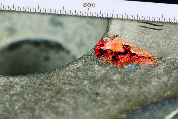
Karatteristiċi tipiċi jinkludu:
- Kavitajiet irregolari mimlija parzjalment jew kompletament bir-ramel tal-iffurmar
- Aħrax, uċuħ ta 'difetti angolari
- Partiċelli tas-silika inkorporati jew materjal tal-moffa
- Porożità lokalizzata assoċjata ma 'ramel maqbud
- Issikkar tal-pressjoni mnaqqsa u saħħa mekkanika
- Makkinabilità fqira minħabba xedd tal-għodda kkawżat minn partiċelli ta 'ramel iebes
L-inklużjonijiet tar-ramel huma fost il- difetti tal-ikkastjar li jiltaqgħu magħhom l-aktar spiss fl-ikkastjar tar-ramel u jibqgħu kawża ewlenija ta 'rifjut għal komponenti kritiċi bħal Korpi tal-valv, Kisi tal-pompa, manifolds idrawliċi, housings tal-kompressuri, u fittings tal-pajpijiet.
Kawżi Għeruq
L-inklużjonijiet tar-ramel joriġinaw meta ramel tal-iffurmar jinqala 'mill-wiċċ tal-moffa jew jiddaħħal fil-kavità tal-moffa, fejn sussegwentement jinbela' mill-metall imdewweb li jnixxi.
Il-formazzjoni tagħhom hija tipikament assoċjata ma 'nuqqasijiet fil-kwalità tal-moffa, disinn tal-mudell, immaniġġjar tal-moffa, jew prestazzjoni tas-sistema gating.
| Kategorija Kawża | Fattur Speċifiku | Mekkaniżmu |
| Saħħa tal-wiċċ tal-moffa | Kontenut insuffiċjenti ta' binder | Qmuħ tar-ramel tal-wiċċ faċilment jinħaslu minn metall imdewweb |
| Disinn tal-mudell | Kantunieri li jaqtgħu mingħajr fletti; angolu tal-abbozz insuffiċjenti | Jikkawża tqattigħ tar-ramel waqt l-irtirar tal-mudell |
| Immaniġġjar tal-moffa | Forom bil-ħsara magħluqa mingħajr tiswija | Żoni bil-ħsara jsiru sorsi tar-ramel |
| Ħażna | Forom maħżuna twil wisq qabel it-tferrigħ | Il-wiċċ jinxef u jitlef is-saħħa |
| Għeluq tal-moffa | Dħul tar-ramel barrani; ramel li jżomm f'wiċċ l-ilma mhux imnaddaf | Ir-ramel jidħol fil-kavità; kikkri għat-tferrigħ mikxufa jippermettu ramel maħlul li jaqa ' |
Soluzzjonijiet tal-Inġinerija
It-tnaqqis tal-inklużjonijiet tar-ramel jeħtieġ kontroll komprensiv ta ' materjali tal-iffurmar, kwalità tal-mudell, preparazzjoni tal-moffa, u fluss tal-metall imdewweb.
Ittejjeb il-Kwalità tar-Ramel tal-Moulding
Ottimizza l-formulazzjoni tar-ramel tal-iffurmar biex tiżgura saħħa adegwata tal-wiċċ matul il-produzzjoni.
Miżuri rakkomandati jinkludu:
- Żomm kontenut ta' tafal jew binder xieraq.
- Imla regolarment ramel frisk biex tistabbilizza l-proprjetajiet tas-sistema tar-ramel.
- Ottimizza l-ħin tat-taħlit tar-ramel u l-kontroll tal-umdità.
- Ittejjeb is-saħħa tal-kompressjoni ħadra u s-saħħa tat-tensjoni mxarrba.
- Immonitorja l-proprjetajiet tar-ramel permezz ta 'ttestjar ta' rutina fil-laboratorju.
Wiċċ tal-moffa aktar b'saħħtu huwa ferm aktar reżistenti għall-erożjoni waqt it-tferrigħ.
Ottimizza Disinn tal-Mudelli u Tiswija tal-Moffa
Disinn tal-mudell ta 'kwalità għolja jimminimizza l-ħsara tal-moffa waqt l-irtirar tal-mudell.
Ir-rakkomandazzjonijiet tal-inġinerija jinkludu:
- Inkorpora angoli ta' abbozz xierqa.
- Disinja fletti ġenerużi f'kantunieri li jaqtgħu.
- Żomm uċuħ tal-mudell lixxi.
- Isewwi ż-żoni kollha tal-moffa bil-ħsara qabel l-assemblaġġ.
- Żgura li s-sezzjonijiet imsewwija jkunu mnixxfa u kkumpatti kif suppost.
Preparazzjoni bir-reqqa tal-moffa tnaqqas il-ġenerazzjoni ta 'ramel maħlul qabel it-tferrigħ.
Imminimizza l-Ħin tal-Ħażna tal-Moffa
Kull meta jkun possibbli, forom għandhom jitferra ftit wara l-preparazzjoni.
Jekk il-ħażna temporanja hija inevitabbli:
- Ipproteġi l-forom minn tnixxif eċċessiv.
- Ikkontrolla l-umdità ambjentali.
- Ipprevjeni l-fluss tal-arja dirett fuq l-uċuħ tal-moffa.
- Spezzjona l-integrità tal-wiċċ qabel tferra.
Iż-żamma tas-saħħa tal-moffa matul il-ħażna tgħin biex tevita l-erożjoni tal-wiċċ waqt il-mili tal-metall.
Neħħi ramel maħlul qabel l-għeluq tal-moffa
Tindif bir-reqqa tal-kavità huwa essenzjali qabel l-assemblaġġ tal-moffa.
L-aħjar prattiki jinkludu:
- Blow il-kavità nadif billi tuża arja kkompressata.
- Vakwu ramel maħlul minn bwiet fil-fond.
- Spezzjona ż-żoni msewwija bir-reqqa.
- Għatti immedjatament il-baċin tat-tferrigħ wara l-għeluq tal-moffa biex tevita l-kontaminazzjoni minn ramel jew debris fl-arja.
Proċeduri ta 'manutenzjoni stretti jnaqqsu sostanzjalment ir-riskju li materjal barrani jidħol fil-moffa.
Ottimizza s-Sistema tal-Gating u Installa Filtri taċ-ċeramika
Sistema ta 'gating iddisinjata tajjeb timminimizza t-taqlib u l-erożjoni tal-moffa.
It-titjib rakkomandat jinkludi:
- Naqqas il-veloċità tal-metall f'postijiet kritiċi.
- Elimina l-impatt dirett fuq il-ħitan tal-moffa.
- Ottimizza runner u ingate ġeometrija.
- Tippromwovi bla xkiel, mili tal-moffa laminari.
Għal kkastjar ta 'kwalità għolja, filtri tal-fowm taċ-ċeramika għandhom jiġu installati fis-sistema tal-gate. Dawn il-filtri jaqbdu b'mod effettiv:
- Partiċelli tar-ramel maqtugħin
- Gagazza
- Films ta' l-ossidu
- Inklużjonijiet mhux metalliċi
qabel ma jidħlu fil-kavità tal-ikkastjar, ittejjeb b'mod sinifikanti l-indafa interna u tnaqqas ir-rati tal-fdalijiet.
6. Nefħa tal-vini u tal-moffa
Karatteristiċi tad-Difett
Vini (magħrufa wkoll bħala flash, finning, jew flash tal-linja tal-firda) u nefħa tal-moffa huma żewġ difetti komuni ikkastjar assoċjati ma deformazzjoni tal-moffa taħt l-effetti magħquda tal-pressjoni tal-metall imdewweb u t-temperatura elevata.
Għalkemm iż-żewġ difetti joriġinaw minn riġidità jew saħħa insuffiċjenti tal-moffa, huma differenti fid-dehra u l-mekkaniżmu tal-formazzjoni.
Vini hija kkaratterizzata minn irqiq, sporjezzjonijiet irregolari tal-metall bħal folja testendi 'l barra mill-wiċċ tal-ikkastjar.
Dawn l-isporġenzi huma ġeneralment perpendikolari mal-wiċċ u l-aktar spiss iseħħu tul il- linja tal-firda, ġonot tal-qalba, jew xquq tal-moffa.
Minħabba li l-metall imdewweb jippenetra fetħiet dojoq maħluqa minn separazzjoni tal-moffa jew espansjoni termali, il-flash li jirriżulta huwa tipikament irqiq, jaqtgħu, u irregolari fil-ħxuna.
Nefħa tal-moffa, b'kuntrast, jidher bħala nefħa lokalizzati jew sporġenzi fit-tond jew fuq l-uċuħ interni jew esterni tal-ikkastjar.
Pjuttost milli jiffurmaw xewk irqaq, nefħa tirriżulta minn deformazzjoni tal-plastik jew spostament 'il barra tal-ħajt tal-moffa taħt pressjoni metallostatika, produzzjoni ta 'sezzjonijiet ta' daqs eċċessiv jew forma irregolari fuq l-ikkastjar lest.
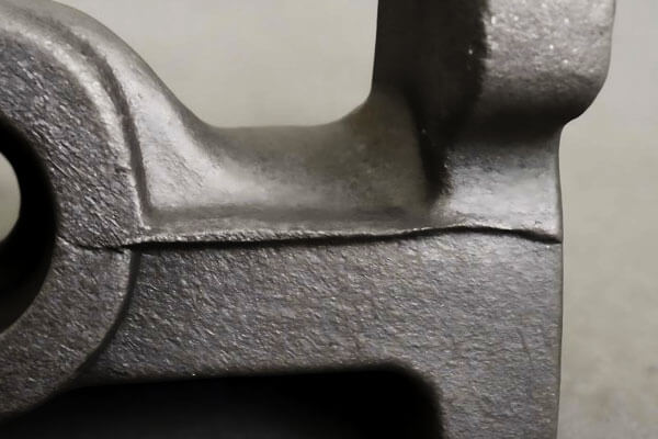
Karatteristiċi tipiċi jinkludu:
- Xewk irqiq metalliċi tul uċuħ tal-firda (veining/flash)
- Projezzjonijiet projezzjonijiet nodulari jew projezzjonijiet lokalizzati (nefħa tal-moffa)
- Żieda fid-dimensjonijiet tal-ikkastjar lil hinn mit-tolleranzi tad-disinn
- Rekwiżiti eċċessivi ta 'fetling u tħin
- Preċiżjoni dimensjonali mnaqqsa
- Spejjeż ogħla tal-magni minħabba t-tneħħija tal-materjal żejjed
Filwaqt li dawn id-difetti spiss jistgħu jitneħħew waqt l-irfinar, dawn iżidu l-ispejjeż tal-produzzjoni u jistgħu jikkompromettu l-preċiżjoni dimensjonali meħtieġa għall-komponenti mmaxinjati jew immuntati.
Kawżi Għeruq
Il-vini u t-nefħa tal-moffa ġeneralment jirriżultaw minn taħlita ta 'saħħa insuffiċjenti tal-moffa, kompattazzjoni inadegwata, umdità eċċessiva, u pressjoni eċċessiva eżerċitata minn metall imdewweb waqt it-tferrigħ.
| Kategorija Kawża | Fattur Speċifiku | Mekkaniżmu |
| Kumpatt tal-moffa | Kumpatt tal-moffa insuffiċjenti jew irregolari | Żoni lokali tar-ramel maħlul jiddeformaw u jespandu taħt pressjoni statika tal-metall |
| Ramel tal-iffurmar | Saħħa insuffiċjenti tar-ramel tal-wiċċ jew umdità għolja | L-umdità għolja tnaqqas is-saħħa mxarrba f'temperatura għolja; is-saff tal-wiċċ jagħti taħt sħana/pressjoni |
| Kondizzjonijiet tat-tferrigħ | Pressjoni metallostatika eċċessiva u veloċità tat-tferrigħ | Il-mili mgħaġġel tal-metall jikkawża żieda qawwija fil-pressjoni tal-kavità; timbotta l-ħajt tar-ramel 'il barra |
Soluzzjonijiet tal-Inġinerija
Il-prevenzjoni tal-vini u t-nefħa tal-moffa teħtieġ titjib preparazzjoni tal-moffa, kwalità tar-ramel, Disinn tal-gating, u rinfurzar strutturali.
Ittejjeb il-Kwalità tal-Kompattazzjoni tal-Moffa
Ottimizza l-parametri tal-iffurmar biex tikseb kompattazzjoni konsistenti u uniformi fil-moffa kollha.
Prattiki rakkomandati jinkludu:
- Żid l-ebusija ġenerali tal-moffa.
- Elimina reġjuni lokalizzati tar-ramel maħlul.
- Żomm pressjoni ta 'kompattazzjoni konsistenti.
- Ivverifika regolarment l-ebusija tal-moffa billi tuża metodi ta 'ttestjar standardizzati.
- Żgura l-allinjament xieraq tal-garafina qabel ma tagħlaq il-moffa.
Id-densità uniformi tal-moffa ttejjeb b'mod sinifikanti r-reżistenza għad-deformazzjoni waqt it-tferrigħ.
Ottimizza l-Proprjetajiet tar-ramel tal-iffurmar
Ittejjeb il-prestazzjoni f'temperatura għolja tar-ramel tal-iffurmar billi tikkontrolla kemm il-kompożizzjoni kif ukoll l-umdità.
Miżuri ewlenin jinkludu:
- Aġġusta l-kontenut tal-legaturi u tat-tafal b'mod xieraq.
- Żomm l-umdità fil-firxa tal-proċess speċifikata.
- Ittejjeb is-saħħa tat-tensjoni fl-imxarrab f'temperatura għolja.
- Ottimizza l-ħin tat-taħlit tar-ramel u d-distribuzzjoni tal-addittivi.
- Immonitorja regolarment il-proprjetajiet tas-sistema tar-ramel permezz ta 'ttestjar tal-laboratorju.
Wiċċ tal-moffa aktar b'saħħtu jiflaħ aħjar it-tagħbija termali u mekkanika.
Itejb il-Kondizzjonijiet tal-Gating u t-Tferrigħ
It-tnaqqis tal-pressjoni eċċessiva tal-kavità huwa wieħed mill-aktar metodi effettivi biex tiġi minimizzata d-deformazzjoni tal-moffa.
It-titjib fl-inġinerija jinkludi:
- Naqqas il-veloċità tat-tferrigħ fejn prattiku.
- Itejb proporzjonijiet gating.
- T'isfel tar-ras metallostatika eċċessiva.
- Iddisinja mogħdijiet tal-fluss tal-metall aktar lixx biex tnaqqas it-taqlib.
- Uża sistemi tal-qiegħ fejn xieraq biex tistabbilizza l-mili tal-kavità.
Id-disinn tal-gating xieraq iqassam il-pressjoni b'mod aktar uniformi u jimminimizza t-tagħbija tal-moffa lokalizzata.
Issaħħaħ is-Sezzjonijiet Kritiċi tal-Mould
Għal kbir, tqil, jew ikkastjar tal-ħajt oħxon, appoġġ strutturali addizzjonali għandu jiġi inkorporat fis-sistema tal-moffa.
Metodi ta 'rinfurzar rakkomandati jinkludu:
- It-tisħiħ ta 'sezzjonijiet tal-moffa vulnerabbli b'vireg ta' rinfurzar jew strutturi ta 'appoġġ.
- Żieda fir-riġidità tal-garafina.
- L-użu ta 'bard fejn xieraq biex iħaffef is-solidifikazzjoni lokali u tnaqqas it-tul tal-pressjoni.
- Tissaħħaħ il-qlub kbar b'appoġġi interni jew chaplets meta meħtieġ.
Dawn il-miżuri jgħinu biex tinżamm il-ġeometrija tal-kavità matul it-tferrigħ u s-solidifikazzjoni.
7. Moffa Lift (Irfigħ tal-garafina) u Runout
Karatteristiċi tad-Difett
Lift tal-moffa, magħrufa wkoll bħala irfigħ tal-garafina jew ilaħħqu lift, huwa difett serju tal-ikkastjar li fih il- moffa ta 'fuq (ilaħħqu) hija sfurzata 'l fuq waqt it-tferrigħ, ħolqien ta 'vojt fil-pjan tal-firda bejn il-faċċata u tkaxkir.
Metall imdewweb imbagħad jippenetra dan il-vojt, jipproduċi flash eċċessiv u jikkawża li l-ikkastjar jaqbeż id-dimensjonijiet maħsuba tiegħu.
F'każijiet severi, is-separazzjoni ssir kbira biżżejjed biex il-metall imdewweb jaħrab mill-kavità tal-moffa. Dan il-fenomenu huwa magħruf bħala runout (jew tnixxija tal-metall).
Ir-runout huwa wieħed mid-difetti l-aktar perikolużi fil-produzzjoni tal-funderija minħabba li mhux biss jirriżulta f'falliment sħiħ tal-ikkastjar iżda joħloq ukoll riskji sinifikanti għas-sikurezza għall-persunal u t-tagħmir minħabba r-rilaxx mhux ikkontrollat ta 'metall imdewweb f'temperatura għolja..
Karatteristiċi tipiċi jinkludu:
- Kbir, flash kontinwu tul il-linja tal-firda
- Żieda fil-ħxuna tal-ikkastjar jew dimensjonijiet ta 'daqs eċċessiv
- Separazzjoni viżibbli bejn ilaħħqu u tkaxkir
- Tnixxija tal-metall imdewweb mill-moffa
- Mili mhux komplut ikkawżat minn telf ta 'metall imdewweb
- Ossidazzjoni severa tal-wiċċ u kontaminazzjoni ħdejn żoni ta 'tnixxija
Ladarba sseħħ runout, il-metall imdewweb li jifdal ġewwa l-kavità jista 'jkun insuffiċjenti biex jitlesta l-mili, spiss iwassal għal difetti sekondarji bħal misruns, pours qosra, kavitajiet jinxtorbu, u distorsjoni dimensjonali.
Kawżi Għeruq
Moffa lift u runout jseħħu meta l- forzi 'l fuq iġġenerati waqt it-tferrigħ jaqbżu l-forza ta' trażżin li żżomm in-nofsijiet tal-moffa flimkien.
L-okkorrenza tagħhom hija ġeneralment assoċjata ma 'nuqqasijiet fl-ikklampjar tal-moffa, prattika tat-tferrigħ, jew preċiżjoni tal-għodda.
| Kategorija Kawża | Fattur Speċifiku | Mekkaniżmu |
| Ikklampjar/ippeżar | Kklampjar jew piż insuffiċjenti | Qfil tal-garafina maħlula; piżijiet tal-istampa insuffiċjenti; tneħħija prematura tal-piżijiet qabel is-solidifikazzjoni |
| Tferra impatt | Veloċità eċċessiva tat-tferrigħ | Forza dinamika kbira 'l fuq taqbeż il-forza taż-żamma tal-piżijiet tal-istampa |
| Pjanċa tal-mudell | Pjanċa tal-mudell warped | Tajjeb ħażin tal-pjan tal-firda; tħalli vojt għal tnixxija tal-metall |
Soluzzjonijiet Korrettivi
- Peżar xieraq: Ikkalkula l-piż tal-istampa meħtieġ skont iż-żona proġettata tal-ikkastjar u r-ras metallostatika; neħħi l-piżijiet tal-istampa biss wara li l-ikkastjar ikun issolidifikat bis-sħiħ; uża klampi tal-garafina għall-illokkjar awżiljarju.
- Naqqas l-impatt tat-tferrigħ: Niżżel il-pożizzjoni tat-tferrigħ tal-kuċċa; tnaqqas il-veloċità tat-tferrigħ biex tnaqqas il-forza tal-impatt 'il fuq fuq il-moffa ta' fuq.
- Żomm pjanċi tal-mudell: Spezzjona regolarment il-flatness tal-pjanċi tal-mudell; issewwi jew ibdel pjanċi tal-mudell mgħawweġ u deformati fil-ħin.
- Peżar f'diversi punti: Għal kkastjar kbar, tadotta piż uniformi b'ħafna punti biex tevita l-irfigħ lokali tal-moffa ikkawżat minn pressjoni żbilanċjata.
- Disinn tal-garafina: Żgura li d-disinn tal-flask jipprovdi riġidità adegwata u punti tal-ikklampjar għall-piż u l-pressjoni speċifiċi tal-ikkastjar.
8. Tabella fil-qosor: Difetti u Soluzzjonijiet
| Difett | Kawżi Għeruq Primarji | Soluzzjonijiet Ewlenin |
| Eġittu | Temperatura baxxa tat-tferrigħ; fluwidità fqira; ras metallostatiku insuffiċjenti | Żid it-temperatura tat-tferrigħ; ottimizza gating; ittejjeb il-fluwidità tal-liga; żid l-għoli tal-garafina |
| Shorts Għal | Piż tal-metall insuffiċjenti; illużjoni tal-mili falza | Kalkolu preċiż tal-piż; tistandardizza l-proċedura tat-tferrigħ; 10-15% metall żejjed |
| Ħsara Mekkanika | Shakeout vjolenti; tneħħija żbaljata tar-riser; immaniġġjar ħażin | Immaniġġjar ġentili; disinn xieraq ta 'riser; teknika korretta tat-tneħħija; irfinar ottimizzat |
| Ħruq fuq/Ħruxija | Ramel oħxon; ebusija baxxa tal-moffa; temperatura għolja tat-tferrigħ | ramel ifjen; kompattazzjoni aħjar; trab tal-faħam ottimizzat; umdità kkontrollata; gating imtejjeb |
Inklużjonijiet tar-ramel |
Saħħa baxxa tal-moffa; difetti fil-mudell; ramel barrani | Formulazzjoni tar-ramel ottimizzata; kwalità mtejba tal-mudell; tindif tal-kavità; filtri taċ-ċeramika |
| Vin/nefħa | Kumpatt fqir; ramel dgħajjef; pressjoni eċċessiva | Kumpatt aħjar; saħħa tar-ramel imtejba; Gating ottimizzat; tisħiħ lokali |
| Moffa Lift/Runout | Peżar insuffiċjenti; impatt eċċessiv; mudell mgħawweġ | Peżar xieraq; impatt imnaqqas; manutenzjoni tal-mudell; peżar f'ħafna punti |
9. Konklużjoni
Il-prevenzjoni u l-kontroll tad-difetti tal-ikkastjar huwa kompitu sistematiku ta 'inġinerija li ma jistax jiġi solvut billi jiġi aġġustat parametru wieħed tal-proċess.
Is-seba 'difetti komuni analizzati hawn fuq ikopru r-rabtiet ewlenin kollha tal-produzzjoni tal-ikkastjar tar-ramel: disinn tal-mudell, preparazzjoni tar-ramel tal-iffurmar, Disinn tal-gating, operazzjoni tat-tferrigħ u tindif ta 'wara l-ikkastjar.
Ħafna difetti jistgħu jiġu evitati b'mod effettiv permezz ottimizzazzjoni tal-proċess 'il quddiem, operazzjoni standardizzata fuq il-post u monitoraġġ tal-parametri tal-proċess f'ħin reali, aktar milli wara r-rimedju wara li sseħħ l-iskrappjar.
Key Takeaways
- Id-difetti huma interkonnessi: L-indirizzar ta’ difett wieħed jista’ jaffettwa lil oħrajn; approċċ olistiku huwa essenzjali.
- Il-prevenzjoni hija aħjar mill-kura: L-ottimizzazzjoni 'l quddiem u l-kontroll tal-proċess huma aktar effettivi mill-għażla ta' wara l-ispezzjoni.
- Titjib immexxi mid-data: Track rati ta 'difetti, janalizza xejriet, u timplimenta ċikli ta' titjib kontinwu.
- Taħriġ għall-operaturi: Operaturi tas-sengħa li jifhmu l-mekkaniżmi tad-difetti huma kritiċi għall-kwalità.
- Standardizzazzjoni tal-proċess: Konsistenti, proċeduri dokumentati jnaqqsu l-varjazzjoni u jipprevjenu rikorrenza.
Il-funderiji għandhom jistabbilixxu mekkaniżmu ta 'analiżi tad-difetti b'ċirku magħluq: jikklassifika u jgħodd it-tipi ta' difetti, traċċa lura għall-kawżi ewlenin mill-karatteristiċi tad-dehra, u jivverifika l-effetti tat-titjib permezz ta 'testijiet tal-proċess.
L-ottimizzazzjoni tal-kwalità kontinwa bbażata fuq id-dejta mhux biss tnaqqas ir-rata ta 'rifjut u l-ispiża tal-produzzjoni, iżda wkoll jistabbilixxu pedament sod għall-produzzjoni ta 'ikkastjar ta' grad għoli u ta 'valur miżjud għoli.
FAQs
X'inhi d-differenza bejn misrun u short pour?
Misrun huwa kkawżat minn solidifikazzjoni prematura qabel ma jitlesta l-mili tal-kavità (fluwidità/kwistjoni termali).
It-tferrigħ qasir huwa kkawżat minn volum tal-metall totali insuffiċjenti (kwistjoni ta 'piż/kwantità). Misrun jaffettwa sezzjonijiet irqaq speċifiċi; ferra qasir taffettwa s-sezzjoni ta 'fuq kollha.
Għaliex l-inklużjonijiet tar-ramel iseħħu anke b'ramel tal-iffurmar tajjeb?
L-inklużjonijiet tar-ramel jistgħu jirriżultaw minn difetti fil-mudell (kantunieri li jaqtgħu, abbozz insuffiċjenti), forom bil-ħsara magħluqa mingħajr tiswija, ramel barrani mit-tindif, jew ramel maħsul mill-wiċċ waqt it-tferrigħ.
Anke ramel tajjeb ma jistax jikkumpensa għal dawn il-kwistjonijiet.
Kif nista 'niddistingwi bejn l-inklużjoni tar-ramel u l-inklużjoni tal-gagazza?
L-inklużjonijiet tar-ramel fihom ħbub tar-ramel angolari u huma tipikament kannella/griż.
Gagazza inklużjonijiet huma tal-ħġieġ, jiskuraw, u ħafna drabi jkollhom kompożizzjoni metallika differenti (ossidi, silikati).
L-inklużjonijiet tar-ramel għandhom tendenza li jkunu irregolari; l-inklużjonijiet tal-gagazza spiss jidhru lixxi, partiċelli tal-ħġieġ.
X'inhu l-aktar mod effettiv biex jipprevjeni ħruq fuq ramel?
Taħlita ta ': billi tuża ramel fin, tiżdied l-ebusija tal-moffa, ottimizzazzjoni tal-kontenut tat-trab tal-faħam (biex tifforma saff qawwi tal-karbonju), tikkontrolla l-umdità, u t-tnaqqis tat-temperatura tat-tferrigħ.
L-ebda miżura waħda mhi effettiva għal kollox; jaħdmu flimkien.

