
Mehāniskajā ražošanā, neskaitāmi komponenti var izskatīties atšķirīgi pēc formas un funkcijas, taču daudzas no tām var iedalīt ierobežotā skaitā tipisku strukturālo formu.
Starp reprezentatīvākajiem ir vārpstas, piedurknes, apvalki, pārnesumi, virzuļi, un klaņi.
Šo detaļu apstrādes izaicinājums nav tikai griezējinstrumenta vai mašīnas izvēle.
Skaņas procesa plānā ir jāsaskaņo tukšo vietu atlase, datuma dizains, apstrādes secība, pabalstu sadale, termiskā apstrāde, armatūras dizains, griešanas parametri, izmēru pārbaude, un ražošanas apjoms.
Šajā rakstā ir sniegts sistemātisks pārskats par apstrādes metodēm, tipiski procesa ceļi, galvenās tehniskās prasības, un kopīgās ražošanas problēmas, kas saistītas ar šīm sešām reprezentatīvajām mehāniskajām daļām.
1. Vārpstu detaļu apstrāde: Rotācijas komponentu apstrādes etalons
Vārpstas daļas ir vienas no reprezentatīvākajām sastāvdaļām mehāniskajā ražošanā.
To galvenās funkcijas ir atbalstīt rotējošos elementus, pārsūtīt griezes momentu, pārneses jaudu, un saglabāt gultņu relatīvo stāvokli, pārnesumi, skriemeļi, sakabes, un citas transmisijas sastāvdaļas.
Vārpstas kvalitāti nosaka izmēru precizitātes kombinācija, formas precizitāte, pozicionālā precizitāte, un virsmas integritāte.
Salīdzinoši vienkāršām mazām vārpstām, apaļo stieņu krājumi bieži ir ekonomiski, jo sākuma ģeometrija jau aptuveni atbilst galīgajai cilindriskajai formai.
Augstas stiprības vai smagi noslogotām vārpstām, kalšana var nodrošināt labāku materiāla izmantošanu un labvēlīgākas mehāniskās īpašības. Lielām vai ļoti sarežģītām vārpstām var būt nepieciešami specializēti liešanas vai kalšanas procesi.

Tipisks vārpstas apstrādes process
Vispārējo vārpstas apstrādes ceļu var izteikt kā:
Sagataves sagatavošana → apšuvuma un centra urbšana → neapstrādāta virpošana → termiskā apstrāde → pusapstrāde → sekundārās īpašības apstrāde → apdares virpošana → slīpēšana vai superapstrāde → galīgā pārbaude
Precīza secība mainās atkarībā no vārpstas ģeometrijas un materiāla, bet datu stabilitāte un procesu secība joprojām ir centrālie apsvērumi.
Daudzām precīzām vārpstām, centra caurumi tiek izveidoti agri un pēc tam tiek izmantoti kā atsauces atskaites punkti turpmākai apstrādei.
Apstrāde starp centriem ļauj ģenerēt dažādas ārējās cilindriskās virsmas attiecībā pret kopējo asi, kas ir īpaši izdevīgi, ja koaksialitāte ir kritiska.
Kāpēc procesu secība ir svarīga
Galvenais vārpstas apstrādes princips ir būtiska materiāla noņemšana, kamēr sagatavei joprojām ir atbilstoša konstrukcijas stingrība.
Piemēram, Lielāku diametru rupju virpošanu parasti veic pirms mazāku diametru plašas apstrādes.
Ja no slaida reģiona agrīnā stadijā tiek izņemts pārāk daudz materiāla, lokālais stīvums samazinās un vārpsta kļūst jutīgāka pret:
Izliece → vibrācija → izmēru kļūda → ģeometriskā novirze
Termiskā apstrāde arī jāiekļauj procesa maršrutā. Kad nepieciešama sacietēšana vai rūdīšana, jāsaglabā pietiekami daudz apdares līdzekļu, lai turpmāko darbību laikā novērstu termiskās apstrādes deformācijas.
Neapstrādāta virpošana un pusapstrāde
Virpošana ir galvenais apstrādes process lielākajai daļai parasto vārpstu ģeometriju.
Rupja pagriešana galvenokārt nodarbojas ar efektīvu materiālu noņemšanu un pamata pakāpju profila izveidi.
Griešanas parametri parasti tiek izvēlēti, lai palielinātu produktivitāti, vienlaikus saglabājot stabilus griešanas apstākļus un izvairoties no pārmērīgas novirzes.
Pusapdare tuvina galvenās funkcionālās virsmas to galīgajiem izmēriem un sagatavo tās augstas precizitātes apdarei.
Slaidām vārpstām, atbalsta izvēle ir īpaši svarīga. Astes balsts, vienmērīga atpūta, sekot atpūtai, piemērotas spiešanas metodes, un optimizēti griešanas parametri var ievērojami samazināt sagataves novirzi.
Mērķis nav vienkārši ātri noņemt materiālu, bet lai radītu stabilu starpposma ģeometriju, kas var droši atbalstīt vēlākās precizitātes darbības.
Vārpstu virsmu precīza apdare
Ja vārpstām ir nepieciešama augsta izmēru un ģeometriskā precizitāte, slīpēšana bieži kļūst par pēdējo precizitātes darbību.
Cilindriskā slīpēšana tiek plaši izmantots gultņu žurnāliem, precizitātes vārpstas, hidrauliskās sastāvdaļas, un citas virsmas, kurām nepieciešama stingra pielaide un kontrolēta virsmas apdare.
Bezcentra slīpēšana ir ļoti produktīvs cilindriskām detaļām, kas ražotas lielos daudzumos, īpaši, ja nav nepieciešama individuāla darba turēšana starp centriem.
Prasīgiem lietojumiem, var ietvert papildu apdares paņēmienus:
- Superfinišēšana
- Honēšana
- Pulēšana
- Rullīšu pulēšana
- Apslāpēšana
Šie procesi var uzlabot virsmas tekstūru un, atkarībā no metodes, mainīt virsmas īpašības, piemēram, atlikušo spriegumu un cietību.
Slīpēšana nav tikai virsmas raupjums
Izplatīts nepareizs uzskats, ka slīpēšana tiek izmantota tikai gludākas virsmas iegūšanai. Precīzijas vārpstu ražošanā, tās loma ir daudz plašāka.
Slīpēšana var izlabot:
- Diametra variācija
- Konusveida
- Apaļuma kļūdas
- Cilindriskuma kļūdas
- Vietējie virsmas defekti
Lai arī, pārmērīgs slīpēšanas karstums var sabojāt rūdīta tērauda virsmas slāni.
Tāpēc, dzesēšanas šķidruma piegāde, riteņu izvēle, ģērbšanās, barība, un slīpēšanas parametri ir rūpīgi jākontrolē, lai novērstu termiskus bojājumus vai nevēlamus atlikušos spriegumus.
Apstrādes atslēgas, Splaini, un pavedieni
Vārpstās bieži ir sekundāras funkcionālās īpašības, kurām jāpaliek precīzi saistītām ar galveno rotācijas asi.
Atslēgas rievas var izgatavot ar frēzēšanu, atraušana, veidošana, vai specializētas apstrādes metodes. To platums, dziļums, pozīciju, un leņķiskā orientācija ietekmē griezes momenta pārvadi un montāžu.
Splaini ir sarežģītāki, jo vairākiem zobiem jābūt precīzi sadalītiem pa vārpstas apkārtmēru.
Atkarībā no splaina konstrukcijas un ražošanas apjoma, tādiem procesiem kā atvēršana, veidošana, hobbing, frizēšana, vai var izmantot slīpēšanu.
Vītnes var apstrādāt ar virpošanu, vītnes frēzēšana, pieskaroties iekšējām funkcijām, vai slīpēšana augstas precizitātes lietojumiem.
Kritisks procesa plānošanas princips ir tāds, ka šīs sekundārās īpašības ir jāapstrādā no kontrolētiem funkcionāliem datiem.
Citādi, vārpstai var būt precīzas individuālās īpašības, bet nepareizas leņķiskās vai pozīcijas attiecības starp tām.
Īpašas vārpstas daļas: Kloķvārpstas un svina skrūves
Dažām vārpstas sastāvdaļām ir nepieciešamas specializētas procesa stratēģijas, jo to ģeometrija pārsniedz parasto virpošanu.
Kloķvārpstas
Kloķvārpstām ir vairāki nobīdes žurnāli, ieskaitot galvenos žurnālus un kloķtapas.
Tāpēc to apstrādei ir nepieciešama precīza fiksatora diametra kontrole, kloķa metiens, leņķiskais stāvoklis, filejas, eļļas ejas, un dinamiskais līdzsvars.
Tipiski procesi var ietvert specializētu virpošanu, slīpēšana, urbšana, filejas apdare, pulēšana, un balansēšana.
Tā kā kloķvārpstas piedzīvo nopietnu ciklisku slodzi, virsmas integritāte fileju un žurnālu pārejās ir īpaši svarīga.
Svina skrūves
Svina skrūvēm nepieciešama stingra vītnes profila kontrole, piķis, svina precizitāte, taisnumu, un virsmas apdare.
Precīzās pielietojumos, pēc termiskās apstrādes var būt nepieciešama vītnes slīpēšana vai citi augstas precizitātes procesi.
Šādiem komponentiem, procesa mērķis pārsniedz izmēru precizitāti, lai iekļautu kustības precizitāte visā darba garumā.
2. Piedurkne & Bukses detaļu apstrāde: Urbuma precizitāte kā galvenais tehniskais izaicinājums
Uzmavu un bukses daļas tiek plaši izmantotas kā balsti, vadot, pozicionēšana, blīvējums, un nodilumizturīgi komponenti mehāniskajās iekārtās.
Tipiski piemēri ir gultņu bukses, vadošās piedurknes, starplikas piedurknes, vārpstas piedurknes, hidrauliskās bukses, cilindru uzlikas, un valkāt piedurknes.
Lai gan to pamata ģeometrija bieži ir salīdzinoši vienkārša — cilindrisks iekšējais caurums apvienojumā ar ārējo cilindrisku virsmu — apstrādes prasības var būt daudz stingrākas, nekā liek domāt pēc izskata..
Galvenais izaicinājums uzmavu un bukses apstrādē nav tikai precīza urbuma vai ārējā diametra izveidošana.
Kritiskā prasība ir saglabāt ģeometrisko attiecību starp urbumu, ārējais diametrs, gala sejas, un funkcionālā ass.
Daudzās lietojumprogrammās, pat neliela koncentriskuma vai perpendikularitātes kļūda var izraisīt nevienmērīgu slodzi, pārmērīgs nodilums, noplūde, vibrācija, vai priekšlaicīga neveiksme.

Tipisks uzmavu detaļu apstrādes process
Vispārēju apstrādes ceļu var raksturot kā:
Sagataves sagatavošana → apšuvums → neapstrādāta virpošana → urbšana vai rupja urbšana → termiskā apstrāde, ja nepieciešams → pusapstrāde → precīza urbšana vai rīvēšana → iekšējā slīpēšana/honēšana → galīgā pārbaude
Precīza secība ir atkarīga no piedurknes struktūras un nepieciešamās precizitātes.
Salīdzinoši vienkāršām un zemas precizitātes buksēm, urbšana, kam seko rīvēšana, var nodrošināt pietiekamu urbuma precizitāti.
Kad nepieciešamas stingrākas pielaides un labāka ģeometriskā kontrole, garlaicīgs, iekšējā slīpēšana, honing, vai var tikt ieviesta pārklāšana.
Praktisks progress ir:
Urbšana → Urbšana → Rīvēšana → Slīpēšana/Honēšana
Katrs process kalpo citam mērķim, nevis vienkārši atkārto vienu un to pašu darbību, palielinot precizitāti.
Urbuma apstrāde: No raupšanas līdz precīzai apdarei
Urbšana
Urbšanu parasti izmanto, lai izveidotu sākotnējo caurumu cietās sagatavēs. Tas nodrošina augstu produktivitāti, bet parasti nenodrošina ģeometrisko precizitāti, kas nepieciešama precīzam funkcionālam urbumam.
Cauruma pozīcija, taisnumu, un urbja novirze var ietekmēt visas turpmākās darbības, tāpēc sākotnējais caurums ir jāuzskata par a sākuma ģeometrija, nevis gala urbums.
Garlaicīgs
Urbšana noņem materiālu no esošā cauruma un nodrošina daudz lielāku diametra kontroli, taisnumu, apaļums, un pozicionālā precizitāte.
Precīzām piedurknēm, urbšana bieži ir galvenā starpdarbība, jo tā izlabo urbšanas laikā radušās kļūdas un izveido uzticamu ģeometriju turpmākai apdarei..
Applūdināt
Rīvēšanu galvenokārt izmanto, lai uzlabotu urbuma izmēra precizitāti un virsmas apdari pēc tam, kad ir izveidots piemērots iepriekš apstrādāts caurums.
Tas ir efektīvs salīdzinoši konsekventai ražošanai, ja vajadzīgā pielaide ir procesa iespēju robežās.
Lai arī, rīvēšana neaizstāj fundamentāli neprecīza vai nepareizi novietota cauruma labošanu. Rezultāta kvalitāte joprojām ir atkarīga no iepriekšējās urbšanas vai urbšanas darbības.
Iekšējā slīpēšana
Iekšējā slīpēšana tiek izmantota, ja nepieciešama augsta izmēru un ģeometriskā precizitāte, īpaši rūdītiem vai precīziem komponentiem.
Tas var uzlaboties:
- Urbuma diametrs
- Apaļums
- Cilindrisms
- Virsmas raupjums
Slīpēšanas pielaides ir rūpīgi jākontrolē, īpaši maza diametra vai plānsienu piedurknēm.
Honēšana
Honēšana ir apdares process, kas īpaši piemērots cilindriskiem urbumiem.
Tas var uzlabot gan ģeometrisko precizitāti, gan virsmas tekstūru, un to plaši izmanto cilindru starplikām, hidrauliskās sastāvdaļas, precīzas bukses, un nesošās virsmas.
Viena no galvenajām slīpēšanas priekšrocībām ir spēja radīt kontrolētu šķērssvītrotu virsmas rakstu, kas var atbalstīt smērvielas aizturi atbilstošos lietojumos..
Plānas sienas piedurknes: Deformācija ir galvenais izaicinājums
Plānās sienas uzmavas ir vieni no grūtāk precīzi apstrādājamiem komponentiem, jo to stingrība ir ierobežota.
Apstrādes laikā, griešanas spēks var īslaicīgi deformēt apstrādājamo priekšmetu.
Pēc tam, kad armatūra ir atbrīvota, elastīgā deformācija var daļēji atjaunoties, izraisot izmērītā urbuma vai ārējā diametra izmaiņas.
Tas rada kopīgu situāciju:
Mehāniski apstrādāts ar iespīlēšanas slodzi → izmērs ir pareizs → atbrīvots no stiprinājuma → mainās ģeometrija
Problēma kļūst smagāka, ja piedurkne ir ļoti plāna, garš, vai izgatavoti no salīdzinoši mīksta materiāla.
Trīs galvenās deformācijas kontroles metodes
1. Samaziniet griešanas spēku
Atbilstoši griešanas parametri, asi instrumenti, piemērota instrumenta ģeometrija, un kontrolēts griezuma dziļums var samazināt radiālos griešanas spēkus.
2. Optimizējiet iespīlēšanu
Darba turēšanas sistēmai ir droši jānotur sastāvdaļa, nepieliekot pārmērīgu spēku.
Mīkstie žokļi, izplešanās serdeņi, iekšējie balsti, un īpaši izstrādātas armatūras var palīdzēt vienmērīgāk sadalīt iespīlēšanas slodzi.
3. Kontrolējiet siltumu
Griešanas karstums var izraisīt gan instrumenta, gan sagataves izplešanos. Ja temperatūra nav stabila, izmēru mērījumi, kas veikti uzreiz pēc apstrādes, var neatspoguļot faktisko telpas temperatūras ģeometriju.
Precīzām sastāvdaļām, Tāpēc dzesēšanas šķidruma padeve un termiskā stabilizācija var būt tikpat svarīga kā nominālie griešanas parametri.
Koncentriskums no urbuma līdz OD bieži ir svarīgāks par atsevišķu izmēru
Viens no svarīgākajiem uzmavas raksturlielumiem ir attiecības starp tās urbumu un ārējo diametru.
Apsveriet, ka korpusā ir uzstādīta bukse, kurā ir rotējošs vārpstas.
Pat ja urbuma diametrs un ārējais diametrs ir pielaides robežās, pārmērīga ekscentriskums starp tām var radīt nevienmērīgu sienu biezumu un nobīdītu gaitas asi.
Tas var novest pie:
- Nevienmērīgs gultņu spiediens
- Paātrināts nodilums
- Paaugstināta berze
- Vārpstas novirze
- Vietējā apkure
- Samazināta blīvējuma veiktspēja
Šī iemesla dēļ, procesam jāsaglabā stabila saikne starp iekšējo un ārējo atskaites virsmu.
Kur nepieciešama augsta koncentriskums, abu virsmu apstrāde no kopēja atskaites punkta vai kontrolētas vienas iestatīšanas stratēģijas izmantošana var samazināt uzkrātās atrašanās vietas noteikšanas kļūdas.
Dziļo caurumu uzmavu apstrāde
Garās piedurknes un dziļurbuma bukses rada papildu problēmas saistībā ar instrumenta novirzi, skaidu evakuācija, dzesēšanas šķidruma piegāde, un urbuma taisnums.
Kad caurums kļūst dziļāks attiecībā pret tā diametru, apstrādes sistēma kļūst arvien jutīgāka pret:
- Instrumenta pārkare
- Griešanas spēks
- Vibrācija
- Siltuma uzkrāšanās
- Mikroshēmu evakuācija
- Sagataves un instrumenta neatbilstība
Tāpēc var būt nepieciešamas specializētas dziļurbumu urbšanas un urbšanas metodes.
Precīzās urbšanas operācijās, peldošas vai pašlīmeņojošas urbšanas iekārtas var palīdzēt griešanas sistēmai precīzāk sekot esošajam caurumam, atkarībā no mašīnas un pielietojuma.
Būtiska ir arī efektīva dzesēšanas šķidruma padeve. Slikta skaidu evakuācija var ļaut skaidām atkārtoti izgriezt, izraisot urbuma skalošanu, izmēru nestabilitāte, un paātrināts instrumentu nodilums.
3. Mājoklis & Kastes detaļu apstrāde: Caurumu sistēmu un atskaites plakņu kombinētā apstrāde
Korpusa un kastes daļas ir galvenās mehāniskās iekārtas konstrukcijas sastāvdaļas.
Tipiski piemēri ir darbgaldu korpusi, ātrumkārbu korpusi, gultņu apvalki, sūkņu korpusi, pārraides gadījumi, motora bloki, un vārpstas kastes.
Atšķirībā no vārpstām un piedurknēm, kurās dominē rotācijas virsmas, korpusa daļās parasti ir lielu atskaites plakņu kombinācija, krustojošas urbumu sistēmas, montāžas virsmas, vītņoti caurumi, iekšējie dobumi, un ārējās struktūras iezīmes.
Tāpēc to apstrādes grūtības nav saistītas ar vienu funkciju, bet gan no telpisko attiecību uzturēšanas starp daudzām funkcionālām virsmām un caurumu sistēmām.
Šo elementu izmēru un ģeometriskā precizitāte tieši ietekmē montāžas kvalitāti, vārpstas izlīdzināšana, gultņu veiktspēja, vibrācija, blīvējums, un visas mašīnas darbības stabilitāte.

Galvenās apstrādes prasības
Vissvarīgākās prasības ietver urbuma diametru, cauruma pozīcijas precizitāte, koaksialitāte, plaknes plakanums, perpendikularitāte, paralēlisms, un virsmas apdare.
Gultņu korpusiem un transmisijas korpusiem, saikne starp vairākiem urbumiem ir īpaši svarīga, jo jebkura novirze var ietekmēt vārpstas izlīdzināšanu, gultņu slodze, zobratu savienošana, vibrācija, un kalpošanas laiks.
| Prasība | Galvenais mērķis |
| Urbuma precizitāte | Nodrošina pareizu gultņa un vārpstas piemērotību |
| Caurumu pozīcijas precizitāte | Uztur pareizu montāžas ģeometriju |
| Koaksialitāte | Saskaņo vairākus gultņu urbumus |
| Plaknes plakanums | Nodrošina stabilu montāžu un montāžu |
| Perpendikularitāte / paralēlisms | Uztur pareizas ģeometriskās attiecības |
| Virsmas apdare | Atbalsta montāžu, blīvējums, un kontaktu veiktspēja |
Datu atlase un procesa plānošana
Datu izvēle ir korpusa apstrādes pamats. Pirms kritisko īpašību apstrādes ir jāizveido stabila un atkārtojama atskaites sistēma.
Viengabala vai mazo partiju ražošanā, neapstrādātus lējumus var izlīdzināt manuāli saskaņā ar projekta norādēm.
Masveida ražošanā, uz stiprinājumiem balstītas atrašanās vietas noteikšanas sistēmas, piemēram, vienas plaknes-divu tapu princips nodrošina ātrāku un atkārtojamāku pozicionēšanu.
Apstrādes secība parasti tiek veikta pēc principa “datum first, plaknes pirms caurumiem, raupjēšana pirms apdares.”
Vispirms tiek noteiktas galvenās atskaites virsmas, kam seko kritisko caurumu sistēmas.
Svarīgu darbību turēšana vienā koordinātu sistēmā palīdz samazināt kumulatīvās pozicionēšanas kļūdas.
Atsauces plakņu un caurumu sistēmu apstrāde
Atsauces plaknes parasti apstrādā ar frizēšana, ēvelēšana, vai slīpēšana, atkarībā no komponenta izmēra un precizitātes prasībām.
Pēc tam, kad ir izveidotas primārās atskaites virsmas, urbumu sistēmas var izgatavot, urbjot, applūdināt, garlaicīgs, vai specializēta apstrāde.
Parastajiem montāžas caurumiem, var pietikt ar urbšanu. Precīzijas gultņu urbumiem bieži ir nepieciešamas urbšanas vai apdares darbības. Ja vairākiem urbumiem ir jābūt kopējai asij, līnija garlaicīga var nodrošināt lielisku koaksiālo vadību.
Koordinātu apstrādi un CNC apstrāde centri ir īpaši piemēroti, ja ir precīzi jākontrolē vairākas caurumu vietas un ir svarīga ražošanas elastība.
Tipisks apstrādes maršruts
Reprezentatīvs process ir:
Sagataves sagatavošana → nulles plaknes apstrāde → galvenās plaknes apstrāde → neapstrādāta caurumu apstrāde → pusapstrāde → precīza urbšana/frēzēšana → vītņošana un sekundārās īpašības → galīgā apdare un pārbaude
Rupjēšanas un apdares atdalīšana palīdz samazināt griešanas spēku ietekmi, atlikušais stress, un termiski kropļojumi uz galīgo precizitāti.
Lieliem lietiem korpusiem, spriedzes samazināšana vai stabilizācija var būt nepieciešama arī pirms precīzās apstrādes, jo liela materiāla daudzuma noņemšana var atbrīvot atlikušos spriegumus un izraisīt izmēru kustību.
Kāpēc caurumu sistēmas precizitātei ir nozīme
Mājoklī, individuālie izmēri ir tikai daļa no kvalitātes prasības.
Gultņa urbums var sasniegt tā diametra pielaidi, bet tomēr radīt funkcionālas problēmas, ja tā ass ir nepareizi novietota attiecībā pret citu urbumu vai montāžas virsmu.
Tāpēc, mājokļu apstrādes galvenais mērķis ir:
Izveidot precīzas un stabilas ģeometriskās attiecības starp atskaites plaknēm, precīzijas urbumi, montāžas caurumi, un citas funkcionālās īpašības.
Elastīgai ražošanai, CNC apstrādes centri piedāvā efektīvu precizitātes un pielāgojamības kombināciju.
Liela apjoma ražošanai, īpašas armatūras, garlaicīgas sistēmas, automatizētas iekārtas, un procesa pārbaude var nodrošināt augstāku atkārtojamību un produktivitāti.
Pamatprincips paliek nemainīgs: vispirms kontrolējiet datu sistēmu, pēc tam izveidojiet visu caurumu un virsmas ģeometriju ap to.
4. Cilindrisko zobratu apstrāde: Zobu profila apstrāde kā procesa kodols
Cilindrisks pārnesumi ir būtiskas transmisijas sastāvdaļas, ko izmanto griezes momenta pārvadīšanai, mainīt rotācijas ātrumu, un uzturēt noteiktas kustības attiecības starp vārpstām.
Tipiski piemēri ir cilindriskie zobrati, spirālveida zobrati, iekšējie zobrati, un citas cilindriskas zobratu formas.
To apstrāde ir daudz prasīgāka nekā parastā virpošana, jo zobu sistēmai ir jāuztur precīzas attiecības profilā, svins, piķis, atstarpes, radiālais izskrējiens, un izlīdzināšana ar zobrata urbumu vai vārpstas asi.
Pārnesuma kvalitāte tieši ietekmē transmisijas troksni, vibrācija, slodzes sadalījums, efektivitāte, un kalpošanas laiks.
Tāpēc, zvejas rīku ražošana būtu jāuzskata par integrētu procesu, kas ietver zobrata sagataves sagatavošanu, datuma kontrole, zobu paaudze, termiskā apstrāde, apdare, un galīgā pārbaude, nevis vienkārši zobu griešanas operācija.

Galvenās apstrādes prasības cilindriskajiem zobratiem
Pārnesumu precizitāte parasti tiek novērtēta no vairākiem funkcionāliem aspektiem.
Kustības precizitāte nosaka, vai pārnesums pārraida paredzēto leņķisko attiecību, kamēr skriešanas precizitāte ietekmē gludumu un vibrāciju.
Zobu pret zobu un zoba virsmas precizitāte ietekmē to, cik vienmērīgi slodze tiek sadalīta starp zobiem.
| Prasība | Inženierzinātnes nozīme |
| Zobu profila precizitāte | Nodrošina projektēto evolūcijas vai modificēto zobu ģeometriju |
| Svina precizitāte | Kontrolē zobu izlīdzināšanu gar sejas platumu |
| Soļa precizitāte | Uztur pareizu zobu attālumu un transmisijas attiecību |
| Radiālais izskrējiens | Ietekmē rotācijas konsistenci un zobratu tīklu |
| Urbuma precizitāte | Nodrošina pareizu novietojumu uz vārpstas |
| Koncentriskums no urbuma līdz zobam | Uztur pareizo attiecību starp zobrata asi un zobu sistēmu |
| Zobu virsmas raupjums | Ietekmē berzi, troksnis, valkāt, un nogurums |
| Cietība un korpusa dziļums | Noteikt nodilumizturību un slodzes nestspēju pēc termiskās apstrādes |
Tipisks cilindrisko zobratu apstrādes process
Reprezentatīvs zobratu ražošanas ceļš ir:
Sagatavju izgatavošana → sagataves termiskā apstrāde, ja nepieciešams → zobratu sagatavju virpošana → urbuma un virsmas apstrāde → zobratu griešana → termiskā apstrāde → nulles punkta atjaunošana → zobrata apdare → pārbaude
Precīza secība ir atkarīga no materiāla, zobrata izmērs, precizitātes pakāpe, termiskās apstrādes metode, un ražošanas apjoms.
Īpaši svarīgs princips ir rezervēt pietiekamu apstrādes pielaidi operācijām, kas tiek veiktas pēc termiskās apstrādes.
Tādi procesi kā karburēšana, rūdīšana, un rūdīšana var izraisīt izmēru un ģeometriskas izmaiņas.
Ja galīgā precizitātes prasība ir stingra, šīs izmaiņas ir jāparedz iepriekšējos apstrādes posmos.
Datu izvēle ir kritiska
Zobu sistēma, urbt, un gala virsmām ir jāsaglabā precīzas telpiskās attiecības. Tāpēc, datuma izvēle ir viens no svarīgākajiem lēmumiem zobratu procesa plānošanā.
Par vārpstas integrālie zobrati, rotācijas asi parasti nosaka caur centrālajām atverēm vai citām kontrolētām vārpstas atskaitēm. Par urbuma tipa zobrati, urbumu un gala virsmu bieži izmanto kā funkcionālas atrašanās vietas noteikšanas atsauces.
Princips ir vienkāršs:
Apstrādes atskaites punktam jābūt cieši saskaņotam ar zobrata funkcionālo rotācijas punktu.
Slikta atsauces punkta izvēle var radīt zobratu, kurā zoba profils ir individuāli precīzs, bet visa zobu sistēma ir ekscentriska attiecībā pret urbumu.
Tas var radīt nevienmērīgu saķeri, paaugstināts troksnis, lokalizēta zobu slodze, un priekšlaicīga nodiluma.
Galvenās zobu apstrādes metodes
Atkarībā no zobrata ģeometrijas tiek izvēlēti dažādi zobratu griešanas procesi, precizitāte, ražošanas apjoms, un vai pārnesums ir iekšējs vai ārējs.
Gear Hobbing
Hobbing ir viena no visplašāk izmantotajām ārējo cilindrisko zobratu apstrādes metodēm. Rotējoša plīts virsma nepārtraukti sadarbojas ar zobrata sagatavi, veidojot zobu atstarpes.
Tās galvenās priekšrocības ir augsta produktivitāte, nepārtraukta griešana, un piemērotība gan cilindriskajiem, gan spirālveida zobratiem. Tāpēc tas ir īpaši pievilcīgs vidējiem- un liela apjoma ražošana.
Zobratu veidošana
Zobratu veidošanā tiek izmantots virzuļgriezējs, kas savienojas ar apstrādājamo priekšmetu zobratam līdzīgā veidā..
Tā spēja darboties tuvu pleciem un iekšējās ģeometrijas robežās padara to vērtīgu iekšējiem zobratiem un noteiktām zobratu konstrukcijām, kuras ir grūti virskārt..
Gear Skūšanās
Zobu skūšana parasti tiek izmantota pirms galīgās sacietēšanas, lai uzlabotu zobu precizitāti un virsmas stāvokli.
Tas var novērst nelielas novirzes, kas radušās iepriekšējo griešanas darbību laikā, un tas ir īpaši saistīts ar liela apjoma automobiļu pārnesumu ražošanu.
Zobratu slīpēšana
Rūdītiem augstas precizitātes zobratiem, slīpēšana bieži ir pēdējā zoba apdares operācija. Tas var ievērojami uzlabot zobu profilu, svins, izsīkums, un virsmas apdare.
Zobratu slīpēšana ir īpaši svarīga lietojumos ar zemu transmisijas troksni, augsta kravnesība, un nepieciešama precīza kustības pārraide.
Termiskā apstrāde un pēctermiskās apstrādes apdare
Termiskā apstrāde bieži ir viens no ietekmīgākajiem zobratu ražošanas posmiem, jo zobratam vienlaikus jāsasniedz virsmas cietība, nodilums pretestība, noguruma spēks, un izmēru stabilitāte.
Atkarībā no pārnesuma materiāla un pielietojuma, ārstēšana var ietvert:
- Carburizing
- Karbonitrēšana
- Nitrēšana
- Indukcijas rūdīšana
- Caur sacietēšanu
Korpusa rūdītiem zobratiem, cietas, nodilumizturīgas virsmas un stingrāka serdes kombinācija nodrošina līdzsvaru starp kontakta noguruma izturību un kopējo konstrukcijas izturību.
Lai arī, termiskā apstrāde var arī radīt kropļojumus, atlikušais stress, un izmēru izmaiņas. Tāpēc augstas precizitātes zobratiem pēc termiskās apstrādes bieži ir nepieciešama pēdējā slīpēšana vai slīpēšana.
5. Virzuļu apstrāde: Precīza formēšana augstas temperatūras ekspluatācijas vidēm
Virzuļi ir būtiskas iekšdedzes dzinēju virzuļu sastāvdaļas, kompresori, un citas energosistēmas.
Tie darbojas augstā temperatūrā, augsts spiediens, mainīgas mehāniskās slodzes, un nepārtraukts bīdāms kontakts, tāpēc to apstrādes prasības ir cieši saistītas ar termisko izplešanos, eļļošana, blīvējums, un noguruma veiktspēja.
Dzinēju virzuļus parasti ražo no alumīnija sakausējumiem, jo tiem ir zems blīvums un labvēlīga siltumvadītspēja, lai gan specializētās lietojumprogrammās var izmantot citus materiālus.
Atšķirībā no parastās cilindriskās sastāvdaļas, virzulis reti tiek apstrādāts kā vienkāršs taisns cilindrs.
Tā svārki, kronis, gredzenu rievas, tapas urbumi, un visiem iekšējiem dobumiem ir atšķirīgas funkcionālās prasības.
Galvenais izaicinājums ir pietiekami precīzi reproducēt izstrādāto ģeometriju, lai virzulis sasniegtu nepieciešamo gaitas klīrensu un slodzes sadalījumu faktiskajā darba temperatūrā., nevis tikai apmierina telpas temperatūras izmērus.

Galvenās apstrādes prasības virzuļiem
| Prasība | Inženierzinātnes nozīme |
| Svārku diametrs un profils | Kontrolē klīrensu starp virzuli un cilindru |
| Svārku apaļumi | Veicina vienmērīgu kontaktu un samazina lokālo slodzi |
| Tapas urbuma precizitāte | Nodrošina pareizu virzuļa tapu piemērotību un slodzes pārnešanu |
| Tapas urbuma pozīcija | Saglabā ģeometriskās attiecības starp virzuli un savienojošo stieni |
| Gredzena-rievas izmēri | Kontrolē virzuļa gredzena novietojumu un blīvējumu |
| Rievu novietojums un paralēlisms | Novērš nevienmērīgu gredzenu noslogošanu un blīvēšanas problēmas |
| Vainaga ģeometrija | Ietekmē degšanu, termiskā slodze, un materiālu sadali |
| Virsmas raupjums | Ietekmē berzi, eļļošana, un valkāt |
Virzuļa apmale ir īpaši svarīga, jo tās darbības ģeometriju ietekmē termiskā izplešanās un mehāniskās deformācijas.
Profils, kas istabas temperatūrā šķiet nedaudz necilindrisks, var būt tīšs, ļaujot virzulim pēc karsēšanas tuvoties vēlamajai kustības formai.
Tipisks virzuļu apstrādes process
Reprezentatīvs apstrādes ceļš ir:
Liešana vai kalšana → neapstrādāta virpošana → iekšējā apstrāde → tapu urbuma apstrāde → gredzenveida rievu apstrāde → apmales profilēšana → apdare → pārbaude
Precīza secība ir atkarīga no virzuļa konstrukcijas, materiāls, ražošanas apjoms, un attiecības starp virzuļa īpašībām.
Neapstrādātu apstrādi galvenokārt izmanto, lai izveidotu pamata ģeometriju un noņemtu lieko materiālu, savukārt apdares darbības ir atbildīgas par funkcionālā profila atveidošanu un stingrām ģeometriskām pielaidēm.
Liela apjoma ražošanai, Īpašas CNC iekārtas un automatizētas mērierīces bieži tiek izmantotas, lai saglabātu konsekventus izmērus no vienas daļas uz otru.
Virzuļa svārku profila apstrāde
Viena no tehniski prasīgākajām operācijām ir svārku profila apstrāde.
Svārkos var būt rūpīgi kontrolēts:
- Mucu profili
- Kameru profili
- Konusveida
- Vietējais atvieglojums
- Vilces puses ģeometrija
Šīs īpašības kompensē atšķirīgo termisko izplešanos un mehānisko slodzi, kas rodas dažādos virzuļa reģionos darbības laikā..
Tāpēc, virzuļu apstrāde nav tikai nominālā diametra iegūšana. Procesam ir jāatveido a funkcionāls trīsdimensiju profils.
Mūsdienu CNC sistēmas var izmantot koordinātu kontrolētu profilēšanu un instrumentu kompensāciju, lai sasniegtu nepieciešamo ģeometriju, kamēr precizitātes mērīšanas sistēmas pārbauda faktisko profilu, salīdzinot ar projekta modeli.
Tapas urbuma precīza apstrāde
Virzuļa tapas urbums ir vēl viena svarīga iezīme, jo tā pārnes slodzi starp virzuli un savienojošo stieni.
Tās kvalitāte ir atkarīga no:
Diametrs + apaļums + cilindriskums + pozīciju + izlīdzināšana
Nepareiza tapas urbuma pozīcija var ietekmēt virzuļa kustību un radīt papildu slodzi savienojošā stieņa un kloķvārpstas sistēmā.
Atkarībā no virzuļa konstrukcijas, urbumu var apstrādāt ar precīzu urbšanu, kam seko slīpēšana vai cita smalkas apdares darbība.
Gredzenu rievu apstrāde
Gredzenu rievām jāsaglabā precīzs platums, dziļums, pozīciju, un paralēlisms, lai virzuļa gredzeni varētu kustēties un pareizi noslēgt.
Slikta rievas ģeometrija var izraisīt:
- Nepietiekams blīvējums
- Pārmērīgs eļļas patēriņš
- Gredzena pielīmēšana
- Palielināts trieciens
- Paātrināts nodilums
Tāpēc rievu apdares process prasa stingru instrumenta ģeometrijas un izmēru kompensācijas kontroli, īpaši apstrādājot alumīnija sakausējumus lielos ražošanas apjomos.
6. Klaņu apstrāde: Zemas stingrības komponentu deformācijas kontrole
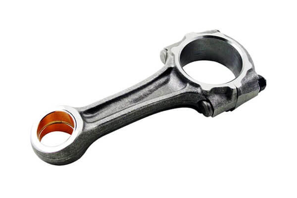
Klaņi savieno virzuli ar kloķvārpstu un pārraida mainīgos spēkus, kas rodas abpusējās kustības laikā.
Viņiem jāiztur lielas cikliskās slodzes, trieciens, saliekšana, un nogurums, vienlaikus saglabājot pietiekami vieglu svaru, lai samazinātu abpusēji kustīgo masu.
Lielākā daļa parasto klaņi tiek ražoti no kalts tērauds, lai gan alumīniju un citus specializētus sakausējumus izmanto īpašos lietojumos.
No apstrādes viedokļa, klaņi ir sarežģīti, jo to iegarenā struktūra un mainīgais šķērsgriezums nodrošina tiem salīdzinoši zemu lokālo stingrību.
Rezultātā, iespīlēšanas spēks, griešanas spēks, un atlikušais spriegums var izraisīt deformāciju, apgrūtinot precīzas urbuma ģeometrijas un centra attāluma uzturēšanu.
Tipisks savienojošo stieņu apstrādes process
Var būt vispārīgs procesa ceļš:
Kalšana → termiskā apstrāde → pamata apstrāde → neapstrādāta ārējā apstrāde → urbuma apstrāde → vāciņu atdalīšana → pusapstrāde → precīza urbšana/honēšana → galīgā pārbaude
Secība mainās atkarībā no savienojošā stieņa konstrukcijas un tā, vai tiek izmantota parastā apstrāde vai lūzumu sadalīšanas tehnoloģija.
Neapstrādāta apstrāde nodrošina stabilas atskaites virsmas un novērš lielāko daļu apstrādes pielaides.
Pēc tam tiek izmantota precīza urbšana un slīpēšana, lai sasniegtu galīgos urbuma izmērus un ģeometrisko precizitāti.
Urbuma apstrāde un apdare
Lielā un mazā gala urbumi parasti tiek apstrādāti, veicot neapstrādātu urbšanas secību, pusapdare, un precīza apdare.
Garlaicīgs nosaka precīzu izmēru un ģeometrisko formu, kamēr honing var vēl vairāk uzlabot apaļumu, cilindriskums, un virsmas īpašības, ja nepieciešams.
Lielās klases montāžai, stieņa un vāciņa attiecības ir īpaši svarīgas.
Pēc vāciņa atdalīšanas un salikšanas, gatavajam urbumam jāsaglabā projektētā ģeometrija un izlīdzinājums.
Sašķeltie savienojošie stieņi
Lūzumu sadalīšanu plaši izmanto piemērotai liela apjoma savienojošo stieņu konstrukcijām.
Tā vietā, lai starp stieni un vāciņu izveidotu parasto mehāniski apstrādātu savienojuma virsmu, kontrolēts lūzums tiek uzsākts gar iepriekš noteiktu reģionu.
Rezultātā radušās neregulārās lūzuma virsmas nodrošina ļoti individuālu pārošanās saskarni, palīdzot vāciņam un stienim atgriezties sākotnējā relatīvajā stāvoklī montāžas laikā.
Šī pieeja var piedāvāt:
- Precīza vāciņa līdz stieņa atrašanās vieta
- Samazināta relatīvā kustība
- Dažu parasto apstrādes darbību izslēgšana
- Efektīva liela apjoma ražošana
- Konsekventa montāžas pozicionēšana, ja tiek pareizi kontrolēta
Lai arī, lūzumu sadalīšanai ir nepieciešamas rūpīgi kontrolētas materiāla īpašības, iecirtuma ģeometrija, lūzumu uzvedība, un procesa parametri. Tas nav piemērots jebkuram savienojuma stieņa materiālam vai dizainam.
Savienojuma stieņu apstrādes pamatprincips
Galvenais izaicinājums ir saglabāt precīzas telpiskās attiecības starp lielā un mazā gala urbumiem, vienlaikus novēršot relatīvi tievās detaļas deformāciju..
Tas padara savienojošo stieņu apstrādi par klasisku zemas stingrības precīzas ražošanas piemēru. Iekārtas precizitāte vien nevar garantēt gala rezultātu.
Procesam vienlaikus jākontrolē atskaites punkta izvēle, armatūras ielāde, griešanas spēks, materiāla noņemšana, termiskā apstrāde, urbuma apdare, un pārbaude.
Liela apjoma automobiļu ražošanā, Tāpēc visefektīvākais process apvieno stingru un atkārtojamu stiprinājumu ar kontrolētiem apstrādes parametriem, automatizēta mērīšana, un, vajadzības gadījumā, lūzumu sadalīšanas tehnoloģija.
7. Sešu tipisku apstrādes daļu salīdzinājums
Kaut vai vārpstas, piedurknes, apvalki, pārnesumi, virzuļi, un klaņi ir ļoti dažādas ģeometrijas, to procesu plānošanas loģiku var sistemātiski salīdzināt.
| Daļas veids | Primārais apstrādes izaicinājums | Kritiskās īpašības | Kopīgi procesi | Galvenais kontroles punkts |
| Vārpsta | Rotācijas precizitāte un koncentriskums | Žurnāli, pleciem, pavedieni, atslēgas | Pagrieziens, slīpēšana, splainu apstrāde | Koaksialitāte un noplūde |
| Piedurkne | Urbuma precizitāte un deformācija | Urbums, No, gala seja | Urbšana, garlaicīgs, applūdināt, honing | Urbuma un OD attiecības |
| Mājoklis | Datu un caurumu sistēmas precizitāte | Montāžas sejas, urbumi, caurumiem | Frizēšana, garlaicīgs, urbšana, slīpēšana | Pozīcija un ģeometriskā precizitāte |
| Gear | Zobu ģeometrija un termiskās apstrādes deformācijas | Zobu profils, svins, piķis, urbt | Hobbings, veidošana, skūšanās, honing, slīpēšana | Pārnesuma precizitāte un skrējiens |
| Virzulis | Funkcionālais profils un termiskā ģeometrija | Svārki, tapas urbums, gredzenu rievas | Pagrieziens, garlaicīgs, rievu apstrāde | Profila un pozicionēšanas precizitāte |
| Klaņi | Zema stingrība un deformācija | Maza gala/liela gala urbumi | Frizēšana, garlaicīgs, honing, lūzuma sadalīšana | Urbuma izlīdzināšana un centra attālums |
Tabulā parādīts svarīgs modelis: apstrādes metodei jāatbilst detaļas funkcionālajai ģeometrijai.
Nav universāli pārāka apstrādes procesa.
Virpošana ir ideāli piemērota rotējošām virsmām, urbšana ir būtiska precīzam iekšējam diametram, frēzēšana dominē uz sarežģītām prizmatiskām virsmām, slīpēšana nodrošina augstu precizitāti pēc termiskās apstrādes, un uz formēšanas vai lūzumiem balstīti procesi var samazināt apstrādes prasības piemērotiem liela apjoma komponentiem.
8. Secinājums
Seši reprezentatīvie detaļu veidi -vārpstas, piedurknes, apvalki, pārnesumi, virzuļi, un klaņi— nodrošināt noderīgu mehāniskās apstrādes prakses šķērsgriezumu.
Neskatoties uz atšķirībām, atkal un atkal parādās tie paši pamatprincipi:
Pareiza atskaites punkta izvēle → loģiskā procesa secība → piemērotas apstrādes metodes → efektīva deformācijas kontrole → uzticama pārbaude
Tas ir īstais apstrādes procesa projektēšanas pamats.
Mērķis nav vienkārši pēc iespējas ātrāk noņemt materiālu.
Veiksmīgam apstrādes procesam ir jāpārveido sagatave par sastāvdaļu, kas atbilst tās izmēriem, ģeometrisks, funkcionāls, metalurģijas, virsmas, un ekonomiskās prasības.
Inženieriem, procesu plānotāji, un ražotājiem, šo sešu tipisko detaļu kategoriju izpratne sniedz vairāk nekā tikai apstrādes metožu sarakstu.
Tas piedāvā praktisku ietvaru nepazīstamu komponentu analīzei un procesa maršruta izvēlei, pamatojoties uz daļas struktūru, funkcionālās prasības, materiālā uzvedība, precizitāte, un ražošanas apjoms.
FAQ
Kura daļa ir visgrūtāk apstrādājama starp šiem sešiem veidiem?
Tas ir atkarīgs no precizitātes pakāpes, bet parasti zobratiem un virzuļiem ir visaugstākā procesa sarežģītība.
Zobratiem nepieciešama specializēta zobu profila apstrāde un stingras ģeometriskās pielaides, savukārt virzuļiem nepieciešama precīza sarežģītu izliektu profilu vadība un vairāku datu pārsūtīšana.
Kurš process nodrošina visaugstākās precizitātes zobrata zobu kvalitāti?
Zobu slīpēšana nodrošina visaugstāko zobu profila precizitāti un ir standarta process precīzas pakāpes rūdītiem zobratiem.
Tas var labot termiskās apstrādes radītos traucējumus un sasniegt visaugstākās AGMA vai DIN precizitātes pakāpes.
Kāpēc bāzes datu izvēle ir tik svarīga korpusa apstrādē??
Korpusiem ir vairākas savstarpēji saistītas caurumu sistēmas un savienojuma virsmas. Visas pozicionālās pielaides tiek sakrautas no primārā atskaites punkta.
Slikta atsauces punkta izvēle rada kumulatīvu izlīdzināšanas kļūdu, kas tieši pasliktina montāžas piemērotību un mašīnas veiktspēju.
Kāds labums no lūzuma sadalīšanas klaņiem?
Lūzumu sadalīšana rada perfekti saskaņotu, formas bloķēšanas saskarne starp stieni un vāciņu.
Tas uzlabo montāžas precizitāti, novērš savienojuma virsmas apstrādi, samazina detaļu skaitu, un palielina lielas klases strukturālo integritāti.
Kāda ir gultņu uzmavu urbumu standarta apdare?
Lielākā daļa precīzo gultņu urbumu tiek pabeigti ar slīpēšanu, kas rada izcilus apaļumus, kontrolēta virsmas tekstūra, un konsekvents izmērs.
Ļoti augstas precizitātes lietojumiem, var norādīt urbuma slīpēšanu vai superfinistru.