Introduzzjoni
Fi ikkastjar ta 'investiment, the quality of the ceramic shell directly determines the surface finish, eżattezza dimensjonali, and mechanical performance of the final casting.
Among all shell layers, Il kisja tal-wiċċ is the most critical because it is in direct contact with the molten metal and faithfully reproduces the geometry and surface texture of the wax pattern.
A smooth and dense shell face coat can significantly improve casting quality by reducing surface defects, minimizing machining allowances, and enhancing dimensional precision.
Bil-maqlub, excessive shell roughness may result in metal penetration, sand adhesion, pitting, and poor surface appearance, ultimately increasing production costs and rejection rates.
The roughness of the shell face coat is not controlled by a single parameter. It is the result of a complex interaction between slurry characteristics, materjali refrattarji, stuccoing processes, wax pattern quality, kundizzjonijiet ambjentali, and thermal treatments.
1. Slurry Formulation and Rheological Characteristics
The face coat slurry is the continuous matrix of the shell’s inner surface. Its composition and flow behavior are the most fundamental determinants of final surface roughness.
Every parameter change within the slurry system produces a direct, measurable effect on the cured surface topography.
Powder‑to‑Liquid Ratio and Rheological Behavior
The powder‑to‑liquid (P/L) ratio—the mass ratio of refractory powder to binder—is the most critical variable governing slurry viscosity and leveling performance.
Viscosity is inversely related to the free liquid content; as the P/L ratio increases, free liquid decreases, and viscosity rises sharply.
This relationship is highly sensitive to the solid‑liquid balance.
When the P/L ratio is too high (overly viscous slurry):
- Flowability diminishes dramatically.
- The slurry cannot effectively level out microscopic contours on the wax pattern.
- Brush marks, dipping lines, and flow ridges become “frozen” into the cured coating.
- Surface roughness increases significantly (Ra values can exceed 3.2 µm).
When the P/L ratio is too low (excessively fluid slurry):
- The coating rapidly drains from vertical surfaces.
- Insufficient coating thickness allows stucco particles to penetrate through the slurry layer, contacting the wax pattern directly.
- Gravity‑induced flow lines create uneven ripples and wavy defects.
Optimized range: For a typical silica‑sol‑zircon‑flour face coat slurry, the optimal P/L ratio lies between 3.2:1 u 3.5:1 bil-piż. Within this window:
- Viskożità (measured by a No. 4 Zahn cup) stabilizes at 35‑45 seconds.
- The slurry exhibits sufficient fluidity to fill micro‑recesses in the pattern surface.
- Thixotropic behavior prevents excessive draining.
- The wet coating achieves uniform thickness and a smooth, wiċċ ċatt.
- Final face coat roughness can be consistently maintained below Ra 1.6 µm.
Deviations from this P/L window—in either direction—invariably elevate roughness.
This makes precise P/L control one of the most important quality‑assurance activities in the investment casting foundry.
Refractory Powder Particle Size and Size Distribution
The particle size distribution of the refractory powder is the second core raw‑material factor influencing face coat roughness.
The mechanism is straightforward: if the powder consists predominantly of particles clustered around a single size, the packing density is low, leaving large interstitial voids between particles.
The resulting slurry layer is porous and rough, with numerous micro‑craters that increase surface roughness and reduce resistance to metal penetration.
Optimal particle‑size distribution requires a continuous, multi‑modal (ideally bimodal) gradation.
Fine particles fill the voids between coarse particles, achieving maximum packing density and a dense, smooth surface after curing. Experimental optimization for a zircon‑flour system shows:
| Parametru | Optimal range | Impact on roughness |
| Coarse particle fraction | 20‑30 µm | Provides structural framework. |
| Fine particle fraction | 2‑5 µm | Fills interstices; provides smoothness. |
| Fine fraction mass ratio | 30‑40% | Maximizes packing density. |
| Oversize particles (>45 µm) | <0.5% | Eliminates protrusions and localized roughness. |
With this optimized bimodal distribution, surface roughness is reduced by over 40% compared to a unimodal powder of the same average particle size.
The resulting face coat exhibits virtually no visible particle‑gap craters.
Barra minn hekk, all particles larger than 45 µm must be removed by sieving or air classification; such oversize contaminants create raised nodules on the shell surface that locally increase roughness by several times.
Binder System and Functional Additives
The binder type profoundly affects surface roughness.
The three principal binders used in investment casting—silica sol, ethyl silicate hydrolyzate, and sodium silicate—produce markedly different face coat qualities:
| Binder system | Typical surface roughness (Ra) | Vantaġġi | Limitazzjonijiet |
| Silikat tas-sodju | >6.3 µm | Spiża baxxa; fast drying. | Coarse texture; restricted to low‑precision castings. |
| Ethyl silicate | ≈3.2 µm | Good precision; spiża moderata. | Aktar għaljin; requires careful hydrolysis control. |
| Sol tas-silika | <1.6 µm | Excellent smoothness; purità għolja; colloidal particles ~10‑20 nm. | Spiża ogħla; longer drying times; sensitive to contamination. |
Silica sol is the binder of choice for high‑precision investment casting because of its extremely small colloidal particle size (typically 10‑20 nm).
This allows the formation of a dense, continuous gel film with minimal surface irregularities.
Functional additives: Small additions of surfactants and leveling agents can dramatically improve slurry wetting and leveling performance without altering the base binder chemistry:
- Surfactants (E.g., non‑ionic wetting agents at 0.1‑0.3% of total slurry mass) reduce surface tension, promoting uniform spreading and preventing pinhole or crater formation.
- Leveling agents prolong the flow time of the wet slurry film, allowing brush marks, dipping lines, and other minor application artifacts to heal before curing.
Madankollu, excessive additive use (>0.5%) can cause surface shrinkage, cratering, or pinholes.
The optimal addition range is typically 0.1‑0.5% by weight of total slurry, requiring precise metering and careful quality control.
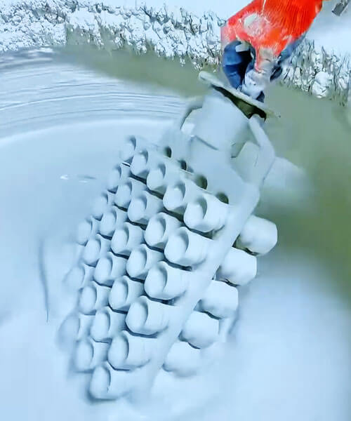
2. Stucco Process: Critical Operational Variables Governing Shell Surface Topography
The stuccoing operation is far more than simply applying refractory sand onto the wet face coat.
It is a decisive process that determines how the ceramic particles are anchored within the slurry and, konsegwentement, how the inner surface of the shell will be reproduced after drying, sparar, and metal pouring.
The embedding condition, distribution uniformity, and stability of stucco particles directly affect the microscopic contour of the shell face coat and ultimately the surface finish of the casting.

Particle Size Matching Between Stucco and Wet Face Coat
The first principle of successful stuccoing is achieving a proper relationship between the particle size of the refractory sand and the thickness of the wet face coat.
Effect of Oversized Stucco Particles
When the stucco particles are excessively coarse, their dimensions exceed the thickness of the slurry film.
Taħt dawn il-kundizzjonijiet, the particles penetrate the wet coating and directly contact the wax pattern surface.
This phenomenon produces localized impressions on the wax pattern that remain in the ceramic shell after dewaxing and firing, eventually appearing as protrusions or surface irregularities on the inner shell face.
Large stucco particles may also:
- Create local stress concentration zones;
- Cause coating thickness variations;
- Increase the probability of metal penetration defects;
- Significantly increase the shell face coat roughness.
Effect of Excessively Fine Stucco Particles
Bil-maqlub, extremely fine stucco particles tend to pack densely within the slurry layer.
The reduced inter-particle spacing decreases shell permeability and exposes the contours of numerous fine particles on the shell surface.
Bħala riżultat:
- Surface micro-protrusions become more pronounced;
- Gas permeability decreases;
- The risk of gas-related casting defects increases;
- The shell surface becomes rougher despite the smaller particle size.
Optimal Particle Size Relationship
Practical production experience has shown that the most stable embedding condition is achieved when the average stucco particle size is controlled at approximately:
50%–67% of the wet face coat thickness.
Under this condition:
- Approximately half of each particle is embedded within the slurry;
- The remaining portion stays outside the coating layer;
- Sand particles neither penetrate the wax pattern nor become fully exposed on the shell surface.
For conventional face coat thicknesses of 0.3–0.5 mm, the recommended stucco size is generally:
| Wet Face Coat Thickness | Recommended Stucco Size |
| 0.30 mm | 120–140 mesh |
| 0.40 mm | 100–120 malja |
| 0.50 mm | 80–100 mesh |
Process Timing: The Critical Stucco Application Window
The timing of stucco application is frequently underestimated in production practice, yet it has a decisive impact on particle embedding quality and surface morphology.
Premature Stucco Application
Immediately after coating, the slurry remains highly fluid and has not yet developed sufficient viscosity to support the sand particles.
Applying stucco too early can result in:
- Particle migration and displacement;
- Uneven particle distribution;
- Localized sand accumulation;
- Formation of rough bulges and waviness.
The resulting shell surface often exhibits significant roughness variations from one area to another.
Delayed Stucco Application
If stucco application is delayed excessively, partial gelation or skin formation begins on the slurry surface.
Taħt dawn il-kundizzjonijiet:
- Sand particles cannot penetrate the coating properly;
- Mechanical anchoring becomes insufficient;
- Floating particles are formed on the surface.
During subsequent shell-building operations, these loosely attached particles often detach, leaving numerous microscopic pits and cavities that substantially increase shell roughness.
Optimum Stuccoing Window
For conventional silica-sol face coat systems, the recommended stucco application period is:
30–90 seconds after coating.
Within this time interval:
- Slurry viscosity has increased to an appropriate level;
- Excessive fluidity has disappeared;
- Sufficient plasticity remains for effective particle embedding.
Konsegwentement, sand particles become uniformly distributed and firmly anchored, producing the smoothest and most consistent shell surface.
Environmental Factors Influencing Stucco Quality
The surrounding environment during stuccoing can substantially alter particle embedding behavior and shell surface quality.
Among all environmental variables, sand moisture content u ambient relative humidity are the most influential.
Moisture Content of Stucco Sand
The moisture level of stucco material should be maintained below:
0.4%
Excessive moisture introduces water into localized regions of the slurry, changing the powder-to-liquid ratio and causing abrupt increases in viscosity.
The consequences include:
- Floating sand accumulation;
- Non-uniform particle distribution;
- Weak interlayer bonding;
- Delamination defects.
Although these defects may remain hidden during shell construction, they often become evident during dewaxing and firing, where they manifest as:
- Surface pits;
- Irregular protrusions;
- Rough areas;
- Local shell spalling.
Ambient Relative Humidity
The recommended environmental humidity for stuccoing operations is:
40%–60% RH
Low Humidity Conditions
When humidity is too low:
- Surface water evaporates rapidly;
- Premature skin formation occurs;
- Sand particles cannot embed sufficiently.
The result is poor particle anchoring and increased shell roughness.
High Humidity Conditions
When humidity is excessively high:
- Drying slows considerably;
- Sand particles continue sinking under gravity;
- Some particles penetrate the slurry layer.
These conditions ultimately produce:
- Uneven shell surfaces;
- Particle settlement defects;
- Increased roughness values.
3. Pattern Surface Condition and Coating Application Technique
The face coat is formed directly on the wax pattern surface. Għalhekk, the pattern’s surface quality and the coating application method are fundamental prerequisites for achieving a low‑roughness face coat.
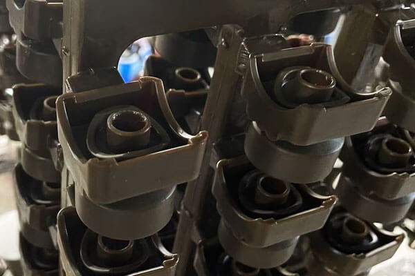
Transfer of Pattern Surface Roughness
As a foundry rule, the pattern surface roughness transfers to the shell face coat at approximately a 1:1 proporzjon.
If the wax pattern has scratches, fosos, flow lines, jew difetti oħra, even the most leveling‑optimized slurry cannot completely fill these large‑scale imperfections.
The final shell roughness will be at least as high as that of the pattern.
Requirements for low‑roughness face coats:
| Parametru | Required specification | Motivazzjoni |
| Pattern tool surface roughness | Ra ≤0.4 µm | Polished steel or aluminum tooling, not resin or plaster. |
| Wax injection parameters | Ottimizzat (pressjoni, temperatura, dwell) | Prevents flow marks, għeluq kiesaħ, and surface oxidation. |
| Post‑injection finishing | Wipe or degrease to remove mold‑release residues and micro‑burrs. | Eliminates contaminant‑induced defects. |
| Final pattern roughness | Ra ≤0.8 µm | Ensures direct transfer yields acceptable shell roughness. |
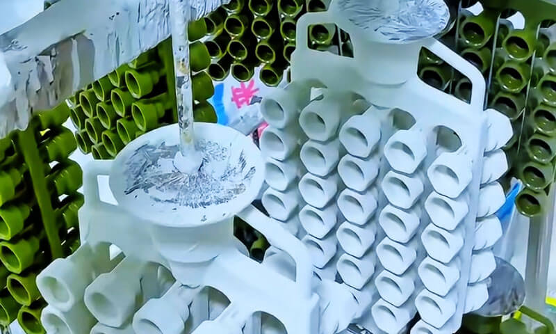
Coating Application Technique
The method of applying the face coat slurry significantly affects final surface roughness.
The three principal application techniques—brushing, tgħaddis, and pouring—produce distinct surface qualities:
| Teknika | Vantaġġi | Limitazzjonijiet | Typical roughness achieved (Ra) |
| Tfarfir | Precise control over hard‑to‑reach areas; good for complex internal cavities. | Brush marks can become frozen into the coating; operator‑dependent; bil-mod. | 1.6‑3.2 µm |
| Tgħaddis | Uniformi, even coatings; produttività għolja; minimal operator influence. | Requires sufficiently fluid slurry; pattern design must allow drainage. | <1.6 µm (l-aħjar) |
| Tferrigħ / bexx | Suitable for large or irregular patterns; good coverage. | Can produce droplets and flow lines if not carefully controlled. | 1.6‑2.5 µm |
Optimal dipping parameters:
- Pattern withdrawal speed: The most critical parameter. Withdrawal speeds in the range of 10‑15 cm/s produce a stable, uniform slurry film.
Too fast → excessive coating thickness and runs; too slow → coating is too thin and discontinuous. - Dwell time in slurry: 5‑15 seconds to allow complete wetting.
- Drainage time: After withdrawal, allow 10‑20 seconds for excess slurry to drain before stuccoing.
The dipping method, meta kkontrollati sew, achieves the lowest and most consistent roughness values.
Brushing can match dipping for small, complex parts but introduces more operator variability.
4. Post‑Application Processing: Tnixxif, Dewaxing, and Firing
Even after the face coat has been applied and stuccoed, subsequent processing steps—drying, dewaxing, and firing—can introduce or exacerbate roughness defects.
Many latent defects originating in earlier stages manifest during these thermal‑mechanical treatments.
Drying and Curing
The drying process is where the silica‑sol binder undergoes gelation. The colloidal silica particles coalesce into a continuous network, locking the refractory particles in place.
Water evaporation from the surface must be carefully controlled:
- If drying is too rapid (temperatura għolja, strong airflow): The surface dries and forms a skin while the interior remains wet.
Trapped water later evaporates, causing blisters or cracks that open up as pits on the shell surface. - If drying is too slow (low temperature, umdità għolja): The coating can sag or the stucco can settle, creating a non‑uniform texture.
Optimal drying conditions: Ħafif, uniform exposure with good air circulation but no direct impingement:
- Temperatura: 22‑25°C.
- Relative humidity: 50‑70%.
- Drying time: 4‑8 hours for a face coat, depending on slurry composition and thickness.
Dewaxing
The dewaxing step—melting out the wax pattern—must be performed with controlled heating to prevent pattern expansion from distorting the shell’s internal surface.
If the temperature rise is too rapid, the wax expands more than the ceramic shell can accommodate.
The result is internal pressure that can crack, bulge, or deform the face coat, leaving permanent surface defects on the final casting.
L-aħjar prattika: In steam dewaxing (autoclave), raise the steam pressure to 0.6 MPa ġewwa 30 sekondi.
This ensures rapid, uniform heating from the inside out. The wax melts quickly and flows out before significant thermal expansion can occur.
This technique preserves the face coat’s original smooth surface.
Isparar (Sinterizzazzjoni)
The final firing of the ceramic shell at high temperature serves to burn out residual carbon, remove volatile contaminants, and sinter the refractory particles for strength.
Firing conditions must be controlled to avoid surface degradation:
- Tisħin rapidu: Binder decomposition gases can escape too quickly, creating pinhole craters on the shell surface.
- Excessive firing temperature: Over‑sintering causes glassy phase formation and flow, creating a rippled, distorted surface.
Optimal firing schedule for silica‑sol‑zircon face coats:
- Hold temperature: 950‑1050°C.
- Hold time: 2‑3 hours.
- Ramp rate: 4‑6°C/min (gradual to allow gas escape).
F'din il-firxa, the shell obtains sufficient strength for pouring without excessive molten flow, while the face coat retains the smooth, dense texture established during earlier steps.
Roughness remains consistently low (Ra ≤1.6 µm) when properly fired.
5. Practical Quality Management and In‑Process Monitoring
Achieving consistent low roughness requires systematic monitoring and control throughout the shell‑building proċess. Recommended in‑process checks include:
| Check point | Parameter monitored | Test method | Acceptable range |
| Slurry batch | Viskożità (Zahn cup) | LE. 4 cup | 35‑45 seconds |
| Slurry batch | P/L ratio | Gravimetric | 3.2‑3.5 : 1 |
| Powder batch | Particle size distribution | Laser diffraction | Bimodal; <1% >45 µm |
| Stukk | Moisture content | Loss on drying | <0.4% |
| Ambjent | Temperatura / umdità | Hygrometer | 22‑25°C / 40‑60% RH |
| Coating operation | Dip withdrawal speed | Timer / calibrated rig | 10‑15 cm/s |
| Coating operation | Dewaxing profile | Pressure‑time recorder | 0.6 MPa in 30s |
| Isparar | Furnace profile | Thermocouple record | 950‑1050°C, 2‑3 hours |
In‑process visual inspection: Periodic inspection of stuccoed face coats using a 10× magnifier can detect early signs of stucco protrusion, clumping, or incomplete coverage.
A portable surface profilometer (contact or non‑contact) can be used on selected sacrificial patterns to verify that roughness targets are being met.
6. Translating Face Coat Roughness into Final Casting Surface Performance
The significance of shell face coat roughness extends far beyond the shell-making stage.
Fl-ikkastjar tal-investiment, the ceramic face coat serves as the negative replica of the final component surface, meaning that its micro-topography is transferred almost directly to the casting during solidification.
Konsegwentement, even minor variations in shell roughness can have a measurable impact on the functional performance, ħajja tas-servizz, and commercial value of the finished component.
For high-value precision castings, controlling face coat roughness is not merely a cosmetic requirement—it is a critical engineering parameter that influences the component’s mechanical and operational behavior.
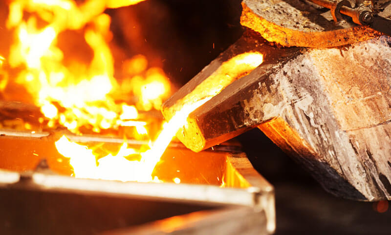
Surface Replication Mechanism
Waqt it-tferrigħ, molten metal fills every microscopic depression and protrusion on the ceramic shell surface.
Wara s-solidifikazzjoni, the casting reproduces these surface features with remarkable fidelity.
Although factors such as:
- Alloy shrinkage,
- Metal fluidity,
- Mold-metal reactions,
- Ramel burn-on,
can slightly modify the final surface texture, the shell face coat remains the dominant factor governing casting roughness.
In most precision investment casting processes, the roughness transfer ratio between the shell and the casting ranges from:
1:1 to 1:1.3
This means that a shell face coat with an Ra value of 1.6 μm typically produces a casting surface roughness of approximately 1.8–2.0 μm.
Impact on Mechanical Performance
Reżistenza għall-għeja
Surface irregularities act as microscopic notches and stress raisers. Under cyclic loading, these regions become preferred locations for crack initiation.
A smoother casting surface offers:
- Lower stress concentration factors;
- Reduced crack nucleation sites;
- Longer fatigue life;
- Improved reliability under dynamic loading.
Dan huwa partikolarment importanti għal:
- Xfafar tat-turbina;
- Komponenti strutturali tal-inġenji tal-ajru;
- Partijiet tal-magni tal-karozzi;
- High-speed rotating equipment.
Studies have shown that reducing surface roughness from Ra 4.0 μm to Ra 2.0 μm can improve fatigue life by more than 20% in certain high-strength alloys.
Reżistenza għall-korrużjoni
Surface morphology strongly influences corrosion behavior.
Rough surfaces contain:
- Valleys and crevices;
- Areas of stagnant electrolyte;
- Micro-galvanic cells.
These features accelerate:
- Korrużjoni tal-pitting;
- Korrużjoni tal-qsim;
- Stress-korrużjoni qsim.
For stainless steel medical implants and chemical-processing components, a smooth casting surface significantly improves long-term corrosion resistance and biocompatibility.
Wear Performance
The initial surface condition directly affects friction and wear mechanisms.
A rough surface generally leads to:
- Higher friction coefficients;
- Increased abrasive wear;
- Faster material removal;
- Greater heat generation.
Komponenti bħal:
- Impellers tal-pompa;
- Korpi tal-valvi;
- Hydraulic components;
- Sliding mechanical parts,
benefit substantially from lower surface roughness.
Influence on Fluid Dynamic Efficiency
In flow-handling equipment, surface roughness directly affects fluid behavior.
Microscopic surface protrusions disturb the boundary layer and increase turbulence, li jwassal għal:
- Higher friction losses;
- Reduced flow efficiency;
- Żieda fil-konsum tal-enerġija;
- Greater pressure drop.
This phenomenon is particularly significant in:
- Xfafar tat-turbina;
- Komponenti tal-kompressur;
- Impellers tal-pompa;
- Aerospace flow channels.
For precision turbine applications, even a small reduction in surface roughness can improve aerodynamic efficiency and reduce operating costs over the service life of the equipment.
Influence on Coating and Surface Treatment
Many investment castings require secondary operations such as:
- Elettroplating;
- Anodizzazzjoni;
- Kisi PVD;
- Bexx termali;
- Pittura.
Excessive surface roughness may cause:
- Non-uniform coating thickness;
- Poor coating adhesion;
- Localized defects;
- Increased finishing costs.
By producing castings with superior as-cast surfaces, manufacturers can significantly reduce the amount of polishing and machining required before surface treatment.
Dimensional Accuracy and Machining Allowance
Surface roughness also influences dimensional control.
A rough casting surface typically requires:
- Greater machining allowance;
- Additional grinding operations;
- More extensive finishing procedures.
This increases:
- Spiża tal-manifattura;
- Ħin taċ-ċiklu tal-produzzjoni;
- Material waste.
Bil-maqlub, low-roughness castings can often be used in near-net-shape applications, maximizing the economic advantages of investment casting.
Aesthetic and Commercial Value
For products where appearance is important, surface finish becomes a critical quality indicator.
Eżempji jinkludu:
- Impjanti mediċi;
- Consumer electronics components;
- Luxury hardware;
- Decorative metal products;
- Premium automotive parts.
A smoother surface provides:
- Better visual appearance;
- Enhanced perceived quality;
- Improved customer satisfaction;
- Higher product value.
F'ħafna każijiet, the surface finish of the casting directly determines market acceptance.
Correlation Between Face Coat Roughness and Casting Surface Quality
Extensive industrial experience and experimental investigations have established a clear relationship between shell roughness and casting surface finish.
| Face Coat Roughness (Ra, μm) | Typical Casting Roughness (Ra, μm) | Applikazzjonijiet tipiċi |
| ≤ 1.6 | ≤ 2.0 | Komponenti aerospazjali, Impjanti mediċi, Xfafar tat-turbina, partijiet tal-karozzi high-end |
| 1.6–3.2 | 2.0–4.0 | Valvoli industrijali, pompi, precision machinery, komponenti idrawliċi |
| > 3.2 | > 4.0 | Construction equipment, makkinarju tqil, general engineering castings |
7. Konklużjoni
The surface roughness of investment casting shell face coats is controlled by a full-process multi-factor coupling mechanism, covering slurry material design, stucco operation specifications, wax pattern pretreatment, coating techniques, and post-treatment thermochemical processes.
Investing in control at each of these points yields a compounding benefit: each optimized step contributes to a final surface quality that may be an order of magnitude finer than a shell produced without such control.
For foundries striving to meet the demands of precision engineering—aerospace, mediku, high‑performance automotive—the pursuit of low face‑coat roughness is not an optional quality program; it is a strategic competitive imperative.