
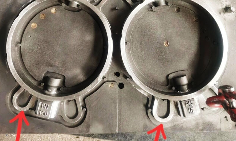
I have been producing shell mold cast steel valves for a long time, and I can tell you that the defect location usually tells you the answer before you even open the mold.
When the porosity appears at the lug-to-body transition, or at the root of a flange, it is almost never a random gas problem.
It is a trapped gas pocket—a location where the metal arrives, closes the corner, and seals the gas inside.
This article is a case analysis of exactly that defect. The part is a WCB cast steel valve produced by the shell mold process, poured at 1620°C.
The defect appears at the corner where the lug meets the valve body—a classic corner gas pocket and gas entrainment location, and one of the highest-risk dead zones in cast steel valves.
1. The Defect and the Mechanism
daļa: WCB cast steel vārsts, shell mold process.
Izliešanas temperatūra: 1620° C.
Defect location: the transition corner between the lifting lug and the valve body, and the flange root.
Defekta veids: trapped gas pocket / gas entrainment at a corner dead zone.
The mechanism is straightforward once you picture the flow.
Liquid steel flows toward the corner. The shell sand heats rapidly and begins to generate gas.
If that gas cannot escape through the mold venting path before the steel arrives and seals the corner, it is trapped.
The steel closes the corner, the gas remains at the interface, and the result is a subsurface or surface porosity exactly at the transition.
WCB is poured at high temperature. That high temperature accelerates the decomposition of the phenolic resin in the shell sand, and the gas generation rate is higher than in cast iron.
Cast steel is therefore more prone to trapped gas bursts than iron castings of the same geometry.
The key insight is this: the corner is not just a geometric feature. It is a venting dead zone. The gas has nowhere to go, and the metal gets there first.
2. Cause Module One: Venting Design (The Primary Suspect)
For the WCB valve shown in this case, venting design is the first cause I would investigate.
The gas porosity is concentrated at the lug-to-body transition, which suggests that the local cavity may not have an effective gas escape path during filling.
No Dedicated Vent at the Lug Corner
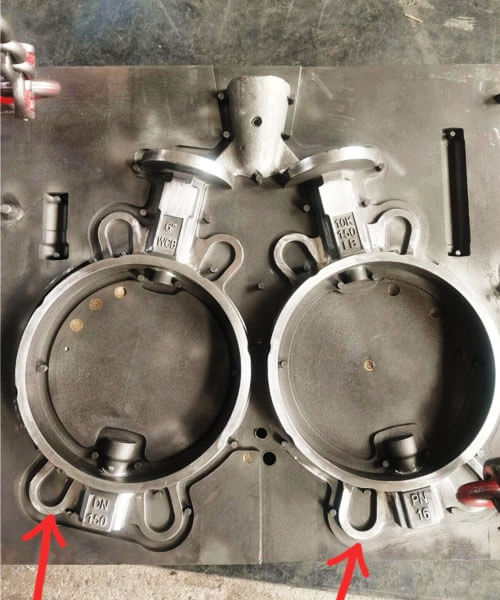
As shown in the drawing, the red-marked lug transition forms a local geometric dead zone. There is no dedicated vent plug or vent groove directly connected to this area.
Although several circular vent plugs are installed on the large flange face, the lug root itself has no supplementary venting.
When molten steel reaches this corner, it can seal the local cavity before the gas generated by the resin-coated sand has escaped.
This is a common mistake in valve mold design: venting is often arranged according to tooling convenience rather than the actual locations where gas accumulates.
The solution is to identify the local gas-trapping zones and provide effective venting paths at those positions.
Vent Quantity and Position Do Not Match the Filling Pattern
The existing vent plugs are concentrated on the bottom face of the large flange, with no additional venting at the lug transition or other potential gas-accumulation points.
Lai arī, venting effectiveness depends not only on the number of vents but also on their positions relative to the molten steel’s filling sequence.
If the steel reaches the lug root before the accumulated gas can escape, vents located elsewhere on the mold may provide little benefit.
Tāpēc, vent placement should be based on two factors:
- Gas accumulation locations: Corners, cilpas, priekšniekiem, and other geometric dead zones.
- Filling sequence: Areas where gas must remain connected to an escape path until the molten steel approaches.
Venting that does not account for the filling pattern is unlikely to solve localized gas porosity reliably.
Vent Cross-Section Is Too Small or the Vent Path Is Interrupted
Even when vent plugs or grooves are provided, their actual discharge capacity must be checked.
If the vent cross-section is too small, it may not discharge gas quickly enough to handle the volume generated by the heated shell.
Līdzīgi, a vent groove that stops partway along its path can create a dead-end passage rather than an effective outlet.
Kopējās problēmas ietver:
- Insufficient vent groove width or depth;
- Interrupted vent passages;
- Sand or shell residue blocking the outlet;
- Poor connection between the cavity and the parting line;
- Excessive resistance along the venting path.
A properly designed vent must provide a continuous and unobstructed passage from the gas-accumulation area to the outside of the mold.
For this valve, I would first inspect the lug-root transition, verify the existing flange vents, and then determine whether an additional local vent plug or vent groove is required.
3. Cause Module Two: Gating System and Fill Sequence
Venting is necessary, but it is not sufficient. If the fill sequence seals the vent before the gas can escape, even a well-vented mold will trap gas.
Fill Sequence Seals the Lug Vent Path First
With the current gating layout, the steel flow front reaches the lug root before the rest of the cavity is filled.
The corner is sealed early, and the gas generated afterward by shell decomposition is trapped with no route out.
This is the critical point. The vent must be open at the moment the gas is generated, not just present in the mold. If the steel arrives at the vent location first, the vent is functionally closed.
Ingate Location and Flow Velocity
If the ingate directs the steel straight at the lug, or if the steel runs along the wall and wraps around the lug at high speed, gas entrainment occurs.
The flow curls into the corner, and the gas is folded into the metal rather than pushed out ahead of it.
The difference between a smooth, progressive fill and a wrapping, curling fill is often the difference between a sound lug and a porous one.
4. Cause Module Three: Shell Sand Factors
In the shell mold process, resin-coated sand is the primary source of gas generated during pouring.
The amount of gas produced and the rate at which it is released directly affect the load on the mold’s venting system.
If gas generation exceeds the local venting capacity, gas entrapment becomes more likely, particularly at geometric dead zones such as the lug-to-body transition.
Excessive Gas Generation from Shell Sand
Excessive gas generation can result from an unsuitable sand formulation or unstable material control.
- Excessive resin content: Too much phenolic resin increases the amount of gas released during thermal decomposition when molten steel enters the mold.
- Unstable reclaimed sand ratio: Changes in the proportion of new and reclaimed sand can affect the shell’s resin content, gas evolution, and overall thermal behavior.
- High instantaneous gas release: At the pouring temperature of approximately 1620°C, resin decomposes rapidly. If gas is released faster than it can escape, the local venting system may become overloaded.
These factors do not necessarily cause porosity throughout the entire casting.
When venting is marginal at a specific location, such as the lug root, excessive gas generation can make an existing local gas-trapping problem more severe.
Insufficient or Excessive Shell Curing
Shell curing must be properly controlled. Both insufficient and excessive curing can contribute to gas-related defects, although through different mechanisms.
- Insufficient curing: An inadequately cured shell may undergo more intense thermal decomposition during pouring, releasing a large volume of gas and increasing the risk of gas accumulation in the mold cavity.
- Excessive curing: Over-curing can make the shell brittle and increase the risk of sand shedding. It may also reduce the effectiveness of the shell’s microporous structure, restricting gas permeability.
The key issue is the balance between shell strength and gas permeability. A shell must be sufficiently cured to maintain its integrity during handling and pouring, but its structure must also retain adequate permeability for gas discharge.
At the lug corner, where the venting path may already be limited, either condition can increase the likelihood of gas entrapment.
Uneven Shell Thickness at the Lug Corner
The lug-to-body transition is a geometrically complex area where shell sand can accumulate during mold preparation. Rezultātā, the local shell thickness may be greater or less than that of the surrounding regions.
Uneven shell thickness affects both the amount of resin available for gas generation and the local thermal response during pouring.
A thicker section may contain more resin-coated sand and therefore release more gas when heated.
Variations in shell thickness can also produce differences in heating and gas-release behavior, making local venting conditions less predictable.
Šī iemesla dēļ, shell thickness should be kept reasonably uniform around the lug root and other complex transitions. Avoid unnecessary sand buildup while ensuring that the shell retains sufficient strength.
For this WCB valve, the shell sand system should be checked for resin content, new-to-reclaimed sand ratio, curing consistency, and local thickness variation.
Lai arī, these factors should be evaluated alongside the venting design: excessive gas generation can aggravate the defect, but it does not by itself explain why porosity is concentrated at the lug-to-body transition.
5. Cause Module Four: Pouring Parameters
The WCB valve is poured at approximately 1620° C, which is within the normal pouring temperature range for WCB cast steel. Lai arī, liešanas ātrums, stream stability, and turbulence still need to be checked.
Pouring Speed Too Fast
Excessive pouring speed can cause molten steel to reach the lug-to-body transition too quickly, sealing the local gas escape path before the gas has been fully discharged.
Once the corner is enclosed by molten steel, the remaining gas becomes trapped and forms localized gas porosity.
In cast steel production, gas defects are not necessarily caused by insufficient pouring temperature. Excessive filling speed and premature closure of venting paths can be equally important causes.
Interrupted or Turbulent Pouring
An interrupted metal stream or turbulent pouring operation can introduce air into the molten steel and disturb the filling pattern. This type of defect is more likely to produce dispersed gas porosity rather than a single, localized gas pocket at the lug root.
Maintaining a continuous, stable pouring stream is therefore essential for reducing air entrainment and achieving consistent mold filling.
A Note on Pouring Temperature
Higher pouring temperatures accelerate the thermal decomposition of the phenolic resin in the shell mold, potentially increasing the instantaneous gas-generation rate. If the venting capacity is insufficient, this can aggravate gas entrapment.
Lai arī, 1620°C is a normal pouring temperature for WCB, so temperature should not be the first parameter adjusted in this case.
Prioritize local venting and filling sequence, then evaluate pouring speed and process stability. Only consider temperature adjustments after these factors have been checked.
The principle is to correct gas evacuation first and adjust pouring temperature last.
6. Cause Module Five: Corner Geometry
The transition between the lug and the valve body is a right-angle transition. Sharp corners are the most effective gas traps in any casting.
The problem is aerodynamic, not just geometric. At a sharp corner, the gas flow forms a vortex. The gas circulates in the corner and stays there instead of moving toward the vent.
A larger radius allows the gas to flow smoothly toward the vent path rather than being trapped in a circulating pocket.
If the tooling can be modified, increasing the transition radius is one of the most reliable long-term fixes.
7. Corrective Action Sequence: What Should Be Changed First?
For the WCB valve shown in this case, corrective actions should follow a low-cost-first approach, starting with the measures most likely to eliminate localized gas porosity and progressing to more extensive process or tooling modifications.
Prioritāte 1: Improve Local Venting
This is the first and most effective measure to investigate.
Add a vent plug at the lug root.
Install a small vent plug at the highest point or last-to-fill dead zone of the lug-to-body transition. Alternatīvi, cut a 0.2–0.3 mm thin vent groove from the corner to the parting line.
The objective is to provide a direct escape path for accumulated gas before the molten steel seals the corner.
Check existing flange-face vents.
Inspect and clean the existing vent plugs to ensure they are not blocked by sand or shell residue. A blocked vent cannot provide effective gas discharge, regardless of its original design.
Prioritāte 2: Optimize the Filling Sequence
The next step is to prevent molten steel from closing the lug vent prematurely.
Adjust the ingate position.
Modify the ingate location or metal flow direction so that the lug region is filled later, allowing more time for gas to escape through the venting path.
Control pouring speed.
Reduce excessive pouring speed and maintain smooth, stable filling to minimize turbulence and gas entrainment. Avoid aggressive pouring.
Prioritāte 3: Optimize the Casting Geometry
If tooling or product design modifications are possible, increase the transition radius (R) at the lug-to-body junction.
A larger fillet reduces the sharp internal corner, improves local metal-flow conditions, and minimizes the possibility of gas accumulation in the transition area.
Prioritāte 4: Control the Shell Sand Formulation
If venting and filling adjustments are insufficient, review the resin-coated sand system.
- Control resin content: Appropriately reduce resin addition if gas generation is excessive.
Maintain a consistent ratio of new sand to reclaimed sand, avoiding uncontrolled changes in sand sources. - Stabilize shell curing: Maintain consistent curing conditions to ensure adequate shell strength while controlling gas generation.
Prioritāte 5: Adjust Pouring Temperature as a Last Resort
If testing confirms that excessive instantaneous gas generation is contributing to the defect, a controlled trial of reducing the pouring temperature by approximately 20° C, from 1620°C to 1600°C, can be considered.
Lai arī, avoid excessive temperature reduction, as it may introduce cold shuts or incomplete filling.
For this WCB valve, the recommended sequence is: local venting → filling sequence → casting geometry → shell sand formulation → pouring temperature.
Prioritize the venting modification before making more extensive process changes.
8. Distinguishing the Two Types of Porosity
Correctly identifying the type of porosity is essential because trapped cavity gas and shell sand-related gas porosity have different causes and require different corrective actions.
Trapped Cavity Gas (Most Likely in This Case)
Raksturīgās īpašības ietver:
- Concentrated at a specific geometric location, such as a lug root, stūrī, or flange transition.
- Appears as single or localized gas porosity rather than defects distributed throughout the casting.
- Shows noticeable improvement after adding or improving local venting.
This type is primarily associated with inadequate local venting or premature closure of the gas escape path during filling. The first corrective measures should focus on venting design and filling sequence.
Shell Sand-Related Subsurface Porosity
Raksturīgās īpašības ietver:
- Gas porosity scattered across multiple areas of the casting.
- Defects appearing on both surface and subsurface regions.
- A strong relationship with excessive resin gas generation or unstable shell sand conditions.
This type requires investigation and adjustment of the shell sand formulation, particularly resin content and gas generation, rather than relying solely on additional local vents.
The practical distinction is straightforward: if porosity repeatedly appears at one geometric dead zone, investigate trapped cavity gas first. If defects are distributed across the casting, investigate the shell sand system.
For the WCB valve in this case, the localized porosity at the lug-to-body transition points more strongly toward a local venting and filling-sequence problem.
9. Final Takeaway for Shell Mold Cast Steel Valve Production
The WCB cast steel valve shown in this case is a typical example of why localized gas porosity should be diagnosed from the defect location and filling behavior rather than from pouring temperature alone.
At approximately 1620° C, the molten steel places a substantial thermal load on the resin-coated shell. The shell generates gas rapidly.
If the lug-to-body transition does not have an effective escape path, the advancing steel can seal the corner and trap the gas.
The most likely process chain is:
Resin-coated sand generates gas → local venting is insufficient → molten steel reaches the lug transition → the escape path is closed → gas becomes trapped → localized gas porosity forms.
For this type of WCB valve defect, the practical correction sequence is:
- Add or improve local venting at the lug-to-body transition.
- Check whether existing vents are actually open and effective.
- Review the gating system and filling sequence.
- Reduce excessive filling velocity and turbulence.
- Stabilize the shell sand and resin system if gas defects are widespread.
- Improve sharp geometric transitions where the design permits.
- Adjust pouring temperature only after the primary causes have been investigated.
The most important rule is straightforward:
Localized gas porosity requires a localized process diagnosis.
Par shell mold cast steel valves, the three locations that deserve particular attention are cilpas, priekšniekiem, and flange-to-body transitions.
When these areas repeatedly produce gas defects, the first question should not be “Is the pouring temperature wrong?” but rather:
“Where is the gas supposed to escape, and what causes the molten steel to close that path?”
That question usually leads much faster to the real cause and the correct corrective action.

