
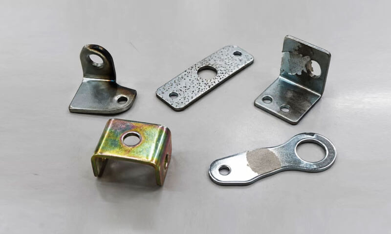
After many years on the galvanizacija line, Naučio sam jednu stvar: greška u oplati rijetko je problem jednog parametra.
Peeling is not just “bad adhesion.” Pitting is not just “dirty bath.” Burning is not just “too much current.” Color variation is not just “bad passivation.”
Each defect is the visible end of a process chain. If you chase the defect without tracing the chain, you will fix it for a week and see it again next month.
That is why the most important question in plating troubleshooting is not “What is the defect?” but “Where in the process did the chain break? ”
This article covers the five defects I see most often: piling, zadirkivanje, gori, bare spots, and color variations.
For each one, I will describe the appearance, the root causes, the troubleshooting sequence, and the fixes. I will also explain why the same defect keeps coming back—and how to stop it.
1. Piling
Peeling occurs when the deposited metal coating fails to bond adequately to the substrate or to an underlying coating layer.
Typical signs include localized blisters, lifted edges, ljušteći se, or large areas of coating detaching after bending, utjecaj, or handling.
U proizvodnji, peeling is often a pretreatment problem rather than a plating-time problem. If oil, oksid, hrđa, or other contaminants remain on the surface, the deposited metal cannot form a reliable bond.
A coating may initially look acceptable but later separate during machining, skupština, thermal exposure, ili uslugu.

Common Causes of Electroplating Peeling
| Glavni uzrok | Mehanizam | Typical Signs |
| Incomplete odmašćivanje | Oil and grease prevent intimate contact between the substrate and deposited metal | Localized peeling, often in contaminated areas |
| Inadequate kiselina kiseli ili activation | Oksidi, hrđa, or scale remain on the surface | Poor adhesion across affected areas |
| Cross-contamination tijekom ispiranje | Residual chemicals or contaminants are transferred between process tanks | Irregular adhesion failures |
| Excessive delay nakon activation | The activated surface reoxidizes or becomes contaminated before plating | Peeling despite apparently acceptable cleaning |
| Oxidized ili unsuitable supstrat | The base material has an unstable surface condition or is incompatible with the process | Repeated adhesion failures on particular materials or batches |
| Siromašan interlayer prianjanje | The interface between successive deposited layers is weak | Separation between coating layers rather than at the substrate |
How to Troubleshoot Peeling
Korak 1: Verify degreasing effectiveness.
Check cleaner concentration, temperatura, vrijeme liječenja, and contamination level.
A water-break test can help identify residual oil on suitable substrates, although it does not replace a validated cleanliness test.
Korak 2: Inspect the pickling and activation process.
Confirm that the selected chemistry removes the relevant oxide or scale without excessively attacking the base metal.
Over-pickling can also cause problems, including roughening, smut formation, or hydrogen-related risks in susceptible materials.
Korak 3: Check rinsing between process stages.
Poor rinsing can carry cleaner, kiselina, soli, or dissolved metals into subsequent tanks. Inspect rinse-water quality, overflow, uznemirenost, and drag-out control.
Korak 4: Reduce unnecessary delays before plating.
Establish a controlled maximum transfer time between activation and plating. Keep activated surfaces protected from drying, kontaminacija, i oksidaciju.
Korak 5: Determine the actual failure interface.
Examine the peeled surface and, gdje je potrebno, use microscopy or cross-sectional analysis to establish whether separation occurred at the substrate/coating interface or between coating layers.
Engineer’s Note
I always start with degreasing and rinsing. Nine times out of ten, peeling is a cleaning problem, not a plating problem. If the water-break test fails before plating, stop—do not put the part in the bath.
2. Zadirkivanje
Pitting is characterized by small, crater-like depressions in the plated surface.
The pits may resemble pinholes, and a high density of defects can make the coating appear rough or porous.
The important distinction is that pitting is a recessed defect, not a raised particle. Raised nodules or rough deposits may point toward particulate contamination, dendritic growth, or other deposition problems.
Međutim, trapped particles can also create pits, so visual inspection should be combined with further examination.
Pitting can originate in the substrate, during pretreatment, or within the plating bath itself.
Gas bubbles adhering to the workpiece are another common cause, especially when the part geometry or rack orientation allows bubbles to remain trapped.

Main Causes of Electroplating Pitting
| Uzrok | How It Produces Pits | Što provjeriti |
| Existing supstrat mane | Poroznost lijevanja, corrosion pits, ogrebotine, or dents remain visible after plating | Incoming surface quality and pre-plating inspection |
| Inadequate čišćenje | Residual oil, produkti korozije, or other contamination interferes with uniform deposition | Odmašćivanje, kiseli, activation, and rinsing |
| Particulate kontaminacija | Solid particles become embedded in the coating or disturb local deposition | Bath filtration, filter elements, circulation, and tank cleanliness |
Gas bubbles adhering to the surface |
Areas covered by bubbles receive insufficient metal deposition | Part orientation, uznemirenost, vlaženje, and gas release |
| Unbalanced bath kemija | Chemistry outside the operating window may promote rough or irregular deposits | Bath analysis and process records |
| Excessive lokalni trenutni gustoća | Unstable deposition can contribute to roughness or related surface defects | Current density, geometrija, and electrical distribution |
A Practical Method for Diagnosing Pitting
An experienced finishing engineer does not immediately assume that every pit originates in the plating bath.
The first step is to establish whether the defect existed before plating.
- Inspect the substrate before processing. Review incoming parts and pretreatment samples to determine whether the pits are already present.
- Examine stripped parts where appropriate. If the coating can be removed safely using a validated stripping process, inspect the exposed substrate for residual pits.
Stripping itself can attack or alter the substrate, so the method must be suitable for the material. - Check the filtration system. Inspect filter elements, circulation flow, pump condition, tank deposits, and potential sources of particulate contamination.
- Review the defect distribution. Determine whether pits are random, concentrated in recessed areas, associated with particular orientations, or limited to certain batches.
- Evaluate bubble release. Check rack orientation, part drainage, solution movement, and whether recessed features can trap air or hydrogen bubbles.
How to Prevent Pitting
- Improve incoming material inspection and surface preparation.
- Maintain filtration and circulation according to the bath supplier’s requirements.
- Remove sludge and accumulated deposits through controlled tank maintenance.
- Use appropriate wetting agents or other approved bath additives when required by the process.
- Optimize rack orientation and agitation to prevent persistent bubble attachment.
- Monitor bath chemistry and operating conditions within the specified control limits.
Za lijevane komponente, particular attention should be paid to casting porosity and surface-connected voids. Electroplating follows the underlying surface rather than reliably eliminating its defects.
If the substrate contains open pores or deep corrosion pits, poliranje, obrada, impregnation where appropriate, or another validated pretreatment may be necessary before plating.
Engineering tip:
A defect map is often more valuable than a general visual judgment. Record the location, gustoća, and distribution of pits across representative parts.
A repeatable pattern can help distinguish substrate porosity from trapped bubbles or bath contamination.
3. Gori
Burning is a plating defect that commonly appears at edges, oštri kutovi, protrusions, and other areas where the local current density becomes excessively high.
The affected deposit may look dark, siva, hrapav, praškast, or poorly consolidated. U teškim slučajevima, the coating may be brittle or loosely attached.
The underlying mechanism is usually excessive local current density relative to the bath’s ability to deposit sound metal.
Although the overall current setting may be within the normal operating range, the actual current is not distributed evenly over a component’s surface.
Sharp corners and protruding features tend to concentrate the electric field.
If these areas receive too much current, the local deposition rate can exceed the practical operating window of the electrolyte, producing a rough or burned deposit.

Common Causes of Burning
| Glavni uzrok | Why It Happens | Typical Corrective Action |
| Excessive trenutni gustoća | Current exceeds the bath’s stable deposition range | Reduce current density and verify the effective plated area |
| Siromašan stalak orijentacija | Sharp features face the anode directly and receive concentrated current | Reorient the part or change rack positioning |
| Nedovoljno anoda distance | Certain areas receive disproportionately high current | Adjust anode-to-workpiece spacing where practical |
| Unbalanced anoda arrangement | Electric-field distribution is concentrated around protruding features | Reposition or redesign the anode arrangement |
Inadequate shielding |
High-current areas are not protected from excessive current | Use shields, pregrade, or auxiliary electrodes as appropriate |
| Bath kemija outside specifikacija | Low metal concentration, unsuitable additive levels, or other chemistry deviations narrow the operating window | Analyze and restore the bath to its specified operating range |
| Siromašan uznemirenost ili masa prijenos | Local transport conditions are insufficient for the applied current | Optimize agitation and solution movement |
How to Troubleshoot Burning
1. Verify current density rather than current alone.
Calculate current density using the actual effective plated area and the process’s established calculation method.
Check whether complex geometry has caused local current concentration even when the total current appears normal.
2. Inspect rack orientation.
Determine whether the burned areas face the anode directly or protrude toward it. A small change in orientation can sometimes improve the current distribution significantly.
3. Review anode placement and spacing.
Compare the distance between the anode and different regions of the workpiece. Check whether the anode arrangement creates a high-current zone near corners or raised features.
4. Evaluate shielding and auxiliary electrodes.
Shields, insulating baffles, thieves, and auxiliary anodes or cathodes may be used to redistribute current, ovisno o procesu.
The correct solution depends on whether the objective is to reduce excessive deposition or improve current delivery to recessed areas.
5. Check the bath’s operating window.
Confirm metal concentration, pH where applicable, temperatura, additive condition, uznemirenost, and other chemistry-specific parameters against the supplier’s specifications.
Engineer’s Note
Burning at edges is predictable. If you see it, do not just lower the current—check the rack.
A part hanging with a sharp edge facing the anode will burn even at “normal” current. Sometimes the fix is a simple reorientation, not a bath change.
4. Bare Spots
Bare spots are areas where the required metal coating has not formed, leaving the substrate exposed or covered by a visibly different surface.
They may appear as isolated unplated patches, irregular areas with a different color or gloss, or thinly coated regions that fail to meet specification.
U proizvodnji, bare spots generally require investigation in two directions: whether sufficient current reached the area and whether the surface was chemically ready to receive the deposit.
A part may have excellent electrical contact but still fail to plate where residual oil or oxide prevents deposition.
Obrnuto, a perfectly clean surface may remain unplated if the rack connection is unstable or the geometry prevents adequate current delivery.

Common Causes of Bare Spots
| Uzrok | Mehanizam | Inspection Focus |
| Siromašan stalak kontakt | High contact resistance or an unstable connection restricts current | Contact points, stezaljke, hooks, and rack cleanliness |
| Interrupted električni path | Current does not flow reliably through the component | Rectifier output, kabeli, rack connections, and electrical continuity |
| Residual ulje ili mast | Contamination prevents proper wetting and deposition | Degreasing and surface-cleanliness verification |
| Oksidi ili korozija proizvodi | The substrate is not sufficiently activated | Kiseli, activation, and pre-plating surface condition |
Localized contamination |
Affected areas repel the solution or inhibit deposition | Handling practices, rukavice, transfer equipment, and rinse quality |
| Duboko udubljenja ili shielded geometrija | Local current density is too low to deposit the required thickness | Geometrija dijela, rack design, and current distribution |
| Inadequate prethodna obrada pokrivenost | Certain surfaces receive insufficient cleaning or activation | Spray coverage, immersion, uznemirenost, and drainage |
Troubleshooting Bare Spots Step by Step
Korak 1: Check rack contacts.
Look for loose connections, oxidized contact surfaces, worn clamps, and contact points with insufficient pressure.
Confirm that the contact area remains adequate throughout the plating cycle.
Korak 2: Verify electrical continuity.
Inspect cables, sabirnice, rectifier connections, and rack components. Review current and voltage records for interruptions or unusual fluctuations.
Korak 3: Examine the exposed substrate.
Determine whether the surface is oily, oksidirano, corroded, or otherwise contaminated. Compare the affected area with a properly plated region.
Korak 4: Investigate local geometry.
Deep holes, narrow grooves, recessed faces, and shielded regions may experience low current density. Assess whether rack positioning or electrode placement is limiting deposition.
Korak 5: Review the pretreatment sequence.
Confirm that the relevant areas are properly degreased, rinsed, activated, and transferred to the plating tank without unacceptable delays.
Engineering tip:
Bare spots that occur randomly across an entire rack suggest a different problem from bare spots that always appear inside the same recess.
Random defects often justify checking contact stability and contamination; repeatable geometric defects call for closer examination of current distribution and solution access.
5. Color Variations
Color variation occurs when plated components display inconsistent shades, svjetlina, sjaj, or overall appearance.
Typical examples include parts from the same batch appearing darker or lighter, different areas of one component showing different colors, or successive production batches having noticeably different tones.
Color variation is especially important for decorative plating, vidljiv hardver, proizvodi široke potrošnje, and components with strict appearance requirements.
Međutim, not every color difference indicates a coating failure. The significance depends on the plating system, the required finish, and whether the coating meets its functional specifications.
Na primjer, zinc-plated parts with a passivation or conversion coating may show color differences caused by variations in the post-treatment process.
Nickel or chromium systems may display different gloss levels because of substrate preparation, deposit thickness, or surface roughness.
The correct diagnostic approach is to evaluate the entire finishing sequence rather than changing bath chemistry immediately.

Main Causes of Electroplating Color Variation
| Faktor | How It Affects Appearance | Što provjeriti |
| Uneven premazivanje debljina | Different deposit thicknesses can change brightness, pokrivenost, or optical appearance | Thickness measurements at multiple locations |
| Different stalak pozicije | Parts receive different current distributions because of anode distance and geometry | Rack layout and position-specific trends |
| Inconsistent pasivacija uvjeti | Vrijeme, temperatura, koncentracija, or bath condition changes the final conversion coating | Passivation records and bath analysis |
| Inadequate ispiranje | Residual chemicals or contamination alter the surface or interfere with subsequent treatment | Rinse-water quality, protok, and carryover |
Uneven drying |
Residual water, drainage patterns, or inconsistent drying can leave stains or alter appearance | Drying temperature, vrijeme, protok zraka, and part orientation |
| Plating-bath varijacija | Changes in metal concentration, pH, aditiva, kontaminacija, or operating conditions alter deposit characteristics | Bath analysis, replenishment records, and maintenance history |
| Substrate varijacija | Differences in alloy, hrapavost površine, poliranje, or casting condition affect the final appearance | Incoming material and pretreatment consistency |
| Viewing i mjerenje uvjeti | Rasvjeta, viewing angle, and surface reflectivity influence perceived color | Inspection lighting and measurement procedure |
How to Investigate Color Differences
1. Measure coating thickness.
Compare thickness at representative locations on the same component and across different rack positions.
Use an appropriate method for the coating/substrate combination, such as X-ray fluorescence (XRF) or another validated thickness-measurement technique.
2. Review rack position and orientation.
Determine whether darker, upaljač, glossier, or duller parts correspond to particular positions in the rack.
Consistent position-related variation may indicate differences in current distribution or solution flow.
3. Check passivation or conversion coating conditions.
For systems that use passivation, pretvorbeni premazi, or other post-treatments, verify treatment time, temperatura, kemija, ispiranje, i uvjetima sušenja.
4. Evaluate rinse-water quality and drying.
Look for water spots, kemijski ostaci, incomplete drainage, and inconsistent drying. Deep cavities and horizontal surfaces may retain liquid longer than exposed areas.
5. Analyze the plating bath.
Review metal concentration, pH where applicable, aditiva, kontaminacija, temperatura, and replenishment records. Confirm that the process remains within the supplier’s specified limits.
6. Standardize appearance inspection.
Compare parts under consistent lighting, viewing angles, and inspection conditions. Where color consistency is critical, use approved reference samples and objective color measurement.
Using L*a*b*and ΔE for Color Control
For appearance-critical components, visual inspection alone may not provide sufficiently repeatable results.
A colorimeter or spectrophotometer can quantify color using the CIE L*a*b*color space:
- L* represents lightness, from black toward white.
- a* represents the green-to-red axis.
- b* represents the blue-to-yellow axis.
- ΔE represents the calculated color difference between a sample and its reference under a specified measurement method.
The exact ΔE acceptance limit should be agreed with the customer and validated for the relevant coating system, supstrat, gloss level, and measurement conditions.
There is no single ΔE limit suitable for every electroplated product.
Za stabilnu proizvodnju, establish a standard master sampleas the target appearance and use limit samplesto define the acceptable visual range.
Record measurement results when required, especially when comparing different batches or investigating recurring complaints.
Engineering tip:If the color difference follows the rack position, investigate the plating and post-treatment distribution.
If it follows the material batch, check the substrate and pretreatment. If it appears mainly after passivation or drying, focus on those stages before modifying the primary plating bath.
6. How to Diagnose Recurring Electroplating Defects
A defect that disappears after rework, stripping, replating, or a tank adjustment—but returns several days later—usually indicates that the underlying process condition has not been identified or controlled.
Experienced finishing engineers look for patterns. The location, vrijeme, material batch, and relationship to bath condition often provide more useful evidence than the defect’s appearance alone.
Use Defect Distribution to Identify the Root Cause
| Observed Pattern | Likely Investigation Area | Recommended Action |
| Mane koncentrirana na fiksni lokacije on the dio | Anode arrangement, rack design, štiteći, local current density, or geometric recesses | Compare defect locations across parts and review electrode and rack layouts |
| Mane ograničeno do a particular materijal serija | Substrate quality, alloy variation, greške u lijevanju, or incoming surface condition | Compare material certificates, incoming inspections, and pretreatment results |
| Mane koncentrirana u one pomaknuti | Operator practices, replenishment, vrijeme liječenja, kontrola temperature, or equipment settings | Review shift records, zapisnici procesa, and operator procedures |
Defects increase as the bath condition changes |
Bath composition, kontaminacija, filtracija, or maintenance intervals | Analyze the bath and compare results with historical control data |
| Mane pojaviti se randomly across different stalak pozicije | Intermittent contact, onečišćenje česticama, inconsistent handling, or unstable process conditions | Check electrical connections, filtracija, and handling controls |
| Mane appear nakon naknadno liječenje | Pasivacija, ispiranje, sušenje, or handling | Inspect post-treatment parameters and transfer practices |
A Structured Root-Cause Investigation
When a defect appears, use a repeatable procedure rather than making several adjustments at once.
- Contain the affected product. Identify the potentially affected batch and prevent nonconforming parts from being released.
- Document the defect. Photograph representative parts and record defect type, mjesto, severity, material batch, rack position, and production time.
- Review the process history. Check operating parameters, bath analyses, replenishment, održavanje, and recent process changes.
- Compare conforming and nonconforming samples. Look for differences in substrate condition, prethodna obrada, electrical contact, debljina premaza, and post-treatment.
- Test one suspected cause at a time where practical. Controlled trials make it easier to determine whether a corrective action actually resolves the problem.
- Verify the result. Confirm that the defect is reduced or eliminated and that other requirements—such as thickness, prianjanje, otpor korozije, and appearance—remain acceptable.
- Update process controls. Revise work instructions, inspection points, maintenance schedules, or process limits so the problem does not return.
This approach is more reliable than making simultaneous changes to current, temperatura, kemija, and plating time.
If several variables are changed together, it becomes difficult to establish which adjustment solved the defect—or whether the apparent improvement was temporary.
7. Preventing Electroplating Defects Through Process Control
Although each defect has its own mechanism, most recurring electroplating problems can be traced to variation in a limited number of process areas.
A robust prevention system therefore needs to control the full finishing sequence, from incoming material inspection to final packaging.
Control the Process at Each Stage
| Faza procesa | Key Control Points | Defects That May Be Prevented |
| Incoming materijal inspekcija | Surface porosity, korozija, ogrebotine, udubljenja, alloy consistency | Zadirkivanje, uneven appearance |
| Odmašćivanje | Cleaner concentration, temperatura, vrijeme, kontaminacija | Piling, bare spots, zadirkivanje |
| Kiseli i activation | Kemija, vrijeme, temperatura, uklanjanje oksida, substrate compatibility | Piling, bare spots |
| Ispiranje | Water quality, protok, overflow, carryover, drenaža | Piling, color variation, bojenje |
| Rack učitavanje | Contact quality, razmak, orijentacija, loading consistency | Bare spots, gori, color variation |
| Pozlaćivanje | Current density, temperatura, bath chemistry, uznemirenost, anode arrangement | Gori, zadirkivanje, uneven thickness, color variation |
| Filtriranje i održavanje | Filter condition, circulation, sludge removal, contamination monitoring | Zadirkivanje, rough deposits |
| Pasivacija ili naknadno liječenje | Concentration, vrijeme, temperatura, rinse, i uvjetima sušenja | Color variation, bojenje |
| Konačna inspekcija | Debljina, prianjanje, izgled, corrosion performance where required | Detection of nonconforming product |
Establish Control Limits and Traceability
Process control should be based on the requirements of the specific plating system rather than generic settings.
Current density, temperatura kupelji, chemical concentration, pH, vrijeme liječenja, and additive levels all have chemistry-dependent operating windows.
For production consistency, maintain records of:
- Bath analysis and replenishment.
- Trenutni, napon, temperatura, i vrijeme liječenja.
- Rack configuration and loading position.
- Pretreatment and rinse conditions.
- Filter changes, tank maintenance, and corrective actions.
- Debljina premaza, prianjanje, izgled, and other specified acceptance results.
Kada se pojave nedostaci, these records allow the team to compare nonconforming parts with previously approved production and identify meaningful process changes.
Rework Must Not Conceal the Root Cause
Stripping and replating may recover some nonconforming components, but rework must be validated for the substrate and coating system.
Repeated stripping can attack the base material, change dimensions, damage the surface, or create additional risks.
Certain high-strength steels and other susceptible materials may also require special consideration because of hydrogen embrittlement.
Before rework, determine whether the original substrate can tolerate the proposed process and whether the final part can still meet the required coating thickness, prianjanje, otpor korozije, and dimensional specifications.
If the same defect keeps returning, corrective action should target the originating process rather than rely on repeated rework.
8. Zaključak
Piling, zadirkivanje, gori, bare spots, and color variations are among the most common electroplating defects, but they do not share one universal solution.
The most effective troubleshooting method is to combine visual inspection, defect-location analysis, process records, and targeted testing.
Establishing when and where a defect occurs helps distinguish substrate problems from pretreatment failures, electrical-distribution issues, bath instability, and post-treatment variation.
For manufacturers, consistent electroplating quality depends on more than achieving the required coating thickness.
Reliable results require controlled pretreatment, stable bath chemistry, suitable rack and anode design, effective filtration, consistent post-treatment, and documented inspection criteria.
By identifying the true root cause and verifying corrective actions, manufacturers can reduce rework, improve production yield, and deliver more consistent surface quality.
Česta pitanja
What is the most common cause of peeling in electroplating?
Poor adhesion caused by incomplete degreasing, inadequate pickling, rinse contamination, or excessive delay before plating. Cleaning and rinsing are the first checks.
How do I tell pitting from a nodule or particle?
Pitting is a depression or crater. A nodule or particle is raised. Inspect with low-angle light or a microscope; strip the coating and check whether the defect exists in the substrate.
Why does burning always appear at edges and corners?
Because current density is highest at edges and sharp corners. The fix is to reduce local current density by adjusting current, rack orientation, anode distance, or shielding.
What causes bare spots in electroplating?
Bare spots come from poor rack contact, interrupted current path, površinska kontaminacija, or low current density in recessed areas. Check electrical contact first, then surface condition.
Why does the same defect return after rework?
Because the root cause was not identified. Track whether the defect is fixed-location, material-batch-related, shift-related, or bath-related. The pattern points to the cause.
Can I fix peeling by increasing current?
Ne. Peeling is an adhesion problem. Increasing current may burn the coating or worsen the defect. Fix cleaning, kiseli, ispiranje, and transfer time first.

