1. Hōʻikeʻike
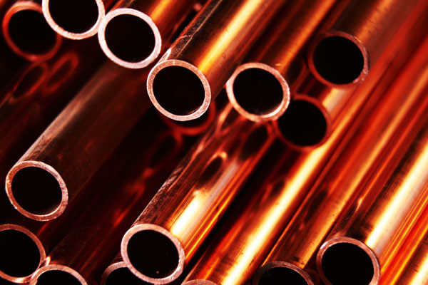
Nā Kūlana Copper ma waena o nā metala o ke kanaka, Mahalo i kāna hana uila hou, Ke kū'ē neiʻo Corrosionion, a me ka formability.
Eia hou, Ke hilinaʻi nei nāʻepekema a me nā meaʻenehana i ka hana a Copper i ka hoʻolālāʻana i nā mea e hoʻokele ai i nā mea uila.
NOEHUI, ʻO ka hoʻomaopopoʻana i keʻano o ka hoʻomaʻemaʻeʻana o Copper i lilo i insispernsible ma nā noi a me nā noi pili.
2. ʻO ka wehewehe a me keʻano o ka manaʻo o ka Menoting
'Ōlelo Malting Point Hōʻike i ka mahana ma kahi o nā loli i loko o kahi wai ma lalo o nā kūlana kūlike.
I ka hoʻomaʻamaʻa, Ke kūʻai neiʻo ia i ka kaulike ma waena o nā mea paʻa paʻa paʻa a me ka huhū.
No laila, Hoʻohanaʻo Metallirgists i keʻano o keʻano e like me keʻano he bortchmark no ke kohoʻana i nā mea, Ke hoʻolālāʻana UREA, a me ka paleʻana i nā kaʻina hana.
3. ʻO keʻano o ke keleawe keleawe
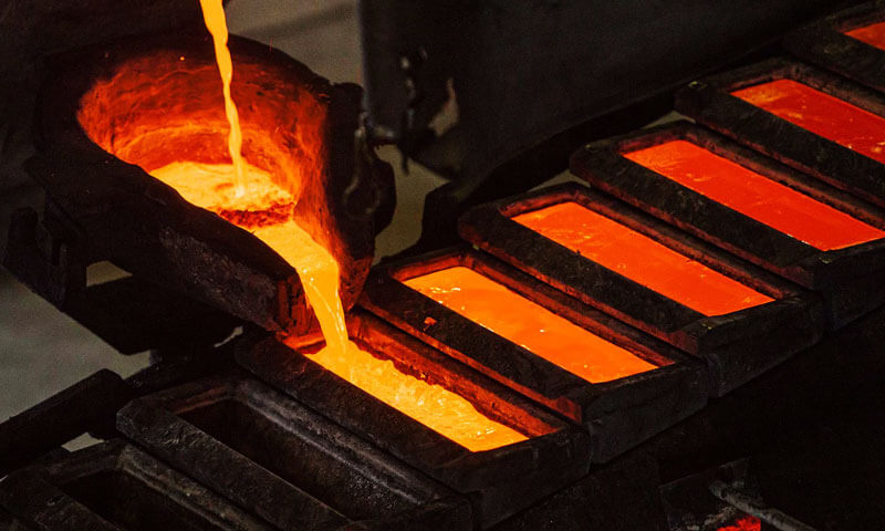
ʻO nā lole keleawe maʻemaʻe ma kahi kokoke 1,085° C (1,984° F).
Ma kēia wela, nā hana copper mai kahi paʻa i kahi wai, eʻaeʻia e hoʻoleiʻia, hui hui, a iʻole alloyed. I kānaʻano paʻa, he keleawe a cubic cub (Fcc) ʻano
4. ʻO ka nānāʻana a me ka nānāʻana o ka atomiconic
I ke kāʻei atomic, ʻO nā kumukūʻai nui o Copper ʻO ka pū metallic-ʻO ke kai o nā electronized e hoʻopili i nā mea i hoʻopiʻi maikaʻiʻia.
Kona hoʻonohonoho uila uila, [ARHERE AR] 3d¹⁰4s¹, hoʻolako i kahi mea kūʻai aku ma keʻano, ʻaʻole wale nō e hana i ka hana uila ma lalo o ka uila.
- E komo ana i ka fusion: ~ 13 KJ / MOL
- ʻO ka wela o ka wela: ~ 205 KJ / KG
ʻO kēia mau waiwai e helu ai i ka ikehu e koiʻia e wāwahi i nā mea paʻa metallic i ka wā e hoʻomālamalama ai.
Nui loa, ʻO ka nui o nā copper kiʻekiʻe kiʻekiʻe (63.55 Amu) a me ka maikaʻiʻole fcc pattice (12 nā hoalauna kokoke) hoʻokiʻekiʻe i kona ikaika ikaika a me ke kūpaʻaʻole.
5. ʻO nā mea nui e pili ana i keʻano o ka Malting Copper
ʻO kekahi mau kī nui e hoʻokaʻawale i keʻano o keʻano o keʻano, pinepine ma ka hoʻololiʻana i kona wela o ka hoʻololiʻana o ka wai-i-wai e like me nāʻumi o ke kiʻekiʻe.
Hoʻomaopopo i kēia mauʻano hoʻololi e hiki ai i ka hoʻokele mua o ke alakaʻi i ka hana maʻamau ma nāʻano kūʻai a me keʻano hana.
ʻO nā mea'ē aʻe a me nā haumia
- Zinc a tin: Ke hoʻopuka nei i ka 10-40 wt % ʻO Zn haʻahaʻa i ka neʻeʻana i ka manikoʻana ma kahi o 900-940 ° C ma ke keleawe. Like me, 5-15 wt % Sn ye chnze bronze me ka haunaele o ka unahi o 950-1,000 ° C.
- Kālā a me psphorus: Ke kala kala (≤ %) hiki iā ia ke ho'āla i ka wai keleawe e 5-10 ° C, ʻOiaiʻo phosphorus ma 0.1 wt % ho'ēmi i ka manaʻo mevering a hoʻomaikaʻi i ka uluʻana.
- Oxygen a me Sulfur: Nā Oxygen oxygen i hana i nā cu-cu-incouns ma luna 1,000 ° C, Ke hoʻohālikelike nei i keʻano o keʻano o keʻano.
I ke kumu, sulfur e hoʻohālikelikeʻia me ka haʻahaʻa e like me 0.02 wt % alakaʻi i ka embrittlement a hoʻokumu i nā elima haʻahaʻa haʻahaʻa haʻahaʻa ma nā palena palaoa.
Ka nui o ka palaoa a me nā micsstructure
- FILE VSE. Corins cunsins: Hōʻike i ka nui o ke keleawe maikaʻi loa i ka marginally kiʻekiʻe ma mua o ka marginally kiʻekiʻe-maʻamau 2-5 ° C ma mua o ka waiwai nui-no ka mea nui.
- Hoʻonui nui: I nā alloys e like me cu-be, Ua hōʻikeʻo Elipates i nā kahua kūloko kūloko e hiki ai ke hoʻonui i ka hoʻomehanaʻana e ka 8 ° C, Ke hilinaʻi nei i ka nui o ka hapa nui.
Nā hewa o ka crystal pattice
- Nā hakahaka a me nā dislocations: ʻO nāʻikena hoʻomaha kiʻekiʻe (>10⁻⁴ inomic oho) hoʻolauleʻa i ka hatttice, ka hoʻohaʻahaʻaʻana i keʻano o ka'ōpū ma 3-7 ° C.
- Hana paʻakikī: Hoʻokomoʻia nā keleawe wela, No laila, ke kaumaha nei e hoʻomehanaʻia e ka 4 ° C hoʻohālikelikeʻia i nā keleawe keleawe.
Nā hopena paʻakikī
- ʻO Claeusus-clapeyron: Hoʻonui ana ka hoʻoikaikaʻana i keʻano o ka mahana ma keʻano he nui +3 K Per 100 Mpa.
ʻOiaiʻoi aku ka nui o nā melts o nāʻoihanaʻoihana, E hōʻoia i nā hoʻokolohua kiʻekiʻe kiʻekiʻe e hōʻoia i kēia stope mua.
Nā moʻolelo a me nā kūlana
- ʻO ka hoʻomehana mua: Lohi i mua e hoʻomehana iā 400-600 ° C hiki i nā Offas i nā milities, Ke pale nei i ke kaumaha o ka wā e hoʻoheheʻe ai.
- Nāwaimaka: Pale i nā flux (E.g., Borax-pili pūʻoi aku) Hoʻokumu i kahi mea paʻa e hoʻokūkū ai i kaʻili a mālama i ka papa hana maʻamau i ka wā e wehe ai ka ea.
6. ʻO keʻano o ke aniani o nā mea kūʻai keleawe
Ma lalo he papa inoa piha o nā wahi e hoʻoheheʻeʻia no ka nui o nāʻano keleawe maʻamau.
ʻO kēia mau waiwai e pili ana i nā wela wai maʻamau; E paʻa pinepine nā alloys ma luna o kahi ākea (paʻa paʻa → wai) ka mea a mākou e'ōlelo ai maʻaneʻi e like me keʻano o keʻano haʻahaʻa.
| ALLOY NAME / Kā mākou | Ka Hoʻolālā (wt%) | Hoʻohemo melū (° C) |
|---|---|---|
| C10200 (ECD) | ≥9s.90cu | 1 083-1085 |
| C11000 (Electrolytic cu) | ≥9s.90cu | 1 083-1085 |
| C23000 (Hiila mele) | ~ 67ccu-45zn | 900 -920 |
| C26000 (Keleawe cretridge) | ~ 70cu-30zn | 920 -940 |
| C36000 (ʻO ke keleawe manuahi manuahi) | ~ 61cu-38zn-1pb | 920 -940 |
| C46400 (Nāʻili manu) | ~ 60cu-39zn-1sn | 910 -960 |
| C51000 (Phosphor Bronze) | ~ 95CU-5SN | 1 000-1050 |
| C52100 (Nā pou ikaika kiʻekiʻe. Bronze) | ~ 94cu-6sn | 1 000-1050 |
| C61400 (Ailunimina bronze) | ~ 82cu-10AL-8FF | 1 05-1035 |
| C95400 (Ailunimina bronze) | ~ 79 Cu‑10 Al‑6 Ni‑3 Fe | 1 020-445 |
| C83600 (Ke keleaweʻulaʻula) | ~ 84cu-6sn-5pb-5zn | 890 -940 |
| C90500 (ʻO Gun Metal) | ~ 88cu-10sn-2zn | 900 -950 |
| C93200 (Silikino Bronze) | ~ 95s. | 1 000-1050 |
| C70600 (90-10 cuprockel) | 90 Me 10ni | 1 050-1150 |
| C71500 (70-30 cuponcker) | 70 Me-30ni | 1 200-1300 |
| C17200 (Beyreellium Kina) | ~ 97cu-2be-1co | 865 -1000 |
7. ʻO ka hoʻohālikelikeʻana i keʻano o ka koho balota
Ua hoʻololiʻo Copper i keʻano o ka Copper i kahi manawa e komo ai nā ala alloying.
I ka hoʻomaʻamaʻa, ʻO nā Metallirgists e hoʻohana i kēia mauʻano likeʻole i ka hanaʻana i nā wela wela, kaulikeia, A me ka hana mechanical.
Ka hopena o nā mea'ē aʻe
- Zinc (Zn):
Hoʻohui i 10-40 wt % Zn e hana i nā mea haʻahaʻa haʻahaʻa haʻahaʻa i ka waihoʻoluʻu 900-940 ° C, Mahalo i ka cu-zn eutectic ma ~ 39 wt % Zn (melting on ~ 900 ° C).
ʻO nāʻekolu keleawe zinc kiʻekiʻe (Nā luna 35 % Zn) hoʻomaka e hoʻokokoke i keʻano o nā mea etuctic, Ke hōʻike nei i kahi mea kākau moʻolelo me keʻano o keʻano o keʻano a me keʻano nui. - Kū (Sno):
Ka hoʻolaunaʻana iā 5-15 WT % Sn ye chnze bronze me kahi interval o 950-1,000 ° C.
Iiiai, Hōʻike ka pahu o ka cu-s-s-s-sn i kahi etuctic ma ~ 8 wt % Sno (~ 875 ° C), Akā e hana ana i nā mea hoʻolālā bronze bronze ma mua o kēlā, e kaomi ana i ka wai wai kokoke 1,000 ° C e hōʻoia i ka ikaika kūpono. - Nickel (I):
I nā kīʻaha kīʻaha (10-30 wt % I), E piʻi mai ka wai wai mai 1,050 ° C (no ka 10 % I) a i 1,200 ° C (no ka 30 % I).
ʻO ka ikaika ikaika o Nicicl no ka lanakilaʻana o ka Copper i ka ikaika ikaika a hoʻololi i ka paʻa a me nā mea i luna. - Aluminum (AL):
Ailuninil bronzes (5-11 wt % AL) hoʻoheheʻe ma waena 1,020-1,050 ° C.
Ua hōʻikeʻia kā lākou kiʻi kiʻi o kā lākou papa; kahi mea nui a puni 10 % E hele ana ma ~ 1,010 ° C, akā, pono nā mea kiʻekiʻe-al alloys i nā wela ma luna 1,040 ° C i ka wai piha. - Beryllium (E Maʻa):
ʻO nā hoʻohui liʻiliʻi (~ 2 wt %) o ka ho'ēmiʻana i keʻano o ka haunaele i 865-1,000 ° C Ma ka hoʻolahaʻana i kahi kūpono o keʻano haʻahaʻa 2 % E Maʻa (~ 780 ° C).
Ke hana nei kēia hana i ka hana kūpono akā e koi i nā mea mālama olakino olakino-a-palekana palekana i ka wā o ka hoʻohaʻahaʻaʻana.
Nā hopena maikaʻi a me nā hopena paʻa
- Pūnaehana Entictic: Allys i a iʻole kokoke i nā hoʻohuihui Eutectic i kūpono i hoʻokahi, ʻO keʻano nui-kūpono no ka makeʻana o ka makeʻana a iʻole nā pā hale.
ʻo kahi laʻana, he cu-zn alloy i 39 % Rn solidifies ma 900 ° C, ʻO ka hoʻonuiʻana i ka wai. - Nā hopena paʻa: Sub-etutectic a iʻole hypo-etutectic alloys exhibit e hōʻike ana i kahi ākea (paʻa i ka wai).
Hiki i nā RADE RENEST ke kumu "Mushy" Zones i ka wā hoʻoponopono, ʻO ka hoʻopiʻiʻana i ka segregeation a me ka poosity. Ma ka hoʻohālikelike, Hiki i nā alloys hyperct.
8. Ka pilina o kaʻoihana o keʻano o ke keleawe
ʻO keʻano o keʻano o ka colping 1 085 ° C (1 984 ° F) E hoʻokani i kahi hana pivotal i loko o nā hana nui a pau i hanaʻia e nā mea hoʻololi e hoʻololi ai i nā mea i pau.
I ka hoʻomaʻamaʻa, Hoʻohana nā mea hana i kēia waiwai e koho i ka hoʻohana ikaika, E kāohi i ka maikaʻi huahana, a ho'ēmi hōʻemi.
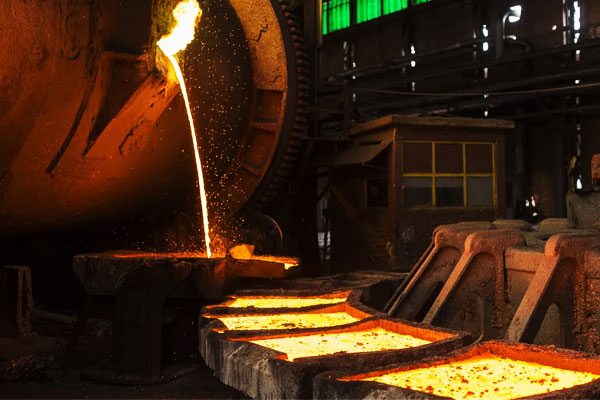
Smelking a me kaʻoluʻolu
Loaʻa a me nā smelters i nā mea kūʻai aku i ke keleawe wela e ulu ana i 1 200-1 300 ° C, ʻoi aku ka maikaʻi o ka melting metal e hōʻoia i ka hoʻokaʻawaleʻana i ka hoʻokaʻawaleʻana.
Ma ka mālamaʻana i ka umu ma kahi 1 100 ° C, Hoʻemi nā mea hana i nā pohō oxidation: Hiki i nā kaʻina hana pono ke hōʻoki i ka hanaʻana i ka hanaʻana mai 4 % iho i lalo 1 %.
Nui loa, ʻO nā mea kanu Electrorefining i nā mea e hoʻomanaʻo ana e ka haʻaleleʻana i nā anides i nā mea hoʻonā Acidic, Akā, hilinaʻi mau lākou i nā maʻi mua e hoʻolei i nā papa kiʻekiʻe kiʻekiʻe.
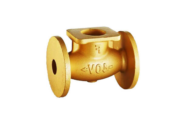
Ke kāwele a me ka hanaʻana i ka hana
Ke hana nei i ke keleawe, bronze, a iʻole nā mea hao aluminum, Hoʻokumuʻia nāʻenehana i nā wela ma mua o kēlā me kēia alloy wai.
ʻo kahi laʻana, 70/30 ʻO ke keleawe keleawe ma kahi 920 ° C, oiai 6 % Ponoʻo Aluminum Bronze 1 040 ° C.
I ka hoʻopaʻaʻana i kaʻauʻau i loko o kahi'āpana ± 5 ° C pukaaniani, hoʻokō lākou i ka hui molld piha, Hoʻemi i ka poosity e ka 30 %, a e hōʻoia i ka chessisty alloy.
ʻO ka mālamaʻana a me ka hoʻokeleʻana
No ka mea,ʻoi aku ka ikaika o ka copper coprit me ka oxygen, Nui nā mea hou i hoʻihoʻiʻia a iʻole nā mea hana hoihoi argon a nitrogen shrouds.
ʻO kēia mau mea i loko o nā pohō haʻahaʻa haʻahaʻa haʻahaʻa 2 % (wehe-ea) i lalo 0.5 %, Ma laila ka hoʻomaikaʻiʻana i ka palekana a me ka hana uila no nā mea koʻikoʻi e like me nā mea pena e like me nā pale kaʻa a me nā mea hoʻolaha.
Recycling a me ka hana ikaika
Recycling scrap crap i loaʻa a i 85 % ka nui o ka ikehu ma mua o ka hana mua.
Akā naʻe,, Loaʻa pinepineʻia ka SCHED-Alloy Scrap i nā keleawe a me nā bronzes me nā helu wai i ka nui 900 ° C i 1 050 ° C.
ʻO nā'ōnaehana hoʻololiʻana i kēia mau papa hana hou e hana ai i nā mea hana regenerative regenerative a me ka ho'ōla wela wela, ʻO ka hoʻohanaʻana i ka hoʻohanaʻana i ka mana holoʻokoʻa 15-20 %.
Ma ka hopena, Ua hāʻawi akuʻo Ciry Brow i kēia manawa 30 % o nā lako honua, e alakaʻiʻia e nā mālama kālā a me nā pono o nā kaiāulu.
9. Nā noi e koi ana i ka mana o ka hoʻomālamalama
ʻO kekahi mau hana hana i noi aku i ka hoʻoponoponoʻokoʻaʻana i ka pāʻoihana paʻa e pili ana i ka hoʻohuiʻana o China me ka hōʻoiaʻana i ka maikaʻi, Hana, a me ka hoihoi.
Ma lalo, Ke nānā nei mākou i nā noi heʻekolu e pili ana i ka hinge i ka mana o ka lalo.
Kāhaka kūʻai kūʻai
I Kāhaka kūʻai kūʻai, Loaʻa nāʻike i nā mahana i loko ± 5 ° C o ka wai o ka alloy e hōʻoia i ka hoʻopihaʻana i nā mea e hoʻopihapiha ai a hōʻemi i ka poosity.
ʻo kahi laʻana, Ke hoʻolei nei i kahi phosphor-bronze i luna (wai ~ 1,000 ° C), Mālama pinepine nā mea hana i kaʻauʻau ma 1,005 ° C.
Ma ka hana, hoʻokō lākou i ka hoʻopili piha pihaʻole me kaʻole overheting, ka mea e hōʻole ai i ka hōʻoiaʻana i ka dimensional pololei a hoʻonui i ka hoʻokumuʻana i ka hana.
ʻO ka hana keleawe kiʻekiʻe kiʻekiʻe no ka hoʻohana uila uila
Nā mea hana o nā keleawe uila uila (≥ 99.99 % Cu) hoʻokō i lalo o ka hakahaka ma lalo o ka hakahaka a iʻole ka haunaele, ka paleʻana i ke aniani i loko ± 2 ° C na 1,083 ° C.
Mālama kēia i ka mana o ke kikowaena o ka mīkini a me keʻano, nā meaʻelua o ka hoʻokō.
Eia hou, ʻO ka hoʻokele waiwai paʻa i ka hana mauʻana i nā laina e hāʻawi hou ana i nā hana palaoa maikaʻi e hoʻomaikaʻi hou aku i ka hana uila ma lalo nei 1.67 ■-cm.
Hoʻohui hoʻohui a me ka loaʻaʻana o nā kiʻiʻoniʻoni
I ka waser powder-fausion (Lpbf) o na keleawe keleawe, Hoʻoponopono nāʻenehana i ka mana Laser a me Scan wikiwiki e hana ai i nā Pools Point Pools 1,100 - 1,150 ° C.
Ua nānā pinepineʻia nā mea hōʻike hewa loa i ka manawa maoli me nā pyrometers, Potiwale, a me nā kiʻina maikaʻi.
Like me, I ka waihoʻana o ka vapor kino kino (Pvd) nā kiʻi keleawe, Pono nā mahana maikaʻi i loko o loko ± 1 ° C o ka setoint setoist (maki 1,300 ° C) E kāohi i nā helu kau inoa a me nā kiʻi kiʻi kiʻi kiʻi i lalo i kaʻaoʻao o Nanometer.
10. Nā hoʻohālikelike me nā metala'ē aʻe
Ke hoʻohālikelike nei i ka hoʻohālikelikeʻana o nā Copper i kahi Spectrum Sporctrum o nā metala e wehewehe hou ana i keʻano o keʻano o ka mea hana.
ʻO nā māka me nā wahi paʻa
| Mea meta | Malting Point (° C) | Ikaika ikaika (kj / mol) | ʻO ka hoʻolālā crystal |
|---|---|---|---|
| Magnesum | 650 | 75 | Hcp |
| Zinc | 420 | 115 | Hcp |
| Alakaʻi | 327 | 94 | Fcc |
| Aluminum | 660 | 106 | Fcc |
| Dala | 961 | 216 | Fcc |
| Gula | 1 064 | 226 | Fcc |
| Liulaala | 1 085 | 201 | Fcc |
| 'Lelo'Slelo | 1 495 | 243 | Hcp (α-co) |
| Nickel | 1 455 | 273 | Fcc |
| Titanium | 1 668 | 243 | Hcp (α-ti) |
| 'Eron | 1 538 | 272 | Bcc (Δ-FE), Fcc (γ-fe) |
| Papa | 1 768 | 315 | Fcc |
| Tungsten | 3 422 | 820 | Bcc |
Nā hopena no ka hoʻolālāʻana
- Ikaika a me ke kumukuai: Metalas e like me ke keleawe keleawe i kahi kaulike ma waena o nā wela kūpono (a puni 1 085 ° C) a me nā mea pono ikaika.
Ma ka hoʻohālikelike, ʻO ka hoʻoiliʻana i ka Trungsten a iʻole Platinum e pono ai i nā lako kiʻekiʻe kiʻekiʻe a me nā mea waiwai nui loa. - Hui pū a me ka hale noho: Ke hoʻohui pūʻana i nā metala dissimular, e like me ka braping keleawe i titanium,
Koho i nā mīkini i koho i nā mea hoʻopiʻi me nā wahi e melving ma lalo o ka metala haʻahaʻa haʻahaʻa e pale aku ai i nā hōʻino kino. - Hana afe: Ua hoʻolimalima nā mea hoʻolālā a Alloy i kēia mau leʻaleʻa a me ka hāʻawiʻana i nā hōʻailona i nā meaʻenehana e hana ai ma lalo o nā kūlana kūpono,
Inā makemake lākou i kahiʻano haʻahaʻa haʻahaʻa haʻahaʻa a iʻole kahiʻano kiʻekiʻe kiʻekiʻe.
11. Hopena
ʻO keʻano o ke kāʻei o ke keleawe a me nā mea kūʻai akuʻo nā mea koho back a me nā kaulike ma waena o nā mea kaulike ikaika a me nā pono hana hana.
Loaʻa nāʻenehana i ka hana maikaʻi loa, Kauhi, a me ka hana holomuaʻana e nā paleʻana i nā haumia, nā mea'ē aʻe, a me nā kaʻina hana.
E like me nā mea hana e hoʻoikaika ai i nā hana ikaika e pono ai a me nā mea waiwai nui, ʻO kahi kāhiko o ka hanaʻana o keʻano o keʻano o keʻano o keʻano o keʻano o keʻano he kumu koʻikoʻi no ka hana houʻana.
FaqS
Pehea ka mea e hoʻoheheʻe ai i keʻano o ke keleawe?
E koho i nā limahana i nā pihi Melting Copper i ka hoʻohanaʻana i ka carlimetryʻokoʻa (Dsc) a iʻole he mea ulu ulu kiʻekiʻe a iʻole nā mea hoʻonaninani kiʻekiʻe me nā thermocounds calibrated.
ʻO kēia mau hiʻohiʻona wela e wela i nā helu i hoʻopaʻaʻia (maʻamau 5-10 ° C / min) a hoʻopaʻa i ka oneset o ka hoʻololiʻana o ka wai-wai.
He aha nā mea nui e hoʻoikaika ikaika ai i keʻano o keʻano o ke keleawe?
Zinc a me TIN nui i ka wai o ke keleawe haʻahaʻa haʻahaʻa (i 900-940 ° C i loko o nā keleawe a me 950-1,000 ° C ma Bronzes). Like, Hiki i ke kala ke ho'āla iā ia ma 5-10 ° C.
ʻO ka oxygen a me Sulfur pinepine i nā momi i nā momi i lalo a iʻole nā sulfie, e hana ana i nā minamina haʻahaʻa.

