1. مقدمة
تشير "الصفائح المعدنية" عادةً إلى مخزون المعادن تقريبًا 0.2 ملم الى 6 مم سماكة (تختلف تعريفات الصناعة).
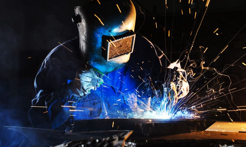
اللحام على هذا النطاق هو عمل متوازن: توفير طاقة كافية لمفصل سليم مع تقليل التشوه, الحرق والأضرار المعدنية.
تتطلب النتائج الجيدة اختيار العملية المناسبة (بقعة, قوس, احتكاك, الليزر, النحومة), السيطرة على مدخلات الحرارة, التصميم المشترك الصحيح والتفتيش القوي.
2. ما هو لحام الصفائح المعدنية?
لحام الصفائح المعدنية هي مجموعة من تقنيات الانضمام المستخدمة لإنشاء الهياكل الهيكلية, مفاصل وظيفية أو تجميلية مصنوعة من مخزون معدني رفيع — عادة من ≈0.2 مم حتى 6 مم سمك في الممارسة الصناعية.
في هذا المقياس، تختلف الأهداف عن اللحام بالقسم الثقيل: يجب عليك إنتاج مفصل سليم أثناء التقليل من مدخلات الحرارة, تجنب الاحتراق, السيطرة على التشويه, والحفاظ على الانتهاء من السطح للتجميع النهائي أو الألواح المرئية.
تعريف موجز
لحام الصفائح المعدنية هو التطبيق المحلي المتحكم فيه للطاقة (الحرارية, الاحتكاك أو المعدنية) لدمج أو ربط مكونين أو أكثر من الصفائح المعدنية بحيث يفي المفصل بالمتطلبات قوة, تعب, التآكل ومستحضرات التجميل معايير, مع إبقاء التشويه وإعادة العمل ضمن الحدود المقبولة.
ما يتضمنه (عائلات العملية)
لا يعد لحام الصفائح المعدنية تقنية واحدة، بل هو مجموعة من الطرق المختارة لتناسب المواد, سماكة, الهندسة المشتركة وحجم الإنتاج:
- لحام الانصهار - يذيب المعدن الأصلي ويضيف عادة مادة حشو (على سبيل المثال, GMAW/ميج, جي تي إيه دبليو/تي آي جي, الليزر, بلازما).
- اللحام بالمقاومة — يولد الحرارة عن طريق المقاومة الكهربائية في الواجهة (على سبيل المثال, اللحام بقعة).
- لحام الحالة الصلبة - ينضم دون ذوبان (على سبيل المثال, لحام الاحتكاك (FSW)).
- اللحام واللحام — التدفق الشعري لمعدن حشو منخفض الذوبان لربط الأجزاء الرقيقة دون ذوبان المعدن الأساسي.
- التثبيت الميكانيكي (المسامير, حسم) وتستخدم المواد اللاصقة أحيانًا مع اللحام.
3. عمليات اللحام الشائعة للصفائح المعدنية - في العمق
يستخدم تصنيع الصفائح المعدنية مجموعة صغيرة من تقنيات اللحام والربط المختارة للتحكم في مدخلات الحرارة, تشويه, المظهر ووقت الدورة.
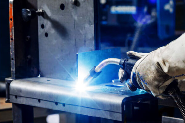
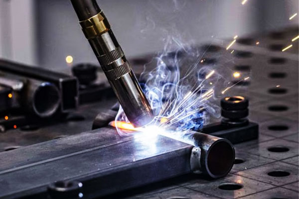
لحام القوس المعدني بالغاز (GMAW / أنا)
يشكل GMAW قوسًا كهربائيًا بين قطب الأسلاك المستهلكة الذي يتم تغذيته بشكل مستمر وقطعة العمل.
القوس يؤين الغلاف الجوي للغاز التدريعي, إنتاج عمود بلازما ينقل الطاقة الحرارية إلى طرف السلك وإلى سطح قطعة العمل.
يتم نقل المعدن من السلك إلى حوض اللحام في أوضاع منفصلة يحددها التيار, قطر السلك, كيمياء الأسلاك, تكوين الغاز وديناميكيات القوس:
- نقل ماس كهربائى: يتصل الطرف المنصهر بقطعة العمل لفترة وجيزة وتتسبب المسامير الحالية في انفصال القطرات بسرعة; الطاقة لكل قطرة منخفضة, مما يوفر اختراقًا محدودًا والحد الأدنى من إدخال الحرارة - مثالي للألواح الرقيقة جدًا.
- نقل كروي: أكبر, تتشكل القطرات المتأثرة بالجاذبية وتسقط; هذا الوضع غير مستقر وينتج عنه تناثر.
- نقل الرذاذ: عالية الحالية, النقل المستمر للقطرات الدقيقة عبر القوس; ترسيب عالي واختراق عميق ولكن مدخلات حرارة أعلى (أكثر ملاءمة للأقسام السميكة).
- رذاذ نابض: شكل موجي لتيار الذروة والقاعدة يتم التحكم فيه والذي ينتج نقل قطرة واحدة لكل نبضة - يجمع بين متوسط دخل الحرارة المنخفض وفصل القطرات الشبيه بالرش للحصول على لمسة نهائية جيدة على الصفائح الرقيقة إلى المتوسطة.
القوى الكهرومغناطيسية (تأثير قرصة) والتوتر السطحي يحكم تكوين القطرات وانفصالها.
ديناميات تجمع اللحام (تدفق السوائل, الحمل الحراري المارانجوني يتأثر بالكبريت / الأكسجين, والتحريك الكهرومغناطيسي) السيطرة على شكل حبة والتخفيف.
يؤثر تكوين الغاز التدريعي على استقرار القوس, وضع نقل المعادن والاختراق (على سبيل المثال, يزيد ثاني أكسيد الكربون من حجم القطرات والتناثر; تعمل مخاليط الأرجون والأكسجين على تثبيت نقل الرش عند التيارات المنخفضة).
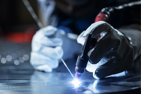
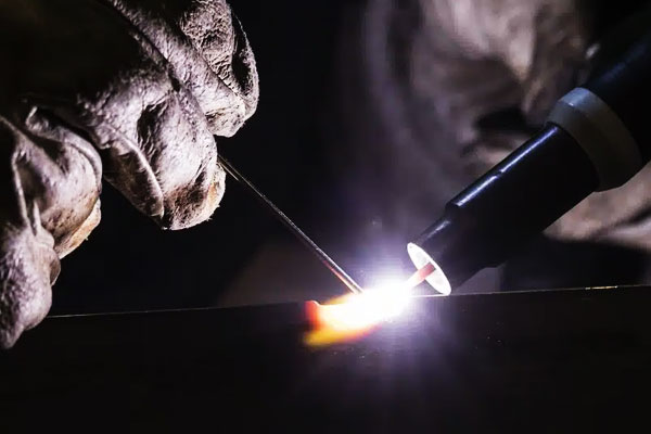
لحام قوس الغاز التنغستن (GTAW / تيج)
يستخدم GTAW أ قطب التنغستن غير القابل للاستهلاك للحفاظ على قوس مستقر.
القوس مقيد ويرتبط بالمعدن الأساسي, نقل الحرارة من خلال الغاز المتأين (بلازما).
منذ لا يتم استهلاك القطب, معدن حشو (إذا تم استخدامه) يتم تغذيته يدويًا أو تلقائيًا في حوض اللحام.
الجوانب المادية الرئيسية:
- عمود القوس وتركيز الحرارة: أقواس TIG ضيقة ويمكن التحكم فيها بشكل كبير; التغييرات الصغيرة في زاوية التيار أو الشعلة لها تأثيرات مباشرة على مدخلات الحرارة المحلية.
- التدريع وكيمياء القوس: غاز خامل (الأرجون عادة) يمنع الأكسدة; للألمنيوم AC TIG,
القطبية المتناوبة تخلق تنظيفًا للأكسيد (التلميع الكهربائي) التأثير خلال نصف دورة القطب الموجب والاختراق خلال نصف دورة القطب السالب - وهذا أمر بالغ الأهمية لكسر جلد أكسيد الألومنيوم العنيد. - التوصيل الحراري والتبريد الإشعاعي: لأن القطب يكون أكثر برودة وتتدفق الحرارة إلى قطعة العمل, تنتج TIG منطقة اندماج يمكن التنبؤ بها مع تحكم دقيق في حجم البركة.
- بدء القوس والاستقرار: تتيح الأنظمة عالية التردد أو أنظمة رفع التشغيل بدء القوس المتحكم فيه دون تلوث; اختيار القطب (مصعّر, سيرياتد, لانثاناتيد) يصمم انبعاث الإلكترون واستقرار القوس لنطاقات تيار مختلفة.
يسمح TIG بالتحكم الحراري الدقيق والحد الأدنى من اضطراب حوض السباحة المنصهر, مما يجعلها ممتازة للصفائح الرقيقة واللحامات التجميلية حيث يهيمن استقرار القوس والنظافة على الأداء.
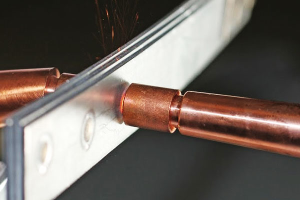
لحام البقعة المقاومة (RSW)
اللحام البقعي بالمقاومة هو أ عملية تسخين جول: يتم دفع التيار العالي من خلال كومة صفائح التلامس بينما تحافظ قوة القطب الكهربائي الضاغطة على الاتصال الحميم.
المقاومة المحلية في واجهة الاتصال (وبدرجة أقل مقاومة الصفائح السائبة) يحول الطاقة الكهربائية إلى حرارة بسرعة, مما تسبب في ذوبان محلي وتشكيل الكتلة اللحام.
نقاط ميكانيكية مهمة:
- مقاومة الاتصال مقابل المقاومة السائبة: مقاومة الواجهة الأولية تهيمن على التدفئة; حيث تلين المواد ويتشكل المعدن المنصهر, تتغير المقاومة ديناميكيًا - يجب أن يأخذ التحكم في العملية في الاعتبار هذا التحول.
- قوة القطب وتوزيع الحرارة: قوة الضغط تضغط على الأكاسيد وتقلل من مقاومة التلامس; كما أنه يتحكم في هندسة الكتلة عن طريق تقييد المعدن المنصهر ومنع طرده.
- الانتشار الحراري والتبريد: بعد قطع التيار, يستخرج وقت الانتظار وتبريد القطب الحرارة ويصلب الكتلة الصلبة; تبريد القطب (أقطاب النحاس المبردة بالماء) أمر بالغ الأهمية للتحكم في حجم الكتلة والتكرار.
- آثار المواد والطلاء: الطلاءات (الجلفنة, الطلاءات العضوية) تغيير مقاومة التلامس وقد يتبخر, التي تؤثر على توطين الحرارة وعمر القطب - يجب تعديل الجداول الزمنية وفقًا لذلك.
RSW هي في الأساس عملية كهروميكانيكية حرارية حيث يتم استخدام الكهرباء, تتفاعل المتغيرات الحرارية والميكانيكية على فترات زمنية بالمللي ثانية لإنتاج رابطة معدنية.
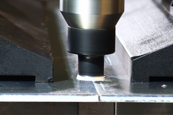
تحريك الاحتكاك (FSW)
FSW هو أ الحالة الصلبة, عملية الانضمام الحرارية الميكانيكية. الدورية, أداة لمحة (كتف + دبوس) يغرق في المفصل ويمر عبره.
وتشمل آليات العمل:
- التدفئة الاحتكاكية: يقوم الكتف والدبوس الدواران بتوليد الحرارة عن طريق الاحتكاك في واجهة قطعة العمل والأداة, رفع درجة الحرارة محليًا إلى حالة قابلة للتدفق من الناحية البلاستيكية ولكن شبه ذوبان.
- تدفق المواد الملدنة والتحريك: تجبر هندسة الدبوس المواد من الحافة الأمامية على التدفق حول الدبوس وتتماسك في أعقاب ذلك, إغلاق الفراغات وتكسير أفلام الأكسيد الأولية - مما يؤدي إلى "منطقة تحريك" دقيقة الحبيبات مُعاد بلورتها ديناميكيًا.
- عمل تزوير الميكانيكية: الكتف يمارس الضغط, توحيد المادة المقلبة وإنتاج وصلة خالية من العيوب مع عدم وجود مسامية مرتبطة بالاندماج.
- تطور البنية الدقيقة: يعمل التشوه البلاستيكي الشديد وإعادة البلورة الديناميكية على تحسين الحبوب وغالبًا ما تنتج خواص ميكانيكية فائقة مقارنةً باللحامات الاندماجية.
لأن FSW يتجنب الذوبان, فهو يزيل عيوب التصلب (على سبيل المثال, المسامية, تكسير ساخن) وتنتج تشويه منخفض; لكن, يتطلب اللحام الناجح دعمًا صارمًا وتحكمًا دقيقًا في هندسة الأداة وحركيات العملية.
لحام شعاع الليزر (LBW) & اللحام القوسي بالليزر الهجين
ينقل اللحام بالليزر الطاقة في شعاع موازٍ للغاية يقترن بالسطح, إنتاج وضعين التوصيل الأساسي:
- وضع التوصيل: عند كثافة طاقة أقل، يقوم الليزر بتسخين السطح ويذيب المادة عن طريق التوصيل; الاختراق هو منطقة ضحلة ومتأثرة بالحرارة (المخاطر) متواضع.
- وضع ثقب المفتاح: عند كثافات الطاقة العالية، يبخر الشعاع عمودًا من المعدن مما يخلق تجويفًا مملوءًا بالبخار (ثقب المفتاح). يؤدي الامتصاص المكثف عند جدران ثقب المفتاح إلى اختراق عميق حيث يتم الحفاظ على ثقب المفتاح; يتحكم ضغط الارتداد وديناميكيات السوائل حول ثقب المفتاح في تدفق واستقرار حوض السباحة المنصهر.
وتشمل العوامل المادية الرئيسية امتصاص (مادة, حالة السطح), الانعكاسية (تعمل المعادن شديدة الانعكاس مثل Al وCu على تقليل الاقتران), واستقرار ثقب المفتاح (حساسة لتركيب المفاصل ووجود الملوثات).
اللحام بقوس الليزر الهجين يجمع بين الليزر والقوس (عادة ميغ) — القوس يحسن سد الفجوات, يقوم بتسخين المفصل وتزويد الحشو بينما يوفر الليزر اختراقًا عميقًا ومناطق منطقة ضيقة.
ينشأ التآزر لأن القوس يزيد من توافر المعدن المنصهر ويقلل الحساسية للفجوات البسيطة, بينما يتحكم الليزر في الاختراق ويقلل من التشويه.
لحام قوس البلازما (مخلب)
يولد PAW طائرة بلازما مقيدة عن طريق إجبار غاز البلازما (الأرجون, يمزج الهيدروجين) من خلال فوهة دقيقة حول قطب التنغستن.
يؤدي الانقباض إلى رفع درجة حرارة الغاز والتأين, إنتاج مركزة, قوس عالي الكثافة للطاقة يمكن استخدامه في أي منهما:
- الوضع المنقول: يعلق القوس على قطعة العمل ويتركز نقل الحرارة; مناسبة لاختراق أعمق.
- غير منقولة (طيار) وضع: يتم الحفاظ على القوس بين القطب الكهربائي والفوهة لمهام التسخين المسبق أو الإشعال المتخصصة.
تنتج كثافة الطاقة العالية والتدفق الصفحي لطائرة البلازما اختراقًا مستقرًا مع تحكم أفضل من TIG التقليدي;
كيمياء الغاز (إضافة H₂) يزيد من المحتوى الحراري والاختراق على حساب التقاط الهيدروجين المحتمل في السبائك الحساسة.
وبالتالي فإن هندسة الفوهة والتحكم في تدفق الغاز تعتبر من العوامل الحاسمة لشكل القوس, الاختراق وسلوك تجمع اللحام.
وقود أوكسي, اللحام واللحام (لقياس رقيقة, غير هيكلية)
هذه هي طرق الانضمام الشعرية والتحكم في درجة الحرارة بدلا من اللحام الانصهار:
- وقود أوكسي (لهب) اللحام/النحاس: لهب الاحتراق (O₂ + غاز الوقود) يزود بالحرارة الموضعية.
في لحام سبائك الحشو (مع نقطة انصهار تحت المعدن الأساسي) يتم تسخينه ليتدفق عن طريق الشعرية إلى الخلوص المشترك دون ذوبان المعادن الأساسية.
تعمل كيمياء اللهب والتدفق على إدارة ذوبان الأكسيد وترطيبه. اللحام بالوقود الاوكسيجيني (الانصهار) يذيب المادة الأصلية والحشو - وهو أمر نادر في الأعمال الورقية بسبب التحكم في الحرارة الخشنة. - النحومة: يعتمد على ترطيب- يجب أن يتدفق الحشو المنصهر ويلتصق بالأسطح المعدنية الأساسية, إزاحة الأكاسيد; تعمل التدفقات أو الأجواء الخاضعة للرقابة على إزالة الأكاسيد وتعزيز الترطيب.
يتحكم العمل الشعري في توزيع الحشو; التخليص المشترك أمر بالغ الأهمية (الخلوص المختلط النموذجي 0.05-0.15 ملم). - لحام: مشابهة للنحاس ولكن في درجات حرارة أقل (<450 درجة مئوية); يتحكم التوتر السطحي والتصلب في سلامة المفاصل في الإلكترونيات وتجميعات الضوء.
لأن المعادن الأساسية لا تذوب, ينتج عن اللحام والنحاس الحد الأدنى من التشويه وهو مناسب تمامًا لربط المعادن المتباينة; النجاح يعتمد على تعدين الحشو, كيمياء التدفق ومراقبة صارمة للنظافة والتخليص.
4. الاعتبارات المادية وقابلية اللحام
لحام الصفائح المعدنية هو نفس القدر السلوك المادي كما هو الحال حول اختيار العملية.
تستجيب السبائك المختلفة للتسخين بشكل مختلف تمامًا, صب, التصلب والتبريد:
تتحكم الموصلية الحرارية في كيفية انتشار الحرارة, تتحكم كيمياء السبائك في قابلية التشقق وخصائص ما بعد اللحام, وتتحكم حالة السطح في استقرار القوس والمسامية.
| مجموعة المواد | قابلية اللحام (ملزمة) | العمليات النموذجية | المخاوف الرئيسية / الآثار | حشو نموذجي & التدريع |
| فولاذ الكربون / الفولاذ منخفضة الفولاذ | جيد → مشروط | GMAW (ماس كهربائى/نبض), GTAW, RSW | تصلب HAZ على الأجزاء الأعلى من C أو السميكة; تشويه; التكسير البارد الناتج عن الهيدروجين في حالة وجود رطوبة/ملوثات | ER70S-6 (أنا); يمزج Ar/CO₂; التسخين المسبق/التسخين اللاحق للفولاذ العالي CE |
| الفولاذ المقاوم للصدأ (الأوستنيتي) | جيد جدًا | GTAW, GMAW نابض, الليزر | التحسس (هطول كربيد) إذا كان محموما → التآكل; منطقة ضيقة; السيطرة على التشويه | ER308L / ER316L (حشو منخفض C), 100% AR (تيج), يمزج ع (أنا) |
| الفولاذ المقاوم للصدأ (الحديدي / المارتنسيتي) | تحدي | تيج, MIG مع التسخين المسبق | مارتنسيتي: خطر تصلب وتكسير HAZ; الحديدي: نمو الحبوب & هشاشة | مارتنسيتي: حشو مطابق + تقسية ما بعد اللحام; السيطرة على التسخين (100-300 درجة مئوية) |
الألومنيوم & سبائك |
جيد - عملية حساسة | تيج (تكييف), نبض لي (بكرة بندقية), الليزر, FSW | الموصلية الحرارية العالية; أكسيد عنيد (al₂o₃) يحتاج إلى إزالة; المسامية ومخاطر التكسير الساخن في بعض السبائك | آل الحشو: ER4043 (و, سيولة جيدة), ER5356 (ملغ, قوة أعلى); 100% ع أو ع / هو |
| نحاس, النحاس, برونزية | معتدل → التعامل الخاص | تيج, الليزر, النحومة (يفضل للنحافة) | الموصلية العالية جدا (النحاس) → فقدان الحرارة; يطلق النحاس أبخرة الزنك; خطر الاحتراق والتبخر | نحاس: حشو النحاس سي; النحاس: حشو مختلط; التدريع الأرجون; تهوية جيدة |
| المجلفن / الفولاذ المطلي | تعتمد على الحالة | MIG/TIG مع الشريط المحلي, RSW (مع الضوابط), ليزر + استخراج | يتبخر الزنك → المسامية, ترشيش والأبخرة السامة (حمى الدخان المعدني); تقليل عمر القطب في RSW | طلاء الشريط في منطقة اللحام أو استخدام الاستخلاص المحلي; معدات الوقاية الشخصية والسيطرة على الدخان إلزامية |
5. التصميم المشترك, إعداد الملاءمة والحافة
تصميم مشترك جيد يقلل من متطلبات مدخلات الحرارة ويحسن الجودة.
- مفاصل اللفة شائعة في اللحام البقعي و MIG للصفائح; احذر من المياه المحتبسة أو جيوب التآكل.
- مفاصل المؤخرة على ورقة رقيقة تتطلب إعدادًا ممتازًا للحافة (مربع, فجوة قريبة) لليزر أو TIG. فجوة الجذر عادة 0-0.5 ملم لليزر; قد تتحمل TIG المزيد.
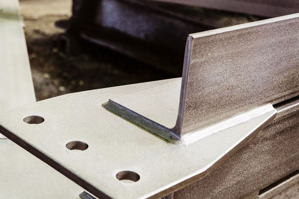
- اللحامات فيليه: للقوة والصلابة, الحد من حجم الحلق لتجنب الحرق. ساق فيليه نموذجية ل 1 يبلغ حجم الورقة مم حوالي 1-2 مم ولكن يجب التحكم فيها بعناية.
- حواف الحواف: ليست هناك حاجة عادة للصفائح الرقيقة; إذا تم استخدامه, أبقِ الشطبة ضحلة لتجنب الحشو الزائد والحرارة.
- التسامح: لليزر وFSW, التحمل المناسب ضيق (±0.1 ملم أو أفضل). لـ MIG/TIG على مواد رقيقة جدًا, الفجوات <0.5 ملم شائعة لتجنب الاحتراق.
6. مدخلات الحرارة, السيطرة على التشويه واستراتيجيات التثبيت
تلتف الصفائح الرقيقة بسهولة، وتتضمن استراتيجيات التحكم:
- انخفاض مدخلات الحرارة: لحام النبض, سرعة سفر أعلى, نقل ماس كهربائى في GMAW, نابض MIG/TIG.
- خياطة متقطعة: لحام الأجزاء ذات الفجوات لتخفيف الضغط; التمريرة النهائية تملأ الثغرات.
- تسلسل اللحام المتوازن: لحام مواقع متناظرة وتقنية خطوة الظهر.
- تركيبات قوية والمسامير: المشابك والمسامير الموضعية قبل اللحام الكامل تقلل من الحركة.
- المشتتات الحرارية وقضبان الدعم: يعمل الجزء الخلفي من النحاس على تبديد الحرارة ويمنع الاحتراق.
- ما قبل الانحناء/الإفراط في التحكم: يتم تشويهها مسبقًا عن عمد ثم يتم لحامها حتى تصبح مسطحة بعد التحرير.
7. عيوب, الأسباب الجذرية والتدابير المضادة
| عيب | أعراض | الأسباب الجذرية | التدابير المضادة |
| حرق من خلال | ثقب في الورقة, ذوبان المحلية | مدخلات الحرارة الزائدة, السفر البطيء, قسم رقيق | تقليل التيار/الحرارة, زيادة سرعة السفر, شريط الدعم, لحام غرزة |
| المسامية | حفر / ثقوب الغاز في اللحام | الملوثات, رُطُوبَة, التدريع الفقراء | الأسطح النظيفة, سلك جاف/حشو, تحسين تغطية الغاز, تطهير الجانب الخلفي |
| عدم الانصهار | أصابع القدم أو الجذر غير المندمجة | مدخلات حرارة منخفضة, تجهيز سيء | زيادة الطاقة, تقليل سرعة السفر, الإعدادية المشتركة الصحيحة |
| تكسير (حار / بارد) | الشقوق في HAZ أو اللحام | ضبط النفس العالي, هيدروجين, التبريد السريع | المواد الاستهلاكية منخفضة H, ما قبل / بعد الحرارة, التبول أو تخفيف التوتر |
| تناثر مفرط | رش حول حبة (أنا) | وضع نقل غير صحيح / غاز | قم بالتبديل إلى الدائرة النبضية أو القصيرة, ضبط مزيج الغاز |
| تقويض | الأخدود في اصبع القدم اللحام | الجهد الزائد أو سرعة السفر | خفض الجهد, السفر البطيء, ضبط زاوية الشعلة |
| التلوث السطحي / تغير اللون | أكسدة, مظهر سيء | عدم كفاية التدريع أو التلوث | تحسين التدريع, نظيفة قبل اللحام |
| بقعة فشل اللحام | ضحلة أو لا الكتلة, طرد | قوة القطب غير صحيحة, الحالي أو الوقت | ضبط قوة الضغط والجدول الزمني الحالي, استبدال الأقطاب الكهربائية |
8. تقتيش, الاختبار وضمان الجودة
ممارسات الجودة في لحام الألواح:
- التفتيش البصري: ملف اللحام, تقويض, ترشيش, الانقطاعات السطحية.
- صبغ مخترق (حزب العمال): كشف التشققات السطحية الحساسة.
- بالموجات فوق الصوتية (يوتا): يمكن اكتشاف العيوب تحت السطح للصفائح السميكة أو الطبقات المتعددة.
- اختبار التوتر المتقاطع / اختبار قشر: تستخدم لتأهيل قوة اللحام الموضعي.
- الاختبارات الميكانيكية: الشد, يلوي, واختبارات الصلابة الدقيقة على الكوبونات التمثيلية.
- التحكم الأبعاد: قياس التسطيح والتشويه; الصحيح مع التركيبات أو إعادة العمل.
- وثائق التحكم في العمليات: WPS, مؤهلات PQR واللحام وفقًا للمعايير المعمول بها.
9. نصائح عملية لحام مواد الصفائح المعدنية
قبل البدء - قائمة التحقق من الإعداد
- تحديد المواد & حِدّة. تأكيد سبيكة (على سبيل المثال, 304ل مقابل 304), سمك وأي الطلاء. إذا كان غير معروف, عينة واختبار.
- تنظيف المفصل. إزالة الزيت/الشحوم, الأوساخ, مقياس مطحنة وأكاسيد ثقيلة. بالنسبة للألمنيوم، قم بإزالة الأكاسيد ميكانيكيًا أو اعتمد على تنظيف أكسيد AC TIG. للمجلفن, قم بتجريد الزنك من منطقة اللحام المباشرة إن أمكن.
- مناسب & تك. استخدم اللحامات كل 25-50 مم للألواح الرقيقة; تباعد أصغر (10-25 ملم) لطبقات طويلة أو رقيقة, أجزاء مرنة. تأكد من أن المشابك تثبت الأجزاء بشكل مسطح ومحاذاة.
- حشو جاف & المواد الاستهلاكية. حافظ على سلك الحشو والقضبان محكمة الغلق/جافة; خبز الأقطاب الكهربائية إذا لزم الأمر حسب المواصفات.
- خطة التحكم في الحرارة. تحديد مكان أشرطة الدعم, سيتم استخدام المشتتات الحرارية أو اللحام بالغرز. إعداد التركيبات والمشابك الحرارية.
- التحكم في الدخان & معدات الوقاية الشخصية. العادم المحلي للمجلفن, النحاس, غير القابل للصدأ; أجهزة التنفس عند الحاجة. عين, حماية اليد والجسم المناسبة للمعالجة.
عملية & الاستدلال المعلمة (قواعد البداية)
هذه هي نقاط البداية - قم بالتحقق دائمًا من قسيمة تستنسخ المكدس, طلاء ولقط.
GMAW / أنا (فولاذ رقيق 0.8-1.5 ملم)
- سلك: 0.8 ملم ER70S-6.
- تحويل: ماس كهربائى لـ .51.5 مم; نابض لجودة أعلى.
- حاضِر: 60-140 أ (تبدأ منخفضة, زيادة بعناية).
- الجهد االكهربى: 16–22 فولت.
- سرعة السفر: 200-600 مم/دقيقة.
- غاز الدرع: 75% Ar/25% ثاني أكسيد الكربون (اقتصادي) أو 98% ع/2% O₂ (ترطيب أفضل).
GTAW / تيج (رقيقة غير القابل للصدأ & الألومنيوم)
- غير القابل للصدأ (1.0 مم): DCEN 35-90 أ; تدفق AR 8-15 لتر/دقيقة.
- الألومنيوم (0.8-2.0 مم): و60-160 و; نبض & التحكم في التوازن مفيد; يبدأ استخدام الشعلة (HF أو رفع) لحماية القطب.
- التنغستن: 1.6– 2.4 ملم لانثاناتيد/سيرياتيد للتيار المستمر, thoriated أو lanthanated للتيار المتردد.
لحام البقعة المقاومة (0.8 + 0.8 مم الفولاذ الطري)
- قوة القطب: 3-6 كيلو نيوتن.
- اللحام الحالي: 7-12 ال (آلة & يعتمد القطب).
- وقت اللحام: 200-600 مللي ثانية (اعتمادا على تردد التيار الكهربائي والجدول الزمني).
- الحفاظ على الأقطاب الكهربائية: وجوه اللباس بانتظام; مراقبة حجم الكتلة عن طريق أخذ العينات المدمرة / غير المدمرة.
اللحام بالليزر (1.0 مم بعقب غير القابل للصدأ)
- قوة: 1-4 كيلو واط حسب سرعة السفر.
- سرعة: 1-5 م/دقيقة للصفائح الرقيقة.
- بقعة التركيز: 0.2-0.6 مم; ضمان جودة حافة ممتازة وملاءمة محكمة.
- تطهير الظهر: الأرجون 5-15 لتر/دقيقة للإستانلس لمنع الأكسدة.
FSW (ألواح الألمنيوم)
- أداة دورة في الدقيقة: 800– 2000 دورة في الدقيقة; اجتياز 100-500 مم / دقيقة (سرعة المقايضة مقابل الحرارة).
- استخدم لوحة دعم قوية; تصميم الأداة ضروري للصفائح الرقيقة لتجنب عيوب الغطس.
السيطرة على التشويه والحرق
- استخدم طرق إدخال الحرارة المنخفضة: تيج, نبض لي, الليزر أو FSW عندما يكون التشويه أو المظهر البصري أمرًا بالغ الأهمية.
- غرزة / تخطي اللحام: لحام 10-30 ملم, تخطي 10-30 ملم, ثم عد لملء الفجوات، وهذا يحد من تراكم الحرارة المحلية.
- تسلسل التوازن: اللحام بشكل متناظر حول الجزء والجوانب البديلة. للطبقات, خطوة خلفية في قطاعات قصيرة للسيطرة على الانكماش.
- لقط & دعم: تعمل المشابك الصلبة والقضبان الداعمة النحاسية على تبديد الحرارة ومنع الاحتراق; تعتبر الألواح الداعمة المضحية فعالة للأجزاء الرقيقة جدًا.
- الانحناء المسبق والتعويض الزائد: تشويه قليلاً عن عمد عكس صفحة الالتواء المتوقعة بحيث يرتاح الجزء في المواصفات بعد اللحام.
- استخدم المشتتات الحرارية: تعمل الكتل النحاسية المؤقتة أو التركيبات المبردة بالماء تحت المناطق الحرجة على تقليل المخاطر الصحية والتحريف.
تك, نصائح التثبيت والمحاذاة
- الحد الأدنى لحجم التك: استخدم مساميرًا صغيرة - تكفي فقط لحمل جزء منها - ثم انتهي باللحامات الكاملة. بالنسبة للصفائح الرقيقة، استخدم أطوالًا من 3 إلى 6 مم.
- شكرا لك النظام: ضع المسامير لتقليل الفجوات; لا تبالغ في استخدام المسامير لأن المسامير المفرطة تساوي التدفئة المحلية المفرطة.
- التدفئة لاعبا اساسيا: إذا كانت الأجزاء مشوهة بشكل متكرر, ضع في اعتبارك التركيبات المبردة بالماء أو الفوط الخزفية للتحكم في التدفق الحراري.
- منصات التغيير السريع: للإنتاج, تركيبات التصميم التي تضمن تكرار التجهيز وتقليل وقت الدورة.
المواد الاستهلاكية, الأدوات & صيانة
- القطب & الرجل الذي: بالنسبة لـ MIG/TIG، حافظ على نظافة أطراف التلامس والفوهات; استبدل الأطراف البالية - تتسبب الأطراف البالية في تغذية الأسلاك بشكل غير منتظم وأقواس غير متناسقة.
- اختيار الأسلاك: مطابقة كيمياء الأسلاك مع المعدن الأساسي واللمسة النهائية; الحفاظ على مكبات جافة.
- خلع الملابس الكهربائية (RSW): تلبيس أقطاب نحاسية لتصحيح هندسة الوجه; الأقطاب الكهربائية البالية تقلل من الاتصال وتزيد من المتطلبات الحالية.
- زاوية الشعلة & التمسك بها: حافظ على التمسك المستمر لـ MIG (~10-20 ملم نموذجيًا) وزاوية الشعلة المناسبة (10-20 درجة) للتحكم في الاختراق وشكل الخرزة.
10. مصفوفة اختيار العملية: متى تستخدم أي طريقة
| عملية اللحام | نطاق سمك الورقة | ملاءمة المواد | المزايا الرئيسية | التطبيقات النموذجية |
|---|---|---|---|---|
| GMAW / أنا | 0.8 - 12 مم | الصلب الكربوني, الفولاذ المقاوم للصدأ, الألومنيوم | سريع, أتمتة سهلة, مدخلات الحرارة المعتدلة | لوحات السيارات, العبوات الصناعية, الإطارات الهيكلية |
| GTAW / تيج | 0.5 - 6 مم | الفولاذ المقاوم للصدأ, الألومنيوم, سبائك النحاس | دقيق, اللحامات النظيفة, الحد الأدنى من الترشيش | الفضاء الجوي, جمعيات عالية الجودة, لوحات زخرفية |
| لحام البقعة المقاومة (RSW) | 0.5 - 3 مم | الصلب الكربوني, الفولاذ المقاوم للصدأ | سريع جدا, قابل للتكرار, الحد الأدنى من التشويه | لوحات جسم السيارة, تصنيع الأجهزة |
| تحريك الاحتكاك (FSW) | 1 - 12 مم | الألومنيوم, نحاس, المغنيسيوم | لحام الحالة الصلبة, قوة عالية, تشويه منخفض | ألواح جسم الطائرة, أجسام السفينة, مكونات الفضاء الجوي |
| لحام شعاع الليزر (LBW) & هجين | 0.3 - 6 مم | الفولاذ المقاوم للصدأ, الألومنيوم, فولاذ عالي القوة | اختراق عميق, انخفاض درجة حرارة المدخلات, عالية السرعة | السيارات, الأجهزة الطبية, جمعيات الدقة |
| لحام قوس البلازما (مخلب) | 0.5 - 6 مم | الفولاذ المقاوم للصدأ, سبائك النيكل, التيتانيوم | جودة عالية, قوس متحكم فيه, منطقة ضيقة | الفضاء الجوي, النووية, مكونات عالية الأداء |
| وقود أوكسي, النحومة, لحام | 0.1 - 3 مم | نحاس, النحاس, فولاذ رقيق, المعادن المغلفة | حرارة منخفضة, الانضمام إلى المعادن المختلفة, الحد الأدنى من التشويه | التدفئة والتهوية وتكييف الهواء, إلكترونيات, العناصر الزخرفية |
11. خاتمة
يتطلب لحام الصفائح المعدنية بنجاح مطابقة قدرة العملية على المادة, الاحتياجات المشتركة والإنتاجية.
القرارات الرئيسية تدور حول إدارة الحرارة, التجهيز المشترك, و التحكم في العملية. للأحجام الكبيرة مع مفاصل حضنية بسيطة, لحام البقعة المقاومة هو الأكثر اقتصادا.
لطبقات التجميل وأعمال الإصلاح, تيج هو المفضل. متقدم, إنتاج منخفض التشويه, الليزر أو FSW قد يكون الاختيار الصحيح. التحقق من صحة دائما مع كوبونات تمثيلية, السيطرة على متغيرات اللحام, وتنفيذ التفتيش وضمان الجودة.
الأسئلة الشائعة
ما هي أنحف ورقة يمكنني لحامها?
بالتقنية المناسبة (الليزر, TIG أو MIG النبضي), أوراق وصولا الى 0.3-0.5 مم يمكن لحامها دون حرق. يعمل اللحام النقطي بالمقاومة بشكل جيد مع مفاصل اللفة عند ~ 0.6 مم لكل ورقة.
كيف يمكنني تقليل التشوه في مجموعات الألواح الملحومة?
تقليل مدخلات الحرارة (سرعة سفر أعلى, أوضاع نبضية), استخدام تسلسلات اللحام المتوازنة, تثبيت قوي ولحام الغرزة. استخدم القضبان والمشابك الداعمة لتكون بمثابة أحواض حرارية.
هل يمكنني لحام معادن مختلفة؟ (على سبيل المثال, الصلب إلى الألومنيوم)?
يعد اللحام بالصهر المباشر للفولاذ مع الألومنيوم مشكلة بسبب هشاشة المعادن. الخيارات المفضلة هي النحومة, التثبيت الميكانيكي, أو الانضمام إلى الحالة الصلبة (اللحام بالاحتكاك أو تقنية تحريك الاحتكاك) مع طبقات انتقالية.
هل الطلاءات مثل الجلفنة تمنع اللحام?
الطلاءات تعقد اللحام: يتبخر الزنك ويمكن أن يسبب المسامية والأبخرة السامة. قم بإزالة الطلاء في منطقة اللحام أو استخدم عمليات تتحمل الطلاء (الليزر مع الاستخراج) واستخدم دائمًا أدوات استخراج الأبخرة ومعدات الوقاية الشخصية.
متى يجب أن أختار FSW بدلاً من اللحام بالصهر؟?
يستخدم FSW لسبائك الألومنيوم حيث تحتاج إلى الحد الأدنى من التشويه, خصائص ميكانيكية ممتازة, ولا حشو. يتطلب FSW الوصول إلى الأداة الدوارة على طول المفصل.

