Кіріспе
-Да Инвестициялық құю, керамикалық қабықтың сапасы бетінің әрлеуін тікелей анықтайды, өлшемді дәлдік, және соңғы құйманың механикалық өнімділігі.
Барлық қабық қабаттарының арасында, та бет пальто ең маңызды болып табылады, өйткені ол балқытылған металмен тікелей байланыста болады және балауыз үлгісінің геометриясы мен бетінің құрылымын шынайы түрде шығарады..
Тегіс және тығыз қабық жабыны бетіндегі ақауларды азайту арқылы құйма сапасын айтарлықтай жақсарта алады, өңдеуге рұқсаттарды азайту, және өлшемдік дәлдікті арттыру.
Керісінше, қабықтың шамадан тыс кедір-бұдырлығы металдың енуіне әкелуі мүмкін, құм адгезиясы, шоқы, және бетінің нашар көрінісі, сайып келгенде, өндіріс шығындарын және қабылдамау қарқынын арттырады.
Қабық жабынының кедір-бұдыры бір параметрмен бақыланбайды. Бұл суспензия сипаттамалары арасындағы күрделі әсерлесудің нәтижесі, отқа төзімді материалдар, жабыстыру процестері, балауыз үлгісінің сапасы, Қоршаған орта шарттары, және термиялық өңдеулер.
1. Шламның құрамы және реологиялық сипаттамасы
Беттік жабын суспензиясы қабықтың ішкі бетінің үздіксіз матрицасы болып табылады. Оның құрамы мен ағынының мінез-құлқы соңғы беттің кедір-бұдырының ең негізгі анықтаушылары болып табылады.
Шлам жүйесіндегі әрбір параметр өзгерісі тікелей береді, өңделген беттің топографиясына өлшенетін әсер.
Ұнтақтың сұйықтыққа қатынасы және реологиялық мінез-құлық
Ұнтақтан сұйықтыққа дейін (P/L) қатынасы — отқа төзімді ұнтақтың байланыстырғышқа массалық қатынасы — суспензияның тұтқырлығы мен нивелирлеу өнімділігін реттейтін ең маңызды айнымалы болып табылады..
Тұтқырлық бос сұйықтықтың құрамына кері байланысты; P/L қатынасы артқан сайын, бос сұйықтық азаяды, және тұтқырлығы күрт артады.
Бұл қатынас қатты-сұйық балансқа өте сезімтал.
P/L қатынасы тым жоғары болғанда (тым тұтқыр суспензия):
- Ағындылық күрт төмендейді.
- Қоспа балауыз үлгісіндегі микроскопиялық контурларды тиімді түрде тегістей алмайды.
- Қылқалам белгілері, батыру сызықтары, және ағынды жоталар қатып қалған жабынға «қатып қалады»..
- Бетінің кедір-бұдырлығы айтарлықтай артады (Ra мәндері асып кетуі мүмкін 3.2 мкм).
P/L қатынасы тым төмен болғанда (шамадан тыс сұйық суспензия):
- Қаптама тік беттерден тез ағып кетеді.
- Қаптаманың жеткіліксіз қалыңдығы сылақ бөлшектерінің суспензия қабаты арқылы өтуіне мүмкіндік береді., балауыз үлгісімен тікелей байланыста болады.
- Гравитациядан туындаған ағын сызықтары біркелкі емес толқындар мен толқынды ақауларды тудырады.
Оңтайландырылған диапазон: Кәдімгі кремний-золь-циркон-ұны бет жабыны үшін, оңтайлы P/L қатынасы арасында жатыр 3.2:1 жіне 3.5:1 Салмағы бойынша. Осы терезеде:
- Шынтақ қ (№ арқылы өлшенеді. 4 Зан кесе) 35‑45 секундта тұрақтанады.
- Қоспа үлгі бетіндегі микро ойықтарды толтыру үшін жеткілікті сұйықтықты көрсетеді.
- Тиксотропты мінез-құлық шамадан тыс дренажды болдырмайды.
- Ылғал жабын біркелкі қалыңдық пен тегістікке қол жеткізеді, Тегіс беті.
- Соңғы бет жабынының кедір-бұдырлығын төменде тұрақты түрде сақтауға болады RA 1.6 мкм.
Осы P/L терезесінен ауытқулар — кез келген бағытта — әрқашан кедір-бұдырлықты арттырады.
Бұл нақты P/L бақылауды инвестициялық құйма құю зауытындағы сапаны қамтамасыз етудің ең маңызды әрекеттерінің біріне айналдырады..
Отқа төзімді ұнтақ бөлшектерінің мөлшері мен мөлшерінің таралуы
Отқа төзімді ұнтақтың бөлшектер мөлшерінің таралуы бет қабатының кедір-бұдырлығына әсер ететін екінші негізгі шикізат факторы болып табылады..
Механизмі қарапайым: егер ұнтақ негізінен бір өлшемнің айналасында шоғырланған бөлшектерден тұрса, орау тығыздығы төмен, бөлшектер арасында үлкен интерстициалды бос орындар қалдырады.
Алынған суспензия қабаты кеуекті және кедір-бұдыр, бетінің кедір-бұдырлығын арттыратын және металдың енуіне төзімділікті төмендететін көптеген микро-кратерлері бар.
Бөлшек өлшемдерінің оңтайлы таралуы үздіксіз болуын талап етеді, көпмодальды (идеалды бимодальды) градация.
Ұсақ бөлшектер ірі бөлшектер арасындағы бос орындарды толтырады, максималды орау тығыздығына және тығыздыққа қол жеткізу, өңдеуден кейін тегіс бет. Циркон-ұн жүйесі үшін эксперименттік оңтайландыру көрсетеді:
| Параметр | Оңтайлы диапазон | Кедір-бұдырға әсері |
| Дөрекі бөлшектердің фракциясы | 20-30 мкм | Құрылымдық негізді қамтамасыз етеді. |
| Ұсақ бөлшектердің фракциясы | 2-5 мкм | Аралықтарды толтырады; тегістігін қамтамасыз етеді. |
| Жұқа фракцияның массалық қатынасы | 30‑40% | Қаптаманың тығыздығын барынша арттырады. |
| Шамадан тыс бөлшектер (>45 мкм) | <0.5% | Шығыңқы жерлер мен локализацияланған кедір-бұдырларды жояды. |
Осы оңтайландырылған бимодальды таратумен, бетінің кедір-бұдыры азаяды 40% бірдей орташа бөлшектердің бірмодальды ұнтағымен салыстырғанда.
Алынған бет жабыны іс жүзінде ешқандай көрінетін бөлшектер аралығы кратерлерін көрсетпейді.
Қосымша, -дан үлкен барлық бөлшектер 45 мкм алып тастау керек елеу немесе ауа классификациясы арқылы; мұндай шамадан тыс ластаушылар қабықтың бетінде көтерілген түйіндер жасайды, олар жергілікті түрде кедір-бұдырды бірнеше есе арттырады.
Тұтқыр жүйесі және функционалдық қоспалар
Тұтқыр түрі бетінің кедір-бұдырлығына қатты әсер етеді.
Инвестициялық құюда қолданылатын үш негізгі байланыстырғыш – кремний оксиді, этил силикат гидролизаты, және натрий силикат - бет жабынының айтарлықтай әртүрлі қасиеттерін береді:
| Тұтқыр жүйесі | Типтік беттің кедір-бұдырлығы (RA) | Артықшылықтары | Шектеулер |
| Натрий силикаты | >6.3 мкм | Төмен баға; тез кептіру. | Дөрекі құрылым; дәлдігі төмен құймалармен шектелген. |
| Этил силикат | ≈3,2 мкм | Жақсы дәлдік; Қалыпты шығындар. | Көбірек қымбат; гидролизді мұқият бақылауды қажет етеді. |
| Silica Sol | <1.6 мкм | Тамаша тегістік; жоғары тазалық; коллоидтық бөлшектер ~10‑20 нм. | Жоғары шығындар; ұзағырақ кептіру уақыты; ластануға сезімтал. |
Кремний диоксиді өте кішкентай коллоидты бөлшектердің өлшеміне байланысты жоғары дәлдіктегі инвестициялық құю үшін таңдаулы байланыстырғыш болып табылады. (әдетте 10‑20 нм).
Бұл тығыздықты қалыптастыруға мүмкіндік береді, бетінің минималды бұзылуымен үздіксіз гельдік пленка.
Функционалды қоспалар: Беттік-белсенді заттар мен нивелирлеуші агенттердің шағын қоспалары негізгі байланыстырушы химияны өзгертпестен суспензияны ылғалдандыру және тегістеу өнімділігін айтарлықтай жақсарта алады.:
- Беттік белсенді заттар (E.Г., жалпы суспензия массасының 0,1-0,3% иондық емес ылғалдандырғыштар) беттік керілуді азайту, біркелкі таралуды ынталандыру және шұңқыр немесе кратердің пайда болуын болдырмау.
- Нивелирлеу агенттері дымқыл суспензия пленкасының ағу уақытын ұзарту, щетка белгілеріне мүмкіндік береді, батыру сызықтары, және емдеуге дейін емдеуге арналған басқа да ұсақ қолданбалы артефактілер.
Дегенмен, қоспаларды шамадан тыс пайдалану (>0.5%) бетінің шөгуіне әкелуі мүмкін, кратерлеу, немесе саңылаулар.
Оңтайлы қосу ауқымы әдетте болып табылады 0.1‑жалпы суспензияның салмағы бойынша 0,5%, дәл өлшеуді және сапаны мұқият бақылауды талап етеді.
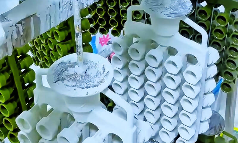
2. Шыбық жасау процесі: Қабық бетінің топографиясын басқаратын критикалық операциялық айнымалылар
Қабықпен қаптау операциясы дымқыл жабынға отқа төзімді құмды жағудан әлдеқайда көп.
Бұл керамикалық бөлшектердің суспензия ішінде қалай бекітілгенін анықтайтын шешуші процесс., , сорт, кептіруден кейін қабықтың ішкі беті қалай шығарылады, оқ атқан, және металл құю.
Енгізу шарты, бөлудің біркелкілігі, және сылақ бөлшектерінің тұрақтылығы қабықтың беткі қабатының микроскопиялық контурына және ақырында құйманың беткі қабатына тікелей әсер етеді..

Шыбық пен дымқыл бет қабатының арасындағы бөлшектердің өлшемі сәйкес келеді
Табысты жабынның бірінші принципі - отқа төзімді құмның бөлшектерінің мөлшері мен дымқыл бет қабатының қалыңдығы арасындағы дұрыс қатынасқа қол жеткізу..
Өлшемді шыбық бөлшектерінің әсері
Шыбық бөлшектері шамадан тыс өрескел болған кезде, олардың өлшемдері суспензия қабатының қалыңдығынан асып түседі.
Осы шарттарда, бөлшектер дымқыл жабынға еніп, балауыз үлгісінің бетіне тікелей жанасады.
Бұл құбылыс палаусыздандыру және күйдіруден кейін керамикалық қабықшада қалатын балауыз үлгісінде локализацияланған әсерлерді тудырады., сайып келгенде, қабықтың ішкі бетінде шығыңқы немесе бетінің бұзылуы ретінде пайда болады.
Ірі шыбық бөлшектері де болуы мүмкін:
- Жергілікті кернеулердің шоғырлану аймақтарын жасаңыз;
- Қаптау қалыңдығының ауытқуын тудырады;
- Металл ену ақауларының ықтималдығын арттырыңыз;
- Қабық беті жабынының кедір-бұдырлығын айтарлықтай арттырыңыз.
Шамадан тыс жұқа шыбық бөлшектерінің әсері
Керісінше, өте жұқа шыбықтың бөлшектері суспензия қабатының ішінде тығыз жиналады.
Бөлшекаралық қашықтықтың азаюы қабықтың өткізгіштігін төмендетеді және қабық бетіндегі көптеген ұсақ бөлшектердің контурын көрсетеді..
Болғандықтан:
- Беттік микропротрузиялар айқынырақ болады;
- Газ өткізгіштігі төмендейді;
- Газға байланысты құю ақауларының пайда болу қаупі артады;
- Бөлшектердің өлшемі кішірек болғанымен қабықтың беті кедір-бұдыр болады.
Бөлшектердің өлшемдерінің оңтайлы қатынасы
Өндірістің практикалық тәжірибесі ең тұрақты кірістіру жағдайына сылақ бөлшектерінің орташа өлшемі шамамен бақыланатын кезде қол жеткізілетінін көрсетті.:
50%– дымқыл бет қабатының қалыңдығының 67%.
Осы шарт бойынша:
- Әрбір бөлшектің шамамен жартысы суспензияға салынған;
- Қалған бөлігі жабын қабатының сыртында қалады;
- Құм бөлшектері балауыз үлгісіне енбейді және қабық бетінде толығымен ашылады.
Кәдімгі бет қабатының қалыңдығына арналған 0.3-0.5 мм, ұсынылатын сылақ өлшемі әдетте:
| Ылғал бет пальто қалыңдығы | Ұсынылатын сылақ өлшемі |
| 0.30 мм | 120– 140 тор |
| 0.40 мм | 100– 120 тор |
| 0.50 мм | 80– 100 тор |
Процесс уақыты: Critical Stucco қолданбасының терезесі
Өндірістік тәжірибеде сылақ төсеу мерзімі жиі бағаланбайды, бірақ ол бөлшектердің ену сапасы мен бетінің морфологиясына шешуші әсер етеді.
Мерзімінен бұрын шыбықты қолдану
Бояудан кейін бірден, суспензия жоғары сұйық болып қалады және құм бөлшектерін ұстап тұру үшін жеткілікті тұтқырлық әлі дамымаған.
Шыбықтарды тым ерте жағу нәтижеге әкелуі мүмкін:
- Бөлшектердің миграциясы және орын ауыстыруы;
- Бөлшектердің біркелкі емес таралуы;
- Құмның локализацияланған жиналуы;
- Дөрекі дөңес және толқындылықтың пайда болуы.
Алынған қабық беті жиі бір аймақтан екіншісіне айтарлықтай кедір-бұдырлық өзгерістерін көрсетеді.
Кешіктірілген сылақ қолданбасы
Егер сылақ төсеу шамадан тыс кешіктірілсе, суспензия бетінде ішінара гельдену немесе терінің түзілуі басталады.
Осы шарттарда:
- Құм бөлшектері жабынға дұрыс ене алмайды;
- Механикалық бекіту жеткіліксіз болады;
- Бетінде қалқымалы бөлшектер түзіледі.
Кейінгі снаряд жасау операциялары кезінде, бұл бос бекітілген бөлшектер жиі ажырайды, қабықтың кедір-бұдырлығын айтарлықтай арттыратын көптеген микроскопиялық шұңқырлар мен қуыстарды қалдырады.
Оңтайлы төсеу терезесі
Кәдімгі кремний-золды бетті бояу жүйелеріне арналған, ұсынылатын сылақ қолдану мерзімі:
30– жабыннан кейін 90 секунд.
Осы уақыт аралығында:
- Шламның тұтқырлығы тиісті деңгейге дейін өсті;
- Артық сұйықтық жоғалып кетті;
- Бөлшектерді тиімді енгізу үшін жеткілікті пластикалық қалады.
, Сорт, құм бөлшектері біркелкі бөлініп, мықтап бекітіледі, ең тегіс және ең дәйекті қабық бетін жасайды.
Шыбықтың сапасына әсер ететін қоршаған орта факторлары
Қабықпен қаптау кезінде қоршаған орта бөлшектердің ену тәртібін және қабық бетінің сапасын айтарлықтай өзгерте алады..
Барлық экологиялық айнымалылар арасында, құм ылғалдылығы жіне қоршаған ортаның салыстырмалы ылғалдылығы ең ықпалдылары болып табылады.
Шыбық құмының ылғалдылығы
Шыбық материалының ылғалдылық деңгейін төменде сақтау керек:
0.4%
Шамадан тыс ылғалдылық суспензияның локализацияланған аймақтарына суды енгізеді, ұнтақтың сұйыққа қатынасын өзгертіп, тұтқырлықтың күрт жоғарылауын тудырады.
Салдарына жатады:
- Қалқымалы құмның жиналуы;
- Бөлшектердің біркелкі емес таралуы;
- Әлсіз қабат аралық байланыс;
- Деламинация ақаулары.
Бұл ақаулар қабықтың құрылысы кезінде жасырын қалуы мүмкін, олар көбінесе палаусыздандыру және күйдіру кезінде айқын болады, олар қайда көрінеді:
- Беткі шұңқырлар;
- Тұрақты емес шығулар;
- Дөрекі аймақтар;
- Жергілікті қабықтың шашырауы.
Қоршаған ортаның салыстырмалы ылғалдылығы
Қабықпен қаптау жұмыстары үшін ұсынылатын қоршаған орта ылғалдылығы:
40%–60% RH
Төмен ылғалдылық жағдайлары
Ылғалдылық тым төмен болғанда:
- Жер үсті сулары тез буланады;
- Терінің мерзімінен бұрын пайда болуы;
- Құм бөлшектері жеткілікті түрде ене алмайды.
Нәтиже - бөлшектердің нашар бекітілуі және қабықтың кедір-бұдырының жоғарылауы.
Жоғары ылғалдылық жағдайлары
Ылғалдылық шамадан тыс жоғары болған кезде:
- Кептіру айтарлықтай баяулайды;
- Құм бөлшектері тартылыс күшінің әсерінен батып кете береді;
- Кейбір бөлшектер суспензия қабатына енеді.
Бұл шарттар түптеп келгенде өндіреді:
- Қабықтың тегіс емес беттері;
- Бөлшектердің отыру ақаулары;
- Кедір-бұдырлық мәндерінің жоғарылауы.
3. Үлгі бетінің жай-күйі және жабынды қолдану техникасы
Бет қабаты тікелей балауыз үлгісінің бетінде қалыптасады. Сондықтан, Үлгі бетінің сапасы және жабынды қолдану әдісі төмен кедір-бұдырлы жабынға қол жеткізу үшін негізгі алғышарттар болып табылады.
Үлгі бетінің кедір-бұдырлығын тасымалдау
Құю ережесі ретінде, өрнек бетінің кедір-бұдырлығы шамамен а шамасында қабықтың беткі қабатына ауысады 1:1 пропорция.
Балауыз үлгісінде сызаттар болса, шұңқырлар, ағын сызықтары, немесе басқа ақаулар, тіпті ең тегістеу үшін оңтайландырылған суспензия осы ауқымды кемшіліктерді толығымен толтыра алмайды.
Соңғы қабықтың кедір-бұдырлығы кем дегенде үлгідегідей жоғары болады.
Төмен кедір-бұдырлы жабындарға қойылатын талаптар:
| Параметр | Қажетті спецификация | Қанағаттантарлық |
| Үлгі құралының бетінің кедір-бұдырлығы | Ra ≤0,4 мкм | Жылтыратылған болат немесе алюминий құрал, шайыр немесе гипс емес. |
| Балауыз инъекциясының параметрлері | Оңтайландырылған (қысым, температура, тұру) | Ағын белгілерінің алдын алады, суық жабдықтар, және беттік тотығу. |
| Инъекциядан кейінгі өңдеу | Зең шығару қалдықтары мен микробқаларды кетіру үшін сүртіңіз немесе майсыздандырыңыз. | Контаминанттан туындаған ақауларды жояды. |
| Соңғы үлгінің кедір-бұдырлығы | Ra ≤0,8 мкм | Тікелей беру қабықтың қолайлы кедір-бұдырлығын қамтамасыз етеді. |
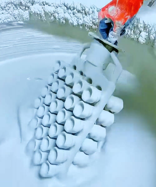
Қаптауды қолдану техникасы
Бет жабынының суспензиясын қолдану әдісі соңғы беттің кедір-бұдырлығына айтарлықтай әсер етеді.
Қолданудың негізгі үш әдісі – щетка, батыру, және құю — айқын беттік қасиеттерді береді:
| Техника | Артықшылықтары | Шектеулер | Әдеттегі кедір-бұдырлыққа қол жеткізілді (RA) |
| Щетка | Қол жеткізу қиын аймақтарды дәл бақылау; күрделі ішкі қуыстарға жақсы. | Қылқалам іздері жабынға қатып қалуы мүмкін; операторға тәуелді; шабан. | 1.6-3,2 мкм |
| Батыру | Біркелкі, біркелкі жабындар; жоғары өнімділік; оператордың минималды әсері. | Жеткілікті сұйық суспензияны қажет етеді; үлгі дизайны дренажға мүмкіндік беруі керек. | <1.6 мкм (ең жақсы) |
| Құю / бүрку | Үлкен немесе тұрақты емес үлгілер үшін қолайлы; жақсы қамту. | Мұқият бақыланбайтын болса, тамшылар мен ағын сызықтарын жасай алады. | 1.6-2,5 мкм |
Оңтайлы батыру параметрлері:
- Үлгіні алу жылдамдығы: Ең маңызды параметр. диапазонында алу жылдамдығы 10‑15 см/с тұрақты жасайды, біркелкі суспензия пленкасы.
Тым жылдам → жабынның шамадан тыс қалыңдығы және ағу; тым баяу → жабын тым жұқа және үзіліссіз. - Шламда тұру уақыты: 5‑Толық сулану үшін 15 секунд.
- Дренаж уақыты: Шығарғаннан кейін, 10‑20 секундқа шылау алдында артық суспензияның ағып кетуіне мүмкіндік беріңіз.
Суға батыру әдісі, дұрыс бақылау кезінде, ең төменгі және ең тұрақты кедір-бұдырлық мәндеріне қол жеткізеді.
Қылқалам кішкентай үшін батыруға сәйкес келеді, күрделі бөліктер, бірақ оператордың көбірек өзгергіштігін енгізеді.
4. Қолданбадан кейінгі өңдеу: Кептіру, Дезавакс, және Атыс
Бет жағын жағып, сылап болғаннан кейін де, келесі өңдеу қадамдары — кептіру, Дезавакс, және күйдіру — кедір-бұдырлық ақауларды енгізуі немесе күшейтуі мүмкін.
Ерте кезеңдерде пайда болған көптеген жасырын ақаулар осы термиялық-механикалық өңдеулер кезінде көрінеді..
Кептіру және емдеу
Кептіру процесі кремнеземді байланыстырғыштың гельденетін жері болып табылады. Коллоидты кремний диоксиді бөлшектері үздіксіз желіге біріктіріледі, отқа төзімді бөлшектерді орнында бекіту.
Бетінен судың булануын мұқият бақылау керек:
- Кептіру тым жылдам болса (Жоғары температура, күшті ауа ағыны): Беті кебеді және тері қалыптастырады, ал ішкі бөлігі ылғалды болып қалады.
Қапталған су кейінірек буланып кетеді, қабықтың бетінде шұңқырлар ретінде ашылатын көпіршіктер немесе жарықтар тудырады. - Кептіру тым баяу болса (төмен температура, Жоғары ылғалдылық): Қаптау шөгуі немесе шыбық шөгуі мүмкін, біркелкі емес текстураны жасау.
Оңтайлы кептіру шарттары: Жұмсақ, жақсы ауа айналымы бар біркелкі экспозиция, бірақ тікелей соқпау:
- Температура: 22‑25°C.
- Салыстырмалы ылғалдылық: 50‑70%.
- Кептіру уақыты: 4‑Бет пальто үшін 8 сағат, суспензияның құрамы мен қалыңдығына байланысты.
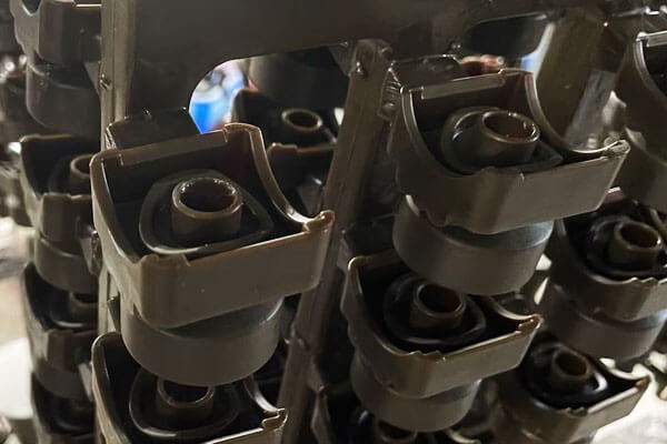
Дезавакс
Балауызды тазарту қадамы - балауыз үлгісін балқыту - үлгінің кеңеюі қабықтың ішкі бетін бұрмалауын болдырмау үшін бақыланатын қыздыру арқылы орындалуы керек..
Температураның жоғарылауы тым жылдам болса, балауыз керамикалық қабық сыйдыра алатындан көбірек кеңейеді.
Нәтижесінде жарылуы мүмкін ішкі қысым, дөңес, немесе бет жабындысын деформациялайды, соңғы құймада тұрақты бет ақауларын қалдыру.
Үздік тәжірибе: Бумен палаусыздандыруда (автоклав), дейін бу қысымын көтеріңіз 0.6 ішінде МПа 30 секунд.
Бұл жылдамдықты қамтамасыз етеді, ішінен біркелкі жылыту. Балауыз тез ериді және айтарлықтай термиялық кеңею пайда болмай тұрып ағып кетеді.
Бұл әдіс бет пальтосының бастапқы тегіс бетін сақтайды.
Оқ атқан (Агломерация)
Финал керамикалық қабықты күйдіру жоғары температурада қалдық көміртекті жағуға қызмет етеді, ұшпа ластаушы заттарды алып тастаңыз, және беріктік үшін отқа төзімді бөлшектерді күйдіріңіз.
Бетінің деградациясын болдырмау үшін күйдіру жағдайларын бақылау қажет:
- Жылдам қыздыру: Тұтқыр ыдырау газдары тым тез шығуы мүмкін, қабық бетінде шұңқырлы кратерлерді жасау.
- Шамадан тыс күйдіру температурасы: Шамадан тыс агломерация шыны тәрізді фазаның пайда болуы мен ағынын тудырады, толқынды жасау, бұрмаланған бет.
Кремний-золь-циркон беттік жабындары үшін оңтайлы күйдіру кестесі:
- Температураны ұстаңыз: 950-1050°C.
- Уақытты ұстаңыз: 2- 3 сағат.
- Рампаның жылдамдығы: 4‑6°C/мин (газдың шығуын қамтамасыз ету үшін біртіндеп).
Осы ауқымда, қабық шамадан тыс балқыған ағынсыз құю үшін жеткілікті беріктікке ие болады, ал бет пальто тегістігін сақтайды, алдыңғы қадамдар кезінде қалыптасқан тығыз құрылым.
Кедір-бұдыр тұрақты төмен болып қалады (Ra ≤1,6 мкм) дұрыс атылған кезде.
5. Практикалық сапаны басқару және процесс ішіндегі мониторинг
Тұрақты төмен кедір-бұдырлыққа қол жеткізу үшін жүйелі бақылау мен бақылау қажет снаряд жасау өңдеу. Ұсынылатын процестегі тексерулер мыналарды қамтиды:
| Тексеру нүктесі | Параметр бақыланады | Тест әдісі | Қолайлы диапазон |
| Шламдар партиясы | Шынтақ қ (Зан кесе) | Жоқ. 4 кесе | 35‑45 секунд |
| Шламдар партиясы | P/L қатынасы | Гравиметриялық | 3.2‑3.5 : 1 |
| Ұнтақ партиясы | Бөлшек өлшемдерінің таралуы | Лазерлік дифракция | Бимодальды; <1% >45 мкм |
| Шұңғыл | Ылғалдылық | Кептіру кезіндегі жоғалту | <0.4% |
| Қоршаған орта | Температура / ылғалдық | гигрометр | 22‑25°C / 40‑60% RH |
| Қаптау операциясы | Шығу жылдамдығы | Таймер / калибрленген қондырғы | 10‑15 см/с |
| Қаптау операциясы | Дефифицирлеу профилі | Қысым уақытын тіркеуші | 0.6 30-шы жылдардағы МПа |
| Оқ атқан | Пеш профилі | Термопара жазбасы | 950-1050°C, 2- 3 сағат |
Процесс барысындағы визуалды тексеру: 10 × ұлғайтқышты пайдаланып, жабынмен қапталған жабындарды кезеңді түрде тексеру шыбықтың шығуының алғашқы белгілерін анықтауға болады., жиналу, немесе толық емес қамту.
Портативті беттік профильометр (байланыс немесе байланыссыз) кедір-бұдырлық мақсаттарының орындалғанын тексеру үшін таңдалған құрбандық үлгілерінде пайдалануға болады.
6. Бет қабатының кедір-бұдырлығын құю бетінің соңғы өнімділігіне аудару
Қабық беті жабынының кедір-бұдырының маңыздылығы қабық жасау кезеңінен әлдеқайда жоғары.
Инвестициялық құюда, керамикалық пальто ретінде қызмет етеді соңғы құрамдас бетінің теріс репликасы, оның микротопографиясы қатаю кезінде құймаға тікелей дерлік ауысатынын білдіреді.
, Сорт, тіпті қабықтың кедір-бұдырлығындағы шамалы ауытқулар да функционалдық өнімділікке өлшенетін әсер етуі мүмкін, Қызмет көрсету мерзімі, және дайын құрамдас бөліктің коммерциялық құны.
Дәлдігі жоғары құймалар үшін, бет қабатының кедір-бұдырлығын бақылау тек косметикалық талап емес, ол компоненттің механикалық және жұмыс тәртібіне әсер ететін маңызды инженерлік параметр болып табылады..
Беттік репликация механизмі
Құю кезінде, балқытылған металл керамикалық қабық бетіндегі әрбір микроскопиялық ойыстар мен шығыңқы жерлерді толтырады.
Елеуленгеннен кейін, құйма осы бет ерекшеліктерін керемет дәлдікпен шығарады.
сияқты факторлар болса да:
- Қорытпаның шөгуі,
- Металлдың өтімділігі,
- Қалып-металл реакциялары,
- Құмның жануы,
соңғы бет құрылымын сәл өзгерте алады, қабықтың беткі қабаты құйма кедір-бұдырлығын реттейтін басым фактор болып қала береді.
Инвестициялық құю процестерінің көпшілігінде, қабық пен құйма арасындағы кедір-бұдырдың беріліс коэффициенті:
1:1 қарай 1:1.3
Бұл Ra мәні бар қабық бетін жабу дегенді білдіреді 1.6 мкм әдетте шамамен 1,8–2,0 мкм құйма бетінің кедір-бұдырлығын тудырады.
Механикалық өнімділікке әсері
Шаршауға төзімділік
Беткейлік бұзылулар микроскопиялық ойықтар мен кернеу көтергіштер ретінде әрекет етеді. Циклдік жүктеме кезінде, бұл аймақтар жарықшақтарды бастау үшін қолайлы орындарға айналады.
Тегіс құйма беті ұсынады:
- Төменгі стресс концентрациясының факторлары;
- Жарықшалардың нуклеациялану орындарының азаюы;
- Ұзақ шаршау өмірі;
- Динамикалық жүктеме кезінде сенімділік жақсарды.
Бұл әсіресе маңызды:
- Турбина пышақтары;
- Әуе кемесінің құрылымдық компоненттері;
- Автокөлік қозғалтқышының бөлшектері;
- Жоғары жылдамдықты айналмалы жабдық.
Зерттеулер Ra-дан беттің кедір-бұдырлығын азайтуды көрсетті 4.0 мкм дейін Ra 2.0 мкм шаршау өмірін ұзарта алады 20% кейбір жоғары берік қорытпаларда.
Коррозияға төзімділік
Беттік морфология коррозияға қатты әсер етеді.
Кедір-бұдыр беттер бар:
- Алқаптар мен ойықтар;
- Электролиттің тоқырау аймақтары;
- Микрогальваникалық жасушалар.
Бұл мүмкіндіктер жылдамдатады:
- Коррозия;
- Жарық коррозиясы;
- Кернеу-коррозиялық крекинг.
Тот баспайтын болаттан жасалған медициналық имплантаттар мен химиялық өңдеу компоненттері үшін, тегіс құйма беті ұзақ мерзімді коррозияға төзімділікті және биоүйлесімділікті айтарлықтай жақсартады.
Wear Performance
Бетінің бастапқы күйі үйкеліс пен тозу механизмдеріне тікелей әсер етеді.
Кедір-бұдыр беті әдетте әкеледі:
- Жоғары үйкеліс коэффициенттері;
- Абразивті тозудың жоғарылауы;
- Материалды тезірек жою;
- Жылудың көп пайда болуы.
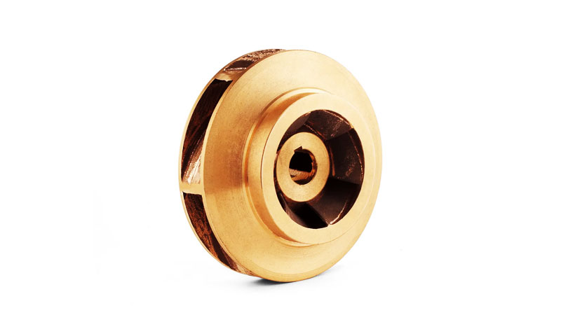
Сияқты компоненттер:
- Сорғы саппелттері;
- Клапанның денелері;
- Гидравликалық компоненттер;
- Жылжымалы механикалық бөлшектер,
төменгі бетінің кедір-бұдырынан айтарлықтай пайда көреді.
Сұйықтықтың динамикалық тиімділігіне әсері
Ағынды өңдеу жабдықтарында, бетінің кедір-бұдыры сұйықтықтың әрекетіне тікелей әсер етеді.
Микроскопиялық беттік шығыңқылар шекаралық қабатты бұзады және турбуленттілігін арттырады, апарады:
- Үйкеліс жоғалтулары жоғары;
- Ағын тиімділігінің төмендеуі;
- Энергияны тұтынудың жоғарылауы;
- Үлкен қысымның төмендеуі.
Бұл құбылыс әсіресе маңызды:
- Турбина пышақтары;
- Компрессорлық компоненттер;
- Сорғы саппелттері;
- Аэроғарыштық ағын арналары.
Дәл турбиналық қолданбалар үшін, тіпті бетінің кедір-бұдырының аздап төмендеуі аэродинамикалық тиімділікті арттырып, жабдықтың қызмет ету мерзімі ішінде пайдалану шығындарын азайтады.
Қаптау мен беттік өңдеуге әсері
Көптеген инвестициялық құюлар сияқты қосалқы операцияларды қажет етеді:
- Электроплицей;
- Анодтық;
- PVD жабыны;
- Термиялық бүрку;
- Сурет.
Бетінің шамадан тыс кедір-бұдыры себеп болуы мүмкін:
- Қаптаманың біркелкі емес қалыңдығы;
- Қаптаманың нашар адгезиясы;
- Локализацияланған ақаулар;
- Аяқтау шығындарының жоғарылауы.
Құйылған беттері жоғары құймалар шығару арқылы, өндірушілер бетті өңдеуден бұрын қажет жылтырату және өңдеу көлемін айтарлықтай азайта алады.
Өлшемдік дәлдік және өңдеуге рұқсат
Бетінің кедір-бұдырлығы өлшемді басқаруға да әсер етеді.
Дөрекі құю беті әдетте талап етеді:
- Көбірек өңдеуге рұқсат;
- Қосымша ұнтақтау операциялары;
- Кеңірек өңдеу процедуралары.
Бұл артады:
- Өндіріс құны;
- Өндіріс циклінің уақыты;
- Материалдық қалдықтар.
Керісінше, Кедір-бұдыры төмен құймалар көбінесе желіге жақын пішінді қолданбаларда қолданылуы мүмкін, инвестиция құюдың экономикалық артықшылықтарын барынша арттыру.
Эстетикалық және коммерциялық құндылық
Сыртқы түрі маңызды өнімдер үшін, бетті өңдеу маңызды сапа көрсеткішіне айналады.
Мысалдарға жатады:
- Медициналық импланттар;
- Тұрмыстық электроника компоненттері;
- Сәнді жабдық;
- Металлдан жасалған сәндік бұйымдар;
- Премиум автомобиль бөлшектері.
Тегіс бет береді:
- Жақсырақ көрнекі көрініс;
- Жақсартылған қабылданатын сапа;
- Жақсартылған тұтынушылардың қанағаттанушылығы;
- Өнімнің жоғары құны.
Көптеген жағдайларда, құйма бетінің әрлеуі нарықтағы қабылдауды тікелей анықтайды.
Бет қабатының кедір-бұдырлығы мен құйма бетінің сапасы арасындағы корреляция
Өндірістік тәжірибе мен тәжірибелік зерттеулер қаптаманың кедір-бұдырлығы мен құйма бетінің әрлеуі арасында айқын байланыс орнатты.
| Бет қабатының кедір-бұдырлығы (RA, мкм) | Құюдың әдеттегі кедір-бұдырлығы (RA, мкм) | Типтік қосымшалар |
| ≤ 1.6 | ≤ 2.0 | Аэроғарыш компоненттері, Медициналық импланттар, Турбина пышақтары, Жоғары сапалы автомобиль бөлшектері |
| 1.6-3.2 | 2.0-4.0 | Өнеркәсіптік клапандар, сорғылар, дәлме-дәл машиналар, Гидравликалық компоненттер |
| > 3.2 | > 4.0 | Құрылыс жабдықтары, Ауыр машиналар, жалпы инженерлік құймалар |
7. Қорытынды
Инвестициялық құю қабықшаларының бетінің кедір-бұдырлығы толық технологиялық көп факторлы біріктіру механизмімен бақыланады., жабатын суспензия материалының дизайны, сылақпен жұмыс істеу сипаттамалары, балауыз үлгісін алдын ала өңдеу, жабу техникасы, және өңдеуден кейінгі термохимиялық процестер.
Осы нүктелердің әрқайсысында бақылауға инвестициялау қосымша пайда әкеледі: Әрбір оңтайландырылған қадам беттің соңғы сапасына ықпал етеді, ол мұндай бақылаусыз жасалған қабықшадан гөрі жұқарақ болуы мүмкін..
Дәлдік инженерия — аэроғарыштық талаптарды қанағаттандыруға ұмтылатын құю зауыттары үшін, медициналық, өнімділігі жоғары автомобиль — төмен жабынның кедір-бұдырына ұмтылу қосымша сапа бағдарламасы емес.; бұл стратегиялық бәсекелестік императив.