1. Uvod
Učinkovita kontrola tekućine ovisi o odabiru pravog ventila za posao. Stoga, inženjeri se oslanjaju na tablice usporedbe veličina ventila za prevođenje između različitih standarda, usporediti dimenzionalne podatke, i provjerite kompatibilnost.
U ovom odjeljku, pojašnjavamo opseg članka, naglasiti zašto je važna točna veličina ventila, i definirati što je usporedna tablica veličine ventila—i zašto se pokazala tako korisnom u svakodnevnoj praksi.
- Svrha i opseg: Cilj nam je opremiti proces, mehanički, i inženjeri cjevovoda s opsežnim vodičem za izradu i korištenje usporednih tablica veličine ventila.
- Važnost točnog dimenzioniranja: Ventili pogrešne veličine mogu uzrokovati do a 15% pad učinkovitosti procesa, dovesti do preranog trošenja, ili čak izazvati kvarove sustava. Za razliku od, pravilno dimenzionirani ventili optimiziraju protok, smanjiti potrošnju energije, i produžiti vijek trajanja opreme.
- Pregled usporednih tablica: U svojoj srži, tablica za usporedbu veličine ventila usklađuje nazivnu veličinu cijevi (NPS) ili Nazivni promjer (Dn) oznake sa stvarnim promjerima provrta, dimenzije licem u lice, detalji prirubnice, i povezani parametri.
Čineći tako, omogućuje brzo unakrsno referenciranje preko ANSI-ja, IZ, On, ISO, i drugim standardima.
2. Osnove dimenzioniranja ventila
Prije oblikovanja ili tumačenja usporedne tablice, treba shvatiti osnovne koncepte dimenzioniranja.
Ispod, uspoređujemo nominalne i stvarne veličine, identificirati kritične dimenzionalne parametre, i objasnite kako ti čimbenici utječu na protok i izvedbu.
Nazivna veličina cijevi (NPS) vs. Stvarni provrt (ID)
- NPS označava standardiziranu oznaku (Npr., NPS 4), ali to čini ne jednak unutarnjem promjeru.
- Stvarni provrt (ID) razlikuje se ovisno o proizvođaču i standardu: na primjer, NPS 4 obično ima ID od 4.026 u (102.3 mm) u ANSI ventilima, ali se mogu razlikovati prema DIN ili JIS specifikacijama.
Ključni dimenzionalni parametri
- Licem u lice (F2F): Udaljenost između krajeva ventila—kritična za raspored cjevovoda.
- Od kraja do kraja (E2e): Sličan F2F, ali se ponekad koristi za ventile s pločicama ili ušice.
- Dimenzije prirubnice: Vanjski promjer (OD), promjer kruga vijka (BCD), broj i veličina rupa za vijke.
Utjecaj na protok i izvedbu
Dimenzioniranje ventila uvelike utječe na pad tlaka (ΔP) i koeficijent protoka (Životopis).
Na primjer, Povećanje veličine ventila za jedan NPS može povećati Cv za otprilike 20-25%, čime se smanjuju gubici energije u aplikacijama s velikim protokom.
3. Međunarodni i industrijski standardi
Globalne operacije zahtijevaju besprijekornu interoperabilnost. Tako, inženjeri se moraju kretati kroz više standardnih tijela:
| Standardno tijelo | Ključni dokumenti | Klase tlaka |
|---|---|---|
| ANSI/ASME (SAD) | B16.10, B16.5 | 150#, 300#, 600#, itd. |
| TVOJ JEDAN (Europa) | U 558, PN razredi | PN 6, PN 10, PN 16, PN 40 |
| On (Japan) | B2239 (F2F), B2002 (prirubnice) | 5K, 10K, 16K, 20K |
| ISO (Globalan) | 5752, 7005 | Niz 1, Niz 2 |
4. Tablica za usporedbu veličina zasuna
Referirani standardi: ASME B16.10, ASME B16.5 (Klasa 150), U 558, U 1092-1 (PN16)
Tipa ventila: Prirubnica, Zasun s punim otvorom
Pretpostavljeni materijal: Ugljični čelik (WCB), Dizajn uzdižuće stabljike
| NPS (u) | Dn (mm) | Stvarni provrt (ID, mm) | Licem u lice (mm) | Prirubnica OD (mm) | Krug vijka Ø (mm) | Ne. od vijaka | Otvor za vijak Ø (mm) |
|---|---|---|---|---|---|---|---|
| 2 | 50 | 51 | 178 | 152 | 120.5 | 4 | 19 |
| 2½ | 65 | 64 | 190 | 178 | 139.7 | 4 | 19 |
| 3 | 80 | 76 | 203 | 190 | 152.4 | 4 | 19 |
| 4 | 100 | 102 | 229 | 229 | 190.5 | 8 | 19 |
| 5 | 125 | 127 | 254 | 254 | 216 | 8 | 22 |
| 6 | 150 | 152 | 267 | 279 | 241.3 | 8 | 22 |
| 8 | 200 | 203 | 292 | 343 | 298.5 | 8 | 22 |
| 10 | 250 | 254 | 330 | 406 | 362 | 12 | 25 |
| 12 | 300 | 305 | 356 | 483 | 431.8 | 12 | 25 |
| 14 | 350 | 337 | 381 | 533 | 476.3 | 12 | 29 |
| 16 | 400 | 387 | 406 | 597 | 539.8 | 16 | 29 |
| 18 | 450 | 438 | 432 | 635 | 577.9 | 16 | 32 |
| 20 | 500 | 489 | 457 | 699 | 635 | 20 | 32 |
| 24 | 600 | 591 | 508 | 813 | 749.3 | 20 | 35 |
Bilješke:
- Stvarni provrt (ID) mogu malo varirati ovisno o proizvođaču i stilu opreme; vrijednosti su tipične za dizajn s punim priključkom.
- Licem u lice vrijednosti slijede ASME B16.10 ili EN 558 Niz 1.
- Prirubnica OD, Krug vijaka, i Dimenzije vijaka slijedite klasu ASME B16.5 150 / U 1092-1 PN16 prema potrebi.
- Sve dimenzije su unutra milimetara osim ako nije drugačije navedeno.
- Dizajn ventila po narudžbi ili više klase tlaka (Klasa 300, PN25) će zahtijevati različite dimenzije prirubnice i tijela.
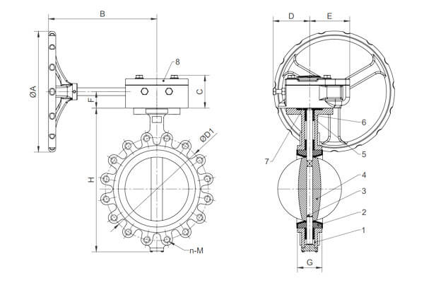
5. Tablica za usporedbu veličina leptir ventila
Tipa ventila: Leptir ventil s mekom brtvom u obliku pločica
Standardi: U 558 Niz 20 (Licem u lice), U 1092-1 (Prirubnica), ASME B16.5 klasa 150 Prirubnice
Ocjena pritiska: Pn10 / PN16 / ANSI klasa 150
| Dn (mm) | NPS (u) | Licem u lice (mm) | Vanjski promjer prirubnice (OD, mm) | Promjer kruga vijka (BCD, mm) | Broj rupa za vijke | Promjer rupe za vijak (mm) |
|---|---|---|---|---|---|---|
| 50 | 2 | 108 | 165 | 125 | 4 | 18 |
| 65 | 2½ | 114 | 185 | 145 | 4 | 18 |
| 80 | 3 | 127 | 200 | 160 | 8 | 18 |
| 100 | 4 | 140 | 220 | 180 | 8 | 18 |
| 125 | 5 | 152 | 250 | 210 | 8 | 18 |
| 150 | 6 | 165 | 285 | 240 | 8 | 22 |
| 200 | 8 | 191 | 340 | 295 | 8 | 22 |
| 250 | 10 | 216 | 395 | 350 | 12 | 22 |
| 300 | 12 | 241 | 445 | 400 | 12 | 22 |
| 350 | 14 | 267 | 505 | 460 | 16 | 22 |
| 400 | 16 | 292 | 565 | 515 | 16 | 26 |
| 450 | 18 | 318 | 620 | 565 | 20 | 26 |
| 500 | 20 | 343 | 670 | 620 | 20 | 26 |
| 600 | 24 | 394 | 780 | 725 | 20 | 30 |
Dodatne napomene:
- Licem u lice dimenzije za EN 558 Niz 20 dizajn pločice osigurava kompatibilnost s prirubnicama s oznakom PN10/PN16 ili ANSI klase 150.
- Dimenzije prirubnice (OD, krug vijaka, rupe za vijke) u skladu s EN 1092-1 ili ASME B16.5 kako bi se osigurala pravilna ugradnja između prirubnica cijevi.
- Veličina i broj otvora za vijke odgovaraju klasi i veličini prirubnice kako bi se održao integritet pritiska.
- Leptir ventili s mekom brtvom koriste elastomerne obloge (EPDM, NBR, Viton) a poželjni su za vodu, HVAC, i lake kemijske usluge.
6. Tablica za usporedbu veličina leptir ventila s mekom brtvom prirubnice
Tipa ventila: Leptir ventil s mekom brtvom s prirubnicom
Standardi: U 558 Niz 20 (Licem u lice), U 1092-1 (Prirubnice PN10/16), ASME B16.5 klasa 150 Prirubnice
Klasa tlaka: Pn10 / lim16 / ANSI klasa 150
| Dn (mm) | NPS (u) | Licem u lice (mm) | Vanjski promjer prirubnice (mm) | Promjer kruga vijka (mm) | Broj rupa za vijke | Promjer rupe za vijak (mm) |
|---|---|---|---|---|---|---|
| 50 | 2 | 140 | 165 | 125 | 4 | 18 |
| 65 | 2½ | 152 | 185 | 145 | 4 | 18 |
| 80 | 3 | 165 | 200 | 160 | 8 | 18 |
| 100 | 4 | 178 | 220 | 180 | 8 | 18 |
| 125 | 5 | 191 | 250 | 210 | 8 | 18 |
| 150 | 6 | 203 | 285 | 240 | 8 | 22 |
| 200 | 8 | 229 | 340 | 295 | 8 | 22 |
| 250 | 10 | 254 | 395 | 350 | 12 | 22 |
| 300 | 12 | 279 | 445 | 400 | 12 | 22 |
| 350 | 14 | 305 | 505 | 460 | 16 | 22 |
| 400 | 16 | 330 | 565 | 515 | 16 | 26 |
| 450 | 18 | 356 | 620 | 565 | 20 | 26 |
| 500 | 20 | 381 | 670 | 620 | 20 | 26 |
| 600 | 24 | 432 | 780 | 725 | 20 | 30 |
Bilješke:
- Licem u lice dimenzija odgovara EN 558 Niz 20 prirubnički leptir ventil standard, pogodan za ugradnju između prirubnica ocijenjenih PN10/PN16 ili ANSI klase 150.
- Prirubnica OD, Promjer kruga vijka, Količina i veličina rupa za vijke u skladu s EN 1092-1 i ASME B16.5 kako bi se osigurala kompatibilnost sa standardnim prirubnicama cijevi.
- Meka brtva obično koristi elastomere kao što je EPDM, NBR, zlatni Viton, pruža izvrsno brtvljenje za vodu, zrak, i lake kemijske primjene.
- Prirubnički leptir ventili omogućuju jednostavno uklanjanje/zamjenu bez ometanja prirubnica cjevovoda.
7. Dimenzije leptir ventila prema EN standardu
Standard: U 558 (Licem u lice) & U 1092-1 (Prirubnica)
Tipa ventila: Vafer/s prirubnicom, Mekana brtva
Klasa tlaka: Pn10 / PN16
| Dn (mm) | Dužina licem u lice (mm) | Vanjski promjer prirubnice (mm) | Promjer kruga vijka (mm) | Broj rupa za vijke | Promjer rupe za vijak (mm) |
|---|---|---|---|---|---|
| 50 | 108 | 165 | 125 | 4 | 18 |
| 65 | 114 | 185 | 145 | 4 | 18 |
| 80 | 127 | 200 | 160 | 8 | 18 |
| 100 | 140 | 220 | 180 | 8 | 18 |
| 125 | 152 | 250 | 210 | 8 | 18 |
| 150 | 165 | 285 | 240 | 8 | 22 |
| 200 | 191 | 340 | 295 | 8 | 22 |
| 250 | 216 | 395 | 350 | 12 | 22 |
| 300 | 241 | 445 | 400 | 12 | 22 |
| 350 | 267 | 505 | 460 | 16 | 22 |
| 400 | 292 | 565 | 515 | 16 | 26 |
| 450 | 318 | 620 | 565 | 20 | 26 |
| 500 | 343 | 670 | 620 | 20 | 26 |
| 600 | 394 | 780 | 725 | 20 | 30 |
Obrazloženje:
- Dužina licem u lice: Za EN 558 Niz 20, odnosi se na leptiraste ventile s pločicama i ušicama.
- Vanjski promjer prirubnice, Promjer kruga vijka, Broj/veličina rupa za vijke: Na temelju EN 1092-1 standardi prirubnica za klase tlaka PN10 i PN16.
- Ove dimenzije osiguravaju kompatibilnost s odgovarajućim prirubnicama cijevi i olakšavaju instalaciju.
- A uzorak otvora za vijke osigurava odgovarajuću mehaničku čvrstoću i cjelovitost brtvljenja.
8. Tablica standarda veličine kuglastih ventila
ANSI dimenzije odražavaju američke standarde; EN dimenzije odražavaju europske standarde.
Referirani standardi: Na temelju ANSI / ASME standardi
Referirani standardi:
- ASME B16.10 – Dimenzije licem u lice i s kraja na kraj
- ASME B16.5 – Prirubnički spojevi (za klase tlaka 150–2500)
- ASME B16.34 – Dizajn ventila, materijal, i ocjene tlak-temperatura
| Dn (mm) | NPS (u) | Licem u lice (mm) ANSI/ASME B16.10 | Prirubnica OD (mm) ANSI B16.5 klasa 150 | Promjer kruga vijka (mm) ANSI B16.5 | Broj vijaka | Promjer rupe za vijak (mm) | Licem u lice (mm) U 558 | Prirubnica OD (mm) U 1092-1 PN16 | Promjer kruga vijka (mm) U 1092-1 | Broj vijaka EN 1092-1 | Promjer rupe za vijak (mm) U 1092-1 |
|---|---|---|---|---|---|---|---|---|---|---|---|
| 50 | 2 | 152 | 165 | 125 | 4 | 18 | 140 | 185 | 145 | 4 | 18 |
| 65 | 2½ | 165 | 190 | 145 | 4 | 18 | 152 | 200 | 160 | 8 | 18 |
| 80 | 3 | 178 | 215 | 160 | 8 | 18 | 165 | 220 | 180 | 8 | 18 |
| 100 | 4 | 190 | 254 | 180 | 8 | 18 | 178 | 250 | 210 | 8 | 18 |
| 125 | 5 | 216 | 279 | 210 | 8 | 22 | 191 | 285 | 240 | 8 | 18 |
| 150 | 6 | 241 | 324 | 241 | 8 | 22 | 216 | 320 | 295 | 8 | 22 |
| 200 | 8 | 292 | 406 | 362 | 8 | 22 | 267 | 405 | 355 | 8 | 22 |
| 250 | 10 | 330 | 483 | 432 | 12 | 25 | 292 | 460 | 410 | 12 | 22 |
| 300 | 12 | 356 | 559 | 483 | 12 | 25 | 318 | 515 | 460 | 12 | 22 |
| 350 | 14 | 394 | 597 | 539 | 16 | 29 | 343 | 565 | 515 | 16 | 22 |
| 400 | 16 | 432 | 673 | 595 | 16 | 29 | 368 | 620 | 565 | 16 | 26 |
| 450 | 18 | 483 | 698 | 622 | 20 | 32 | 394 | 675 | 615 | 20 | 26 |
| 500 | 20 | 508 | 749 | 673 | 20 | 32 | 419 | 730 | 670 | 20 | 26 |
| 600 | 24 | 584 | 864 | 787 | 20 | 35 | 483 | 840 | 780 | 20 | 30 |
Obrazloženje:
- Licem u lice: Duljina između krajeva ventila, kritičan za postavljanje cijevi.
- Vanjski promjer prirubnice (OD) i Promjer kruga vijka odrediti kompatibilnost prirubnice.
- Broj i veličina vijaka ovise o veličini prirubnice i nazivnom tlaku.
- Razlike mogu zahtijevati adaptere ili prilagođene prirubnice u međunarodnim projektima.
9. Multi-perspektivna analiza
Točnost dimenzije
Uske tolerancije (±1% na provrt, ±2 mm licem u lice) smanjiti pogrešno poravnanje tijekom instalacije.
Naduti, točne dimenzije osiguravaju pravilnu kompresiju brtve, očuvanje cjelovitosti brtve pod pritiscima do 250 bar.
Kompatibilnost materijala
Odabir materijala—ugljični čelik, nehrđajući čelik, ili specijalizirane legure—često mijenja debljinu stjenke i ukupne dimenzije.
Na primjer, mogu se pojaviti nehrđajući ventili 5% deblje stijenke kako bi se omogućile dopuštenja za koroziju, čime se malo mijenjaju nominalne dimenzije F2F.
Ocjene tlaka i temperature
Oznake kućišta ventila moraju biti usklađene s ocjenama prirubnice.
Kao primjer, ANSI 300# ventil (maksimalni radni pritisak 74 bar na 100 ° C) parovi sa 300# prirubnice s većim krugovima vijaka (216 mm u odnosu na. 184 mm za 150#), što zahtijeva poseban stupac tablice za klasu tlaka.
Razmatranja specifična za primjenu
- Petrokemija vs. tretman vode vs. HVAC: Agresivni mediji u petrokemijskim postrojenjima često zahtijevaju posebne legure i strože tolerancije; za razliku od, HVAC ventili mogu slijediti labaviji ANSI 150# naočale.
- Sanitarni (trostruka stezaljka) vs. industrijske prirubnice: Priključci s tri stezaljke koriste sučeono zavarene ili spojne krajnje spojeve i obično u potpunosti odstupaju od ANSI/DIN uzoraka vijaka,
što jamči specijalizirani mini-stol.
Troškovi i implikacije na lanac opskrbe
Standardni ventili (90% tržišne potražnje) uživajte u kraćim rokovima isporuke (2– 4 tjedna) i niži jedinični trošak.
Međutim, prilagođene veličine ili posebni materijali mogu produljiti vrijeme isporuke na 12-16 tjedana i povećati troškove za 30-50%.
Stoga, čarape popularne veličine (Npr., NPS 2, 4, 6) smanjuje rizik od zastoja i smanjuje troškove nošenja zaliha.
10. Zaključak
Točno dimenzioniranje ventila i prevođenje između standarda igra ključnu ulogu u očuvanju pouzdanosti postrojenja, optimiziranje performansi, i kontroliranje troškova.
Izgradnjom dobro organizirane tablice za usporedbu veličina ventila—zajedno s bitnim dimenzijama, klase tlaka, i materijalne bilješke,
Inženjerski timovi mogu pojednostaviti pregled dizajna, ubrzati nabavu, i minimizirati pogreške prilikom instalacije.
Konačno, ulaganje vremena u izgradnju i održavanje ovih tablica donosi dividende u smanjenom vremenu zastoja, poboljšana sigurnost, i poboljšana operativna učinkovitost.
Različiti proizvođači ventila mogu imati male varijacije na temelju standardnih dimenzija.
Pri izboru ventila u praksi, bitno je uzeti u obzir specifične zahtjeve projekta, parametri cjevovodnog sustava, i specifikacije proizvoda koje je dostavio proizvođač kako bi se osigurao točan odabir i ispravna ugradnja.
OVAJ je savršen izbor za vaše potrebe za proizvodnjom ako vam treba visokokvalitetna Komponente ventila.

