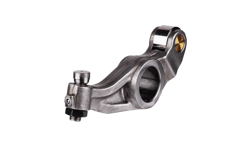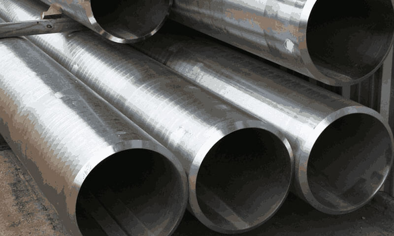

У машынабуд, незлічоная колькасць кампанентаў можа выглядаць па-рознаму па форме і функцыях, але многія з іх можна класіфікаваць па абмежаванай колькасці тыповых структурных формаў.
Сярод найбольш прадстаўнічых з'яўляюцца шахты, рукавы, дапрацоўкі, перадачы, поршні, і шатуны.
Задача пры апрацоўцы гэтых дэталяў заключаецца не проста ў выбары рэжучага інструмента або станка.
Надзейны план працэсу павінен каардынаваць пусты выбар, дызайн даты, паслядоўнасць апрацоўкі, размеркаванне дапаможнікаў, тэрмічная апрацоўка, канструкцыя свяцільні, параметры рэзкі, мерная інспекцыя, і аб'ём вытворчасці.
У гэтым артыкуле даецца сістэматычны агляд метадаў апрацоўкі, тыпавыя тэхналагічныя маршруты, асноўныя тэхнічныя патрабаванні, і агульныя вытворчыя праблемы, звязаныя з гэтымі шасцю тыповымі механічнымі часткамі.
1. Апрацоўка дэталяў вала: Тэст ротарнай апрацоўкі кампанентаў
Дэталі вала з'яўляюцца аднымі з найбольш рэпрэзентатыўных кампанентаў у машынабудаванні.
Іх асноўныя функцыі - падтрымліваць элементы, якія верцяцца, перадаць крутоўны момант, перадаць магутнасць, і падтрымліваць адноснае становішча падшыпнікаў, перадачы, шківы, муфты, і іншыя кампаненты трансмісіі.
Якасць вала вызначаецца спалучэннем дакладнасці памераў, дакладнасць формы, пазіцыйная дакладнасць, і цэласнасць паверхні.
Для адносна простых невялікіх валаў, круглы пруток часта эканамічны, таму што пачатковая геаметрыя ўжо набліжаецца да канчатковай цыліндрычнай формы.
Для высокатрывалых або моцна нагружаных валаў, коўка можа забяспечыць лепшае выкарыстанне матэрыялу і больш спрыяльныя механічныя ўласцівасці. Для вялікіх або вельмі складаных валаў могуць спатрэбіцца спецыяльныя працэсы ліцця або кавання.

Тыповы працэс апрацоўкі вала
Агульны маршрут апрацоўкі вала можна выказаць як:
Падрыхтоўка нарыхтоўкі → абліцоўванне і цэнтральнае свідраванне → чарнавая апрацоўка → тэрмічная апрацоўка → паўаздабленне → другасная апрацоўка → фінішная апрацоўка → шліфаванне або суперфінішная апрацоўка → канчатковая праверка
Дакладная паслядоўнасць змяняецца ў залежнасці ад геаметрыі вала і матэрыялу, але стабільнасць даных і паслядоўнасць працэсаў застаюцца цэнтральнымі меркаваннямі.
Для многіх прэцызійных валаў, цэнтральныя адтуліны ўсталёўваюцца на ранняй стадыі, а затым выкарыстоўваюцца ў якасці эталонных баз для наступнай апрацоўкі.
Апрацоўка паміж цэнтрамі дазваляе ствараць розныя знешнія цыліндрычныя паверхні адносна агульнай восі, што асабліва карысна, калі кааксіяльнасць мае вырашальнае значэнне.
Чаму паслядоўнасць працэсаў мае значэнне
Галоўным прынцыпам апрацоўкі вала з'яўляецца выкананне значнага выдалення матэрыялу, пакуль нарыхтоўка ўсё яшчэ мае дастатковую структурную калянасць.
Напрыклад, чарнавая апрацоўка вялікіх дыяметраў звычайна выконваецца перад шырокай апрацоўкай меншых дыяметраў.
Калі занадта шмат матэрыялу выдаляецца з тонкай вобласці на ранняй стадыі, мясцовая калянасць памяншаецца, і вал становіцца больш успрымальным да:
Прагін → вібрацыя → памылка памеру → геаметрычнае адхіленне
Тэрмічная апрацоўка таксама павінна быць інтэграваная ў працэс працэсу. Калі патрабуецца загартоўка або гартаванне, павінен быць захаваны дастатковы прыпуск на аздабленне для выдалення скажэнняў ад тэрмічнай апрацоўкі падчас наступных аперацый.
Чарнавая такарная і паўчыстая апрацоўка
Такарная апрацоўка з'яўляецца асноўным працэсам апрацоўкі для большасці звычайных геаметрый вала.
Грубае тачэнне у асноўным звязаны з эфектыўным выдаленнем матэрыялу і стварэннем асноўнага ступеністага профілю.
Параметры рэзкі звычайна выбіраюцца для максімальнага павышэння прадукцыйнасці пры захаванні стабільных умоў рэзкі і пазбяганні празмернага адхілення.
Паўфабрыкат набліжае асноўныя функцыянальныя паверхні да канчатковых памераў і рыхтуе іх да высокадакладнай аздаблення.
Для стройных валаў, выбар апоры асабліва важны. Апора задняй бабкі, ўстойлівы адпачынак, прытрымлівацца адпачынку, адпаведныя метады заціскання, і аптымізаваныя параметры рэзкі могуць значна паменшыць прагін нарыхтоўкі.
Мэта складаецца не толькі ў тым, каб хутка выдаліць матэрыял, але для атрымання стабільнай прамежкавай геаметрыі, якая можа надзейна падтрымліваць наступныя дакладныя аперацыі.
Дакладная аздабленне паверхняў валоў
Пры валах патрабуецца высокая памерная і геаметрычная дакладнасць, шліфоўка часта становіцца канчатковай дакладнай аперацыяй.
Цыліндрычнае шліфаванне шырока выкарыстоўваецца для апорных шапікаў, прэцызійныя валы, гідраўлічныя кампаненты, і іншыя паверхні, якія патрабуюць жорсткіх допускаў і кантраляванай аздаблення паверхні.
Бесцентровое шліфаванне з'яўляецца высокапрадукцыйным для цыліндрычных кампанентаў, якія вырабляюцца ў вялікіх колькасцях, асабліва калі індывідуальнае ўтрыманне паміж цэнтрамі непатрэбна.
Для патрабавальных прыкладанняў, дадатковыя метады аздаблення могуць ўключаць:
- Супераздабленне
- Завострыванне
- Шмарка
- Валіковая паліроўка
- Ляпаць
Гэтыя працэсы могуць палепшыць тэкстуру паверхні і, у залежнасці ад метаду, змяняць прыпаверхневыя ўласцівасці, такія як рэшткавае напружанне і цвёрдасць.
Шліфаванне - гэта не проста шурпатасць паверхні
Распаўсюджанае памылковае меркаванне, што шліфоўка выкарыстоўваецца толькі для атрымання больш гладкай паверхні. У вытворчасці прэцызійных валаў, яе роля значна шырэйшая.
Шліфоўку можна выправіць:
- Варыяцыя дыяметра
- Конусность
- Памылкі акругласці
- Памылкі цыліндрычнасці
- Лакальныя дэфекты паверхні
Аднак, празмернае цяпло шліфавання можа пашкодзіць павярхоўны пласт загартаванай сталі.
Вось чаму, падача цепланосбіта, выбар колаў, апрананне, карміць, і параметры драбнення неабходна старанна кантраляваць, каб прадухіліць тэрмічнае пашкоджанне або непажаданыя рэшткавыя напружання.
Апрацоўка шпоночных паз, Сплайны, і тэмы
Валы часта ўтрымліваюць другарадныя функцыянальныя асаблівасці, якія павінны заставацца дакладна звязанымі з галоўнай воссю кручэння.
Шпоночные пазы могуць вырабляцца фрэзераваннем, працяжка, фарміраванне, або спецыяльныя метады апрацоўкі. Іх шырыня, глыбіня, становішча, і вуглавая арыентацыя ўплывае на перадачу і зборку крутоўнага моманту.
Шліцы больш складаныя, таму што некалькі зубоў павінны быць дакладна размеркаваны па акружнасці вала.
У залежнасці ад канструкцыі шпліц і аб'ёму вытворчасці, такіх працэсаў, як працяжка, фарміраванне, хобінг, фрэзы, або драбненне можа быць выкарыстана.
Разьбу можна апрацоўваць точэннем, разьба фрэзераванне, націск для ўнутраных функцый, або шліфаванне для высокадакладных прыкладанняў.
Важным прынцыпам планавання працэсу з'яўляецца тое, што гэтыя другасныя функцыі павінны быць апрацаваны з кантраляваных функцыянальных дадзеных.
У адваротным выпадку, вал можа мець дакладныя асобныя рысы, але няправільныя вуглавыя або пазіцыйныя адносіны паміж імі.
Спецыяльныя дэталі вала: Каленчатыя валы і хадавыя шрубы
Некаторыя кампаненты вала патрабуюць спецыяльных тэхналагічных стратэгій, таму што іх геаметрыя выходзіць за рамкі звычайнага такарнай апрацоўкі.
Коленфоры
Каленчатыя валы ўтрымліваюць некалькі афсетных шыек, уключаючы галоўныя шатуны і шатуны.
Такім чынам, іх апрацоўка патрабуе дакладнага кантролю дыяметра цапфы, крывашып, вуглавое становішча, філе, алейныя праходы, і дынамічны баланс.
Тыповыя працэсы могуць ўключаць спецыялізаванае такарнае апрацоўванне, драба, свідраванне, аздабленне філе, шмарка, і балансаванне.
Таму што каленчатыя валы адчуваюць сур'ёзныя цыклічныя нагрузкі, асабліва важная цэласнасць паверхні ў кутках і пераходах цапфы.
Хадовыя шрубы
Ходавыя шрубы патрабуюць жорсткага кантролю профілю разьбы, стой, свінцовая дакладнасць, прамалінейнасць, і аздабленне паверхні.
У дакладных прыкладаннях, пасля тэрмічнай апрацоўкі можа спатрэбіцца шліфоўка разьбы або іншыя высокадакладныя працэсы.
Для такіх кампанентаў, Мэта працэсу выходзіць за рамкі дакладнасці памераў дакладнасць рухаў па ўсёй працоўнай даўжыні.
2. Рукаў & Апрацоўка дэталяў утулак: Дакладнасць адтуліны як асноўная тэхнічная задача
У якасці апорных шырока выкарыстоўваюцца дэталі гільзы і ўтулкі, накіроўваючы, размяшчэнне, герметызацыя, і зносастойкіх кампанентаў у механічным абсталяванні.
Да тыповых прыкладаў можна аднесці ўтулкі падшыпнікаў, накіроўвалыя ўтулкі, распорныя ўтулкі, ўтулкі вала, гідраўлічныя ўтулкі, гільзаў цыліндраў, і насіць рукавы.
Хаця іх асноўная геаметрыя часта адносна простая - цыліндрычнае ўнутранае адтуліну ў спалучэнні з вонкавай цыліндрычнай паверхняй - патрабаванні да механічнай апрацоўкі могуць быць значна больш патрабавальнымі, чым паказвае іх знешні выгляд.
Асноўнай задачай пры апрацоўцы гільзаў і ўтулак з'яўляецца не проста выраб дакладнага адтуліны або вонкавага дыяметра.
Найважнейшым патрабаваннем з'яўляецца захаванне геаметрычных адносін паміж каналамі ствала, вонкавы дыяметр, тарцы, і функцыянальнай восі.
У многіх прыкладаннях, нават невялікая памылка ў канцэнтрычнасці або перпендыкулярнасці можа выклікаць нераўнамерную нагрузку, празмерны знос, уцечка, вібрацыя, або заўчасная няўдача.

Тыповы працэс апрацоўкі дэталяў рукавоў
Агульны маршрут апрацоўкі можна апісаць як:
Падрыхтоўка нарыхтоўкі → абліцоўванне → чарнавое тачэнне → свідраванне або чарнавое расточванне → тэрмічная апрацоўка, калі патрабуецца → паўаздабленне → дакладнае расточванне або разгортванне → унутранае шліфаванне/хонінгаванне → канчатковая праверка
Дакладная паслядоўнасць залежыць ад канструкцыі гільзы і неабходнай дакладнасці.
Для параўнальна простых і нізкадакладных утулак, свідраванне з наступным рассверливанием можа забяспечыць дастатковую дакладнасць адтуліны.
Калі патрабуюцца больш жорсткія допускі і лепшы геаметрычны кантроль, нудны, ўнутраная шліфоўка, даводзячы, або можа быць уведзена прыцірка.
Практычны прагрэс ёсць:
Свідраванне → Расточванне → Разгортванне → Шліфаванне/Хонінгаванне
Кожны працэс служыць іншым мэтам, а не простаму паўтарэнню адной і той жа аперацыі з павышэннем дакладнасці.
Апрацоўка адтулін: Ад чарнавой да дакладнай чыставой апрацоўкі
Свідраванне
Свідраванне звычайна выкарыстоўваецца для стварэння пачатковага адтуліны ў суцэльных нарыхтоўках. Ён забяспечвае высокую прадукцыйнасць, але звычайна не забяспечвае геаметрычную дакладнасць, неабходную для прэцызійнага функцыянальнага адтуліны.
Палажэнне адтуліны, прамалінейнасць, і адхіленне свердзела можа паўплываць на ўсе наступныя аперацыі, таму першапачатковае адтуліну варта разглядаць як a пачатковая геаметрыя, а не канчатковае адтуліну.
сумна
Свідраванне выдаляе матэрыял з існуючага адтуліны і забяспечвае значна большы кантроль над дыяметрам, прамалінейнасць, акругласць, і пазіцыйная дакладнасць.
Для дакладных гільзаў, свідраванне часта з'яўляецца ключавой прамежкавай аперацыяй, таму што яно выпраўляе памылкі, дапушчаныя падчас свідравання, і ўсталёўвае надзейную геаметрыю для наступнай аздаблення.
Барацьба
Разгортванне выкарыстоўваецца галоўным чынам для павышэння дакладнасці памеру адтуліны і аздаблення паверхні пасля таго, як было выраблена адпаведнае папярэдне апрацаванае адтуліну.
Гэта эфектыўна для адносна стабільнай вытворчасці, калі неабходны допуск знаходзіцца ў межах магчымасці працэсу.
Аднак, рассверливание не з'яўляецца заменай для выпраўлення прынцыпова недакладнага або няправільнага адтуліны. Якасць выніку яшчэ залежыць ад папярэдняга расточвання або свідравання.
Ўнутраная шліфоўка
Унутраная шліфоўка выкарыстоўваецца, калі патрабуецца высокая дакладнасць памераў і геаметрыі, асабліва для загартаваных або прэцызійных кампанентаў.
Гэта можа палепшыць:
- Дыяметр адтуліны
- Акругласць
- Цыліндрычнасць
- Шурпатасць паверхні
Прыпускі на шліфаванне неабходна старанна кантраляваць, асабліва для рукавоў малога дыяметра або танкасценных.
Завострыванне
Хонінгаванне - гэта працэс аздаблення, які асабліва добра падыходзіць для цыліндрычных адтулін.
Ён можа палепшыць як геаметрычную дакладнасць, так і тэкстуру паверхні і шырока выкарыстоўваецца для гільзаў цыліндраў, гідраўлічныя кампаненты, прэцызійныя ўтулкі, і апорных паверхняў.
Адной з галоўных пераваг хонінгавання з'яўляецца магчымасць генераваць кантраляваны малюнак паверхні з папярочнай штрыхоўкай, які падтрымлівае ўтрыманне змазкі ў адпаведных выпадках.
Танкасценныя рукавы: Дэфармацыя - галоўная праблема
Танкасценныя гільзы з'яўляюцца аднымі з самых складаных для дакладнай апрацоўкі кампанентаў, таму што іх калянасць абмежаваная.
Падчас механічнай апрацоўкі, сіла рэзання можа часова дэфармаваць нарыхтоўку.
Пасля свяцільня адпускаецца, пругкая дэфармацыя можа часткова аднавіцца, выклікаючы змяненне вымеранага адтуліны або вонкавага дыяметра.
Гэта стварае агульную сітуацыю:
Апрацавана пад нагрузкай заціску → памер выглядае правільным → вызваляецца ад прыстасавання → змены геаметрыі
Праблема ўзмацняецца, калі рукаў вельмі тонкі, доўга, або выраблены з адносна мяккага матэрыялу.
Тры асноўныя метады барацьбы з дэфармацыяй
1. Паменшыць сілу рэзання
Адпаведныя параметры рэзкі, вострыя прылады, падыходная геаметрыя інструмента, і кантраляваная глыбіня рэзання можа паменшыць радыяльныя сілы рэзання.
2. Аптымізуйце заціск
Сістэма мацавання павінна надзейна ўтрымліваць кампанент без прымянення празмернай сілы.
Мяккія сківіцы, пашыральныя апраўкі, Унутраныя апоры, і спецыяльна распрацаваныя прыстасаванні могуць дапамагчы больш раўнамерна размеркаваць заціскныя нагрузкі.
3. Кантроль цяпла
Цяпло пры рэзцы можа выклікаць пашырэнне як інструмента, так і нарыхтоўкі. Калі тэмпература не стабільная, вымярэнні памераў, зробленыя адразу пасля механічнай апрацоўкі, могуць не адлюстроўваць рэальную геаметрыю пры пакаёвай тэмпературы.
Для дакладных кампанентаў, таму падача астуджальнай вадкасці і тэрмастабілізацыя могуць быць такімі ж важнымі, як і намінальныя параметры рэзкі.
Канцэнтрычнасць адтуліны і вонкавага адтуліны часта больш важная, чым індывідуальны памер
Адной з найбольш важных характарыстык гільзы з'яўляецца суадносіны паміж яе адтулінай і вонкавым дыяметрам.
Разгледзім ўтулку, усталяваную ў корпус і якая нясе верціцца вал.
Нават калі дыяметр адтуліны і знешні дыяметр знаходзяцца ў межах допуску, празмерны эксцэнтрысітэт паміж імі можа выклікаць няроўную таўшчыню сценкі і зрушэнне восі.
Гэта можа прывесці да:
- Нераўнамерны ціск на падшыпнік
- Паскораны знос
- Падвышанае трэнне
- Перакос вала
- Лакальнае ацяпленне
- Зніжэнне прадукцыйнасці герметызацыі
Па гэтай прычыне, працэс павінен падтрымліваць стабільную сувязь паміж унутранай і знешняй эталоннымі паверхнямі.
Дзе патрабуецца высокая канцэнтрычнасць, апрацоўка абедзвюх паверхняў з агульнай кропкі адліку або выкарыстанне стратэгіі кантраляванай адной налады можа паменшыць назапашаныя памылкі вызначэння месцазнаходжання.
Апрацоўка гільзы з глыбокім адтулінай
Доўгія гільзы і ўтулкі з глыбокім адтулінай ствараюць дадатковыя праблемы, звязаныя з прагінам інструмента, эвакуацыя чыпаў, падача цепланосбіта, і свідравіла прамалінейнасць.
Паколькі адтуліна становіцца глыбей адносна свайго дыяметра, сістэма апрацоўкі становіцца ўсё больш адчувальнай да:
- Навісь інструмента
- Сіла рэзкі
- Вібрацыя
- Назапашванне цяпла
- Эвакуацыя чыпаў
- Несоосность нарыхтоўкі і інструмента
Таму могуць спатрэбіцца спецыяльныя метады глыбокага свідравання і расточвання.
У дакладных расточных аперацыях, плаваючыя або самавыраўноўвальныя расточвання могуць дапамагчы рэжучай сістэме больш дакладна прытрымлівацца існуючага адтуліны, у залежнасці ад машыны і прымянення.
Эфектыўная падача астуджальнай вадкасці таксама важная. Дрэнная эвакуацыя стружкі можа прывесці да паўторнай нарэзкі стружкі, выклікаючы задзіранне адтуліны, нестабільнасць памераў, і паскораны знос інструмента.
3. Жыллё & Апрацоўка дэталяў скрынкі: Камбінаваная апрацоўка сістэм адтулін і апорных плоскасцей
Корпус і дэталі скрынкі з'яўляюцца асноўнымі структурнымі кампанентамі ў механічным абсталяванні.
Да тыповых прыкладаў можна аднесці карпусы станкоў, карпусы каробкі перадач, карпусы падшыпнікаў, целы помпы, Справы перадачы, Блокі рухавіка, і шпіндзельныя каробкі.
У адрозненне ад валаў і гільзаў, у якіх пераважаюць вярчальныя паверхні, часткі корпуса звычайна ўтрымліваюць спалучэнне вялікіх апорных плоскасцей, сістэмы перасякальных свідравін, мантажныя паверхні, адтуліны з разьбой, ўнутраныя паражніны, і знешнія асаблівасці будовы.
Такім чынам, складанасць іх апрацоўкі не звязана з адной асаблівасцю, але ад падтрымання прасторавых адносін паміж шматлікімі функцыянальнымі паверхнямі і сістэмамі адтулін.
Дакладнасць памераў і геаметрыі гэтых функцый напрамую ўплывае на якасць зборкі, выраўноўванне валаў, прадукцыйнасць падшыпніка, вібрацыя, герметызацыя, і стабільнасць працы ўсёй машыны.

Асноўныя патрабаванні да апрацоўкі
Найбольш важныя патрабаванні ўключаюць дыяметр адтуліны, дакладнасць размяшчэння адтуліны, сувосевасць, плоскасць плоскасць, перпендыкулярнасць, паралелізм, і аздабленне паверхні.
Для карпусоў падшыпнікаў і скрынак перадач, ўзаемасувязь паміж некалькімі адтулінамі асабліва важная, таму што любое зрушэнне можа паўплываць на выраўноўванне вала, нагрузка на падшыпнік, зачапленне перадач, вібрацыя, і тэрмін службы.
| Патрабаванне | Асноўнае прызначэнне |
| Дакладнасць адтуліны | Забяспечвае правільную пасадку падшыпнікаў і вала |
| Дакладнасць размяшчэння адтуліны | Захоўвае правільную геаметрыю зборкі |
| Суавосевасць | Выраўноўвае некалькі адтулін падшыпнікаў |
| Плоскасць плоскасці | Забяспечвае стабільнае мацаванне і зборку |
| Перпендыкулярнасць / паралелізм | Захоўвае правільныя геаметрычныя адносіны |
| Аздабленне паверхні | Падтрымлівае фітынг, герметызацыя, і прадукцыйнасць кантактаў |
Выбар даты і планаванне працэсу
Выбар даты з'яўляецца асновай апрацоўкі корпуса. Перад апрацоўкай важных элементаў павінна быць створана стабільная і паўтараная сістэма адліку.
У адзінкавай або дробнасерыйнай вытворчасці, чарнавыя адліўкі могуць быць выраўнаваны ўручную ў адпаведнасці са спасылкамі на праект.
У масавай вытворчасці, сістэмы вызначэння месцазнаходжання на аснове прыстасаванняў, такія як прынцып адна плоскасць - два штыфта забяспечваюць больш хуткае і паўтаральнае пазіцыянаванне.
Паслядоўнасць апрацоўкі звычайна выконваецца па прынцыпе «перш за ўсё, плоскасці перад адтулінамі, чарнавая апрацоўка перад аздабленнем».
Спачатку ўсталёўваюцца асноўныя апорныя паверхні, затым ідуць сістэмы крытычных адтулін.
Захаванне важных аперацый у адной сістэме каардынат дапамагае паменшыць сукупныя памылкі пазіцыянавання.
Апрацоўка апорных плоскасцей і сістэм адтулін
Апорныя плоскасці звычайна апрацоўваюцца фрэзы, габлёўка, або драбнення, у залежнасці ад памеру кампанента і патрабаванняў да дакладнасці.
Пасля ўстаноўкі асноўных базавых паверхняў, Сістэмы адтулін могуць вырабляцца шляхам свідравання, рассверливание, нудны, або спецыялізаваная апрацоўка.
Для звычайных мантажных адтулін, можа быць дастаткова свідравання. Прэцызійныя адтуліны падшыпнікаў часта патрабуюць расточвання або чыставой апрацоўкі. Дзе некалькі адтулін павінны мець агульную вось, лінія сумна можа забяспечыць выдатнае кааксіяльнае кіраванне.
Каардынатная апрацоўка і Апрацоўка з ЧПУ цэнтры асабліва падыходзяць, калі трэба дакладна кантраляваць некалькі месцаў адтулін і важная гнуткасць вытворчасці.
Тыповы спосаб апрацоўкі
Рэпрэзентатыўны працэс з'яўляецца:
Падрыхтоўка нарыхтоўкі → апрацоўка базавай плоскасці → апрацоўка асноўнай плоскасці → чарнавая апрацоўка адтулін → паўчыстая → дакладнае расточванне/фрэзераванне → наразанне разьбы і дадатковыя элементы → канчатковая аздабленне і кантроль
Падзел чарнавой і чыставой апрацоўкі дапамагае паменшыць уплыў сіл рэзання, Рэшткавы стрэс, і цеплавое скажэнне на канчатковай дакладнасці.
Для вялікіх літых корпусаў, зняцце напружання або стабілізацыя таксама можа спатрэбіцца перад дакладнай апрацоўкай, таму што выдаленне вялікай колькасці матэрыялу можа вызваліць рэшткавыя напружання і выклікаць рух памераў.
Чаму дакладнасць сістэмы адтулін мае значэнне
У корпусе, індывідуальныя памеры з'яўляюцца толькі часткай патрабаванняў да якасці.
Адтуліна падшыпніка можа адпавядаць допуску на дыяметр, але ўсё роўна можа выклікаць функцыянальныя праблемы, калі яго вось няправільна размешчана адносна іншага адтуліны або мантажнай паверхні.
Вось чаму, асноўнай мэтай апрацоўкі корпуса з'яўляецца:
Каб усталяваць дакладныя і ўстойлівыя геаметрычныя адносіны паміж апорнымі плоскасцямі, прэцызійныя свідравіны, мантажныя адтуліны, і іншыя функцыянальныя асаблівасці.
Для гнуткай вытворчасці, Апрацоўчыя цэнтры з ЧПУ прапануюць эфектыўнае спалучэнне дакладнасці і адаптыўнасці.
Для буйнасерыйнай вытворчасці, спецыяльныя свяцільні, свідравальныя сістэмы, аўтаматызаванае абсталяванне, і праверка ў працэсе можа забяспечыць больш высокую паўтаранасць і прадукцыйнасць.
Фундаментальны прынцып застаецца ранейшым: спачатку кантралюйце сістэму даных, затым пабудуйце ўсю адтуліну і геаметрыю паверхні вакол яго.
4. Апрацоўка цыліндрычных зубчастых колаў: Апрацоўка профілю зуба ў якасці асноўнага працэсу
Цыліндрычны перадачы з'яўляюцца важнымі кампанентамі трансмісіі, якія выкарыстоўваюцца для перадачы крутоўнага моманту, змяніць хуткасць кручэння, і падтрымліваць пэўныя адносіны руху паміж валамі.
Да тыповых прыкладаў адносяцца цыліндрычныя перадачы, косозубые перадачы, ўнутраныя перадачы, і іншыя формы цыліндрычных перадач.
Іх апрацоўка значна больш патрабавальная, чым звычайнае тачэнне, таму што сістэма зубоў павінна падтрымліваць дакладнае суадносіны ў профілі, кіраваць, стой, размяшчэнне, радыяльнае біццё, і выраўноўванне з адтулінай шасцярні або восі вала.
Якасць перадач напрамую ўплывае на шум трансмісіі, вібрацыя, размеркаванне нагрузкі, дзейснасць, і тэрмін службы.
Вось чаму, вытворчасць шасцярні варта разглядаць як комплексны працэс, які прадугледжвае падрыхтоўку нарыхтоўкі шасцярні, кантроль даты, пакаленне зуба, тэрмічная апрацоўка, фініш, і канчатковая праверка, а не проста аперацыя па рэзцы зубоў.

Асноўныя патрабаванні да апрацоўкі цыліндрычных зубчастых колаў
Дакладнасць перадач звычайна ацэньваецца з некалькіх функцыянальных пунктаў гледжання.
Дакладнасць руху вызначае, ці перадае шасцярня запланаванае вуглавое суадносіны, у той час як дакладнасць бегу ўплывае на плыўнасць і вібрацыю.
Дакладнасць "зуб да зуба" і "паверхня зуба" ўплываюць на тое, наколькі раўнамерна размяркоўваецца нагрузка на зачэпленыя зубы.
| Патрабаванне | Інжынернае значэнне |
| Дакладнасць профілю зуба | Забяспечвае распрацаваную эвольвентную або змененую геаметрыю зуба |
| Дакладнасць свінцу | Кантралюе выраўноўванне зубоў па шырыні асобы |
| Дакладнасць кроку | Захоўвае правільную адлегласць паміж зубцамі і каэфіцыент перадачы |
| Радыяльнае біццё | Уплывае на кансістэнцыю кручэння і сетку перадач |
| Дакладнасць адтуліны | Забяспечвае правільнае размяшчэнне на вале |
| Канцэнтрычнасць адтуліны да зуба | Захоўвае правільную сувязь паміж воссю шасцярні і зубчастай сістэмай |
| Шурпатасць паверхні зубоў | Уплывае на трэнне, шум, насіць, і стомленасць |
| Цвёрдасць і глыбіня корпуса | Вызначыць зносаўстойлівасць і грузападымальнасць пасля тэрмічнай апрацоўкі |
Тыповы працэс апрацоўкі цыліндрычных зубчастых перадач
Рэпрэзентатыўны маршрут вытворчасці перадач:
Вытворчасць нарыхтовак → тэрмічная апрацоўка нарыхтоўкі, калі патрабуецца → токарная апрацоўка нарыхтовак шасцярні → апрацоўка адтуліны і тарца → нарэзка шасцярні → тэрмічная апрацоўка → аднаўленне базы → аздабленне шасцярні → праверка
Дакладная паслядоўнасць залежыць ад матэрыялу, памер шасцярні, ступень дакладнасці, метад тэрмічнай апрацоўкі, і аб'ём вытворчасці.
Асабліва важным прынцыпам з'яўляецца захаванне дастатковага запасу на апрацоўку для аперацый, якія выконваюцца пасля тэрмічнай апрацоўкі.
Такія працэсы, як науглероживание, тушэнне, і загартоўка можа выклікаць памерныя і геаметрычныя змены.
Калі канчатковае патрабаванне да дакладнасці жорсткае, гэтыя змены трэба прадбачыць на больш ранніх этапах апрацоўкі.
Выбар даты мае вырашальнае значэнне
Зубная сістэма, назаляць, і тарцы павінны падтрымліваць дакладныя прасторавыя адносіны. Вось чаму, Выбар арыенціра з'яўляецца адным з найбольш важных рашэнняў пры планаванні працэсу перадач.
На працягу валавыя перадачы, вось кручэння звычайна ўсталёўваецца праз цэнтральныя адтуліны або іншыя кіраваныя арыенціры вала. На працягу шасцярні свідравога тыпу, канал ствала і тарэц часта выкарыстоўваюцца ў якасці функцыянальных спасылак.
Прынцып просты:
База апрацоўкі павінна быць дакладна ўзгоднена з функцыянальнай базай кручэння шасцярні.
Няправільны выбар арыенціраў можа стварыць шасцярню, у якой профіль зуба будзе дакладным паасобку, але ўся сістэма зубоў будзе эксцэнтрычнай адносна адтуліны.
Гэта можа прывесці да нераўнамернай сеткі, павышаны шум, лакалізаваная нагрузка на зуб, і заўчасны знос.
Асноўныя метады апрацоўкі зубоў
Розныя працэсы наразання шасцярні выбіраюцца ў залежнасці ад геаметрыі шасцярні, дакладнасць, аб'ём вытворчасці, і ці з'яўляецца шасцярня ўнутранай або знешняй.
Зубарэзка
Фрэзераванне - адзін з найбольш шырока выкарыстоўваных метадаў апрацоўкі знешніх цыліндрычных зубчастых колаў. Варачная панэль, якая верціцца, бесперапынна ўваходзіць у зачапленне з нарыхтоўкай шасцярні, ствараючы прамежкі для зубоў.
Яе галоўныя перавагі - высокая прадукцыйнасць, бесперапынная рэзка, і прыдатнасць як для косозубых, так і для спіральных перадач. Таму ён асабліва прывабны для сярэдніх- і буйнасерыйнай вытворчасці.
Шасцярэнька
Для фармавання шасцярэнькі выкарыстоўваецца поршнева-паступальны фрэза, якая ўваходзіць у зачэпку з нарыхтоўкай у падобных на зубчастыя генеруючых адносінах.
Яго здольнасць працаваць блізка да плячэй і ў межах унутранай геаметрыі робіць яго каштоўным для ўнутраных перадач і некаторых канструкцый перадач, якія цяжка нагрэць.
Галенне перадач
Зубчатая габлюшка звычайна выкарыстоўваецца перад канчатковай загартоўкай для паляпшэння дакладнасці зубоў і стану паверхні.
Ён можа ліквідаваць невялікія адхіленні, утвораныя падчас папярэдніх аперацый рэзкі, і асабліва звязаны з буйнасерыйнай вытворчасцю аўтамабільных перадач.
Шліфаванне зубчастых колаў
Для загартаваных высокадакладных перадач, шліфоўка часта з'яўляецца апошняй аперацыяй аздаблення зубоў. Гэта можа значна палепшыць профіль зубоў, кіраваць, выцяканне, і аздабленне паверхні.
Шліфаванне зубчастых колаў асабліва важна для прымянення, дзе нізкі шум перадачы, высокая грузападымальнасць, і дакладная перадача руху не патрабуецца.
Тэрмічная апрацоўка і аздабленне пасля тэрмічнай апрацоўкі
Тэрмічная апрацоўка часта з'яўляецца адным з самых уплывовых этапаў у вытворчасці шасцярні, таму што шасцярня павінна адначасова дасягнуць цвёрдасці паверхні, насіць супраціў, Сіла стомленасці, і мерную стабільнасць.
У залежнасці ад матэрыялу шасцярні і прымянення, лячэнне можа ўключаць:
- Служэнне
- Карбанітрыі
- Азот
- Індукцыйнае зацвярдзенне
- Праз загартоўку
Для загартаваных перадач, спалучэнне цвёрдай зносаўстойлівай паверхні і больш трывалага стрыжня забяспечвае баланс паміж устойлівасцю да кантактнай стомленасці і агульнай трываласцю канструкцыі.
Аднак, тэрмічная апрацоўка таксама можа прывесці да скажэнняў, Рэшткавы стрэс, і змяненне памераў. Вось чаму высокадакладныя перадачы пасля тэрмічнай апрацоўкі часта патрабуюць канчатковай шліфоўкі або хонінгавання.
5. Апрацоўка поршняў: Дакладнае фармаванне для высокатэмпературных працоўных асяроддзяў
Поршні - важныя поршневыя кампаненты ў рухавіках унутранага згарання, кампрэсары, і іншыя сістэмы харчавання.
Яны працуюць пры высокай тэмпературы, высокі ціск, папераменныя механічныя нагрузкі, і бесперапынны слізгальны кантакт, таму іх патрабаванні да механічнай апрацоўкі цесна звязаны з цеплавым пашырэннем, змазка, герметызацыя, і прадукцыйнасць стомленасці.
Поршні рухавікоў звычайна вырабляюцца з алюмініевых сплаваў з-за іх нізкай шчыльнасці і спрыяльнай цеплаправоднасці, хоць спецыялізаваныя прыкладанні могуць выкарыстоўваць іншыя матэрыялы.
У адрозненне ад звычайнага цыліндрычнага кампанента, поршань рэдка апрацоўваецца ў выглядзе простага прамога цыліндру.
Яго спадніца, карона, колцавыя пазы, адтуліны для шпілек, і ўсе ўнутраныя паражніны маюць розныя функцыянальныя патрабаванні.
Асноўная задача складаецца ў тым, каб прайграць спраектаваную геаметрыю дастаткова дакладна, каб поршань дасягнуў неабходнага працоўнага зазору і размеркавання нагрузкі пры фактычнай працоўнай тэмпературы, а не проста задаволіць памеры пакаёвай тэмпературы.

Асноўныя патрабаванні да апрацоўкі поршняў
| Патрабаванне | Інжынернае значэнне |
| Дыяметр і профіль спадніцы | Кантралюе зазор паміж поршнем і цыліндрам |
| Кругласці спадніцы | Спрыяе раўнамернаму кантакту і зніжае лакалізаваную нагрузку |
| Дакладнасць шпількі | Забяспечвае правільную пасадку поршня і перадачу нагрузкі |
| Становішча штыфта | Захоўвае геаметрычныя адносіны паміж поршнем і шатуном |
| Кольца-паза памеры | Кантралюе пасадку і ўшчыльненне поршневых кольцаў |
| Палажэнне канаўкі і паралельнасць | Прадухіляе нераўнамерную загрузку кольцы і праблемы з ушчыльненнем |
| Геаметрыя кроны | Уплывае на гарэнне, цеплавая нагрузка, і матэрыяльнага размеркавання |
| Шурпатасць паверхні | Ўплывае на трэнне, змазка, і насіць |
Спадніца поршня асабліва важная, таму што на яе працоўную геаметрыю ўплываюць цеплавое пашырэнне і механічная дэфармацыя.
Профіль, які выглядае крыху нецыліндрычным пры пакаёвай тэмпературы, можа быць наўмысным, дазваляючы поршню наблізіцца да патрэбнай працоўнай формы пасля нагрэву.
Тыповы працэс апрацоўкі поршня
Рэпрэзентатыўны маршрут апрацоўкі:
Ліццё або коўка → чарнавое такарнае апрацоўка → унутраная апрацоўка → апрацоўка шпількай → апрацоўка кальцавой канаўкі → прафіляванне спадніцы → аздабленне → праверка
Дакладная паслядоўнасць залежыць ад канструкцыі поршня, матэрыял, аб'ём вытворчасці, і ўзаемасувязь паміж функцыямі поршня.
Грубая апрацоўка ў асноўным выкарыстоўваецца для ўсталявання базавай геаметрыі і выдалення лішняга матэрыялу, у той час як аддзелачныя аперацыі адказваюць за прайграванне функцыянальнага профілю і жорсткіх геаметрычных допускаў.
Для вытворчасці вялікіх аб'ёмаў, спецыяльнае абсталяванне з ЧПУ і аўтаматызаваныя вымярэнні часта выкарыстоўваюцца для падтрымання нязменных памераў ад дэталі да дэталі.
Апрацоўка профілю спадніцы поршня
Адной з самых тэхнічна складаных аперацый з'яўляецца апрацоўка профілю спадніцы.
Спадніца можа ўключаць старанна кантраляваны:
- Бочкавыя профілі
- Профілі камеры
- Звужваюцца
- Мясцовы рэльеф
- Напорная геаметрыя
Гэтыя функцыі кампенсуюць рознае цеплавое пашырэнне і механічную нагрузку, якую адчуваюць розныя вобласці поршня падчас працы.
Вось чаму, апрацоўка поршня - гэта не проста пытанне атрымання намінальнага дыяметра. Працэс павінен прайграваць a функцыянальны трохмерны профіль.
Сучасныя сістэмы ЧПУ могуць выкарыстоўваць прафіляванне з кіраваным каардынатамі і кампенсацыю інструмента для дасягнення неабходнай геаметрыі, у той час як сістэмы прэцызійных вымярэнняў правяраюць фактычны профіль у параўнанні з дызайнерскай мадэллю.
Дакладная апрацоўка адтуліны шпількі
Адтуліна поршневага пальца - яшчэ адна важная асаблівасць, таму што яна перадае нагрузку паміж поршнем і шатуном.
Яго якасць залежыць ад:
Дыяметр + акругласць + цыліндрычнасць + становішча + выраўноўванне
Няправільнае становішча адтуліны цапфы можа паўплываць на рух поршня і стварыць дадатковую нагрузку на сістэму шатуна і каленчатага вала.
У залежнасці ад канструкцыі поршня, адтуліна можа быць апрацавана дакладным расточваннем з наступным хонінгаваннем або іншай чыставой апрацоўкай.
Апрацоўка кальцавой канаўкі
Кольцавыя пазы павінны падтрымліваць дакладную шырыню, глыбіня, становішча, і паралельнасць, каб поршневыя кольцы маглі рухацца і правільна ўшчыльняцца.
Дрэнная геаметрыя канаўкі можа прывесці да:
- Недастатковая герметызацыя
- Празмерны расход масла
- Прыліпанне кольцаў
- Падвышаны прадзьмух
- Паскораны знос
Такім чынам, працэс фінішнай апрацоўкі паз патрабуе жорсткага кантролю геаметрыі інструмента і кампенсацыі памераў, асабліва пры апрацоўцы алюмініевых сплаваў пры вялікіх аб'ёмах вытворчасці.
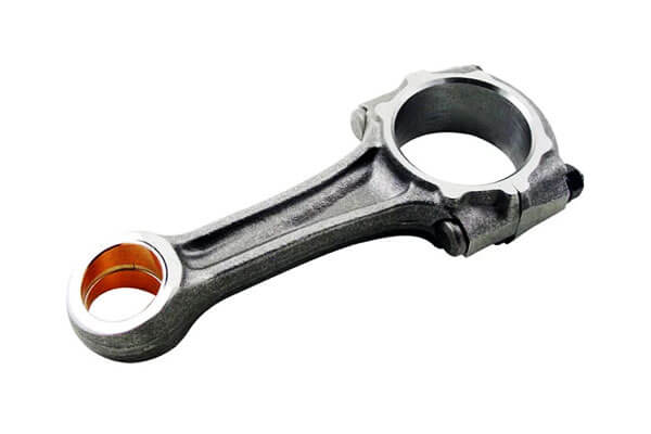
6. Апрацоўка шатуноў: Кантроль дэфармацыі для кампанентаў нізкай жорсткасці
Шатуны звязваюць поршань з каленчатым валам і перадаюць пераменныя сілы, якія ўзнікаюць падчас зваротна-паступальнага руху.
Яны павінны вытрымліваць вялікія цыклічныя нагрузкі, ўздзеянне, выгін, і стомленасць, застаючыся досыць лёгкім, каб мінімізаваць зваротна-паступальную масу.
Большасць звычайных шатуноў вырабляюцца з каваная сталь, хоць алюміній і іншыя спецыялізаваныя сплавы выкарыстоўваюцца ў пэўных прыкладаннях.
З пункту гледжання апрацоўкі, шатуны з'яўляюцца складанай задачай, таму што іх выцягнутая структура і розны папярочны перасек забяспечваюць ім адносна нізкую мясцовую калянасць.
У выніку, сіла заціску, сіла рэзання, а рэшткавае напружанне можа выклікаць дэфармацыю, што ўскладняе захаванне дакладнай геаметрыі адтуліны і міжцэнтральнай адлегласці.
Тыповы працэс апрацоўкі шатуна
Агульны маршрут працэсу можа быць:
Коўка → тэрмічная апрацоўка → базавая апрацоўка → чарнавая знешняя апрацоўка → апрацоўка адтуліны → аддзяленне вечкаў → паўаздабленне → дакладнае расточванне/хонінгаванне → канчатковая праверка
Паслядоўнасць вар'іруецца ў залежнасці ад канструкцыі шатуна і ад таго, ці выкарыстоўваецца звычайная апрацоўка або тэхналогія разлому.
Чарнавая апрацоўка стварае стабільныя эталонныя паверхні і выдаляе большую частку прыпуску на апрацоўку.
Затым для дасягнення канчатковых памераў адтуліны і геаметрычнай дакладнасці выкарыстоўваюцца дакладныя расточвання і хонінгаванне.
Апрацоўка адтулін і аздабленне
Свідравіны вялікага і малога канцоў звычайна апрацоўваюцца праз паслядоўнасць грубага расточвання, паўфініш, і дакладнасць аздаблення.
сумна усталёўвае дакладны памер і геаметрычную форму, прамежак часу даводзячы можа яшчэ больш палепшыць круглявасць, цыліндрычнасць, і характарыстыкі паверхні, дзе патрабуецца.
Для буйнагабарытнай зборкі, адносіны паміж стрыжнем і вечкам асабліва важныя.
Пасля каўпачок аддзяляецца і зноў збіраецца, гатовы канал павінен захоўваць запраектаваную геаметрыю і выраўноўванне.
Пералом-разрыў шатунаў
Разлом шырока выкарыстоўваецца для падыходных шатунных канструкцый вялікага аб'ёму.
Замест таго, каб вырабляць звычайна апрацаваную сумежную паверхню паміж стрыжнем і вечкам, кантраляваны пералом ініцыюецца ўздоўж загадзя вызначанай вобласці.
Атрыманыя ў выніку нерэгулярныя грані пераломаў забяспечваюць вельмі індывідуальны інтэрфейс спарвання, дапамагаючы вечку і стрыжню вярнуцца ў зыходнае адноснае становішча падчас зборкі.
Такі падыход можа прапанаваць:
- Дакладнае размяшчэнне крышкі да стрыжня
- Зніжэнне адноснага руху
- Выключэнне некаторых звычайных аперацый механічнай апрацоўкі
- Эфектыўная масавая вытворчасць
- Паслядоўнае размяшчэнне зборкі пры належным кантролі
Аднак, расшчапленне разлому патрабуе старанна кантраляваных уласцівасцяў матэрыялу, геаметрыя выемкі, паводзіны пералому, і параметры працэсу. Ён не падыходзіць для любога матэрыялу або канструкцыі шатуна.
Асноўны прынцып апрацоўкі шатуна
Фундаментальная задача заключаецца ў захаванні дакладных прасторавых адносін паміж адтулінамі вялікага і малога канцоў, адначасова прадухіляючы дэфармацыю адносна тонкага кампанента.
Гэта робіць апрацоўку шатуна класічным прыкладам дакладнай вытворчасці з нізкай жорсткасцю. Адна толькі дакладнасць машыны не можа гарантаваць канчатковы вынік.
Працэс павінен адначасова кантраляваць выбар базы дадзеных, загрузка прыстасаванняў, сіла рэзання, выдаленне матэрыялу, тэрмічная апрацоўка, аздабленне адтуліны, і інспекцыя.
У масавай аўтамабільнай вытворчасці, найбольш эфектыўны працэс, такім чынам, спалучае жорсткае і паўтаральнае мацаванне з кантраляванымі параметрамі апрацоўкі, аўтаматызаванае вымярэнне, і, дзе гэта дарэчы, тэхналогія пералом-раскол.
7. Параўнанне шасці тыповых дэталяў апрацоўкі
Хоць валы, рукавы, дапрацоўкі, перадачы, поршні, і шатуны маюць вельмі розныя геаметрыі, іх логіку планавання працэсу можна сістэматычна параўноўваць.
| Тып дэталі | Выклік першаснай апрацоўкі | Крытычныя асаблівасці | Агульныя працэсы | Асноўны кантрольны пункт |
| Вал | Дакладнасць кручэння і канцэнтрычнасць | Часопісы, плечы, ніткі, шпонкавыя пазы | Паварот, драба, шлицевая апрацоўка | Сувосевасць і біенне |
| Рукаў | Дакладнасць адтуліны і дэфармацыя | Свідраваць, OF, тарэц | Свідраванне, нудны, рассверливание, даводзячы | Адносіны адтуліны да вонкавага боку |
| Жыллё | Дакладнасць дату і сістэмы адтулін | Мантажныя грані, свідравіны, адтуліны | Фрэзы, нудны, свідраванне, драба | Палажэнне і геаметрычная дакладнасць |
| рыштунак | Геаметрыя зуба і дэфармацыя тэрмічнай апрацоўкі | Профіль зуба, кіраваць, стой, назаляць | Хобінг, фарміраванне, галенне, даводзячы, драба | Дакладнасць перадач і біццё |
| Поршань | Функцыянальны профіль і цеплавая геаметрыя | спадніца, адтуліну шпількі, колцавыя пазы | Паварот, нудны, апрацоўка паз | Профіль і пазіцыйная дакладнасць |
| Шатун | Нізкая калянасць і дэфармацыя | Свідравіны малога/вялікага канца | Фрэзы, нудны, даводзячы, расшчапленне пералому | Выраўноўванне адтулін і міжцэнтральная адлегласць |
Табліца паказвае важную заканамернасць: метад апрацоўкі павінен адпавядаць функцыянальнай геаметрыі дэталі.
Універсальна лепшага працэсу апрацоўкі не існуе.
Тачэнне ідэальна падыходзіць для паверхняў, якія верцяцца, свідраванне неабходна для дакладнага ўнутранага дыяметра, на складаных прызматычных паверхнях пераважае фрэзераванне, шліфоўка забяспечвае высокую дакладнасць пасля тэрмічнай апрацоўкі, і працэсы фармавання або разлому могуць знізіць патрабаванні да механічнай апрацоўкі адпаведных кампанентаў вялікага аб'ёму.
8. Conclusion
Шэсць рэпрэзентатыўных тыпаў частак -шахты, рукавы, дапрацоўкі, перадачы, поршні, і шатуны— забяспечыць карысны перасек практыкі механічнай апрацоўкі.
Нягледзячы на адрозненні, адны і тыя ж фундаментальныя прынцыпы з'яўляюцца зноў і зноў:
Правільны выбар базы → лагічная паслядоўнасць працэсу → адпаведныя метады апрацоўкі → эфектыўны кантроль дэфармацыі → надзейны кантроль
Гэта сапраўдная аснова праектавання працэсу апрацоўкі.
Мэта складаецца не толькі ў тым, каб выдаліць матэрыял як мага хутчэй.
Паспяховы працэс апрацоўкі павінен ператварыць нарыхтоўку ў кампанент, які адпавядае яе памерах, геаметрычны, функцыянальны, металургічны, паверхні, і эканамічныя патрабаванні паслядоўна.
Для інжынераў, планіроўшчыкі працэсаў, і вытворцы, разуменне гэтых шасці тыповых катэгорый дэталяў дае больш, чым спіс метадаў апрацоўкі.
Ён прапануе практычную аснову для аналізу незнаёмых кампанентаў і выбару маршруту працэсу на аснове структуры дэталі, функцыянальныя патрабаванні, матэрыяльныя паводзіны, дакладнасць, і аб'ём вытворчасці.
FAQ
Якая частка з гэтых шасці тыпаў з'яўляецца самай складанай для апрацоўкі?
Гэта залежыць ад ступені дакладнасці, але ў цэлым шасцярні і поршні ўяўляюць найбольшую складанасць працэсу.
Шасцярні патрабуюць спецыяльнай апрацоўкі профілю зубоў і жорсткіх геаметрычных допускаў, у той час як поршні патрабуюць дакладнага кантролю складаных выгнутых профіляў і некалькіх перадач базавых дадзеных.
Гэты працэс забяспечвае найвышэйшую якасць зуб'я перадач?
Шліфаванне шасцярні забяспечвае найвышэйшую дакладнасць профілю зубоў і з'яўляецца стандартным працэсам для прэцызійных загартаваных шасцярняў.
Ён можа выправіць скажэнні ад тэрмічнай апрацоўкі і дасягнуць найвышэйшай ступені дакладнасці AGMA або DIN.
Чаму выбар базы так важны пры апрацоўцы корпуса?
Корпусы маюць некалькі ўзаемазвязаных сістэм адтулін і спалучаных граняў. Усе пазіцыйныя допускі складаюцца з асноўнай базы.
Дрэнны выбар базы стварае сукупную памылку выраўноўвання, якая непасрэдна пагаршае пасадку зборкі і прадукцыйнасць машыны.
Якая карысць ад разлому для шатуноў?
Пералом расшчапленне стварае ідэальна падабраныя, форма фіксацыі інтэрфейсу паміж стрыжнем і вечкам.
Гэта павышае дакладнасць зборкі, выключае механічную апрацоўку спалучанай паверхні, памяншае колькасць частак, і павялічвае структурную цэласнасць вялікага канца.
Якая стандартная аздабленне для адтулін утулкі падшыпніка?
Большасць прэцызійных адтулін падшыпнікаў аздабляюцца шляхам хонінгавання, што дае выдатную круглявасць, кантраляваная тэкстура паверхні, і паслядоўны памер.
Для вельмі дакладных прыкладанняў, можа быць указана шліфоўка адтуліны або суперфінішная апрацоўка.