
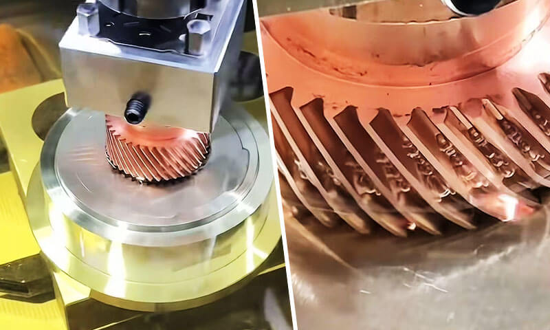
Sinker elektriese ontlading bewerking, ook na verwys as ram EDM, die-sinkende EDM of holte EDM, is een van die mees presiese en onvervangbare nie-tradisionele vervaardigingsprosesse in moderne presisie-ingenieurswese.
Anders as konvensionele maal en draai wat materiaal verwyder deur meganiese snykrag, sinker EDM erodeer elektries geleidende werkstukke deur beheerde, herhalende elektriese vonke, met geen fisiese kontak tussen die gereedskap en die onderdeel nie.
Hierdie fundamentele verskil laat dit toe om komplekse driedimensionele holtes te produseer, skerp interne hoeke, diep smal gleuwe en ultra-harde materiaalkenmerke wat onmoontlik of buitensporig duur sou wees om met snygereedskap te vervaardig.
Vir dekades lank, sinker EDM was die ruggraat van gereedskap- en matrysvervaardiging, en dit gaan voort om innovasie in lugvaart moontlik te maak, mediese toestelle, motor- en halfgeleierindustrieë.
Sy unieke vermoë om geharde staal te bewerk, gesementeerde karbiede, en spesiale superlegerings tot mikronvlak-akkuraatheid, met geen snykragte en braamvrye rande, maak dit onontbeerlik vir hoë-waarde presisie komponente.
1. Wat is sinker EDM?
Sinker EDM(Elektriese ontladingsbewerking) is 'n nie-kontak termo-elektriese materiaal verwydering proses waarin 'n vooraf gevormde elektrode (gereedskap) en 'n geleidende werkstuk word ondergedompel in diëlektriese vloeistof en geskei deur 'n klein, presies beheerde vonkgaping.
'n Reeks diskrete elektriese ontladings word oor die gaping gegenereer, elkeen produseer 'n gelokaliseerde mikroplasmakanaal met temperature van 8 000–12 000°C wat klein volumes van beide werkstuk en elektrodemateriaal smelt en verdamp.
Meer as miljoene ontladingsiklusse, die elektrode sink geleidelik in die werkstuk in, om sy omgekeerde vorm met hoë akkuraatheid weer te gee.

Die naam "sinker" kom van hierdie duikaksie: die elektrode sink letterlik in die deel om 'n holte te vorm.
Anders as ander EDM-variante, sinker EDM word gedefinieer deur sy vermoë om ten volle driedimensionele interne en eksterne vorms te produseer, eerder as om net deur profiele te sny.
Dit is die oorspronklike vorm van EDM-tegnologie en bly die mees veelsydige variant vir komplekse holtewerk.
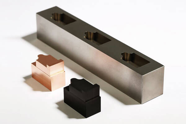
'n Sleutel onderskeidende kenmerk is dat die geometrie van die voltooide deel 'n direkte negatiewe replika van die elektrode is.
Dit beteken elke detail van die elektrode - ribbes, gleuwe, teksture en hoekradiusse — word na die werkstuk oorgedra, geskaal volgens die grootte van die vonkgaping.
Historiese Konteks
Die EDM-proses is die eerste keer in die 1940's ontwikkel deur twee Sowjet-wetenskaplikes, B.R. Lazarenko en N.I. Lazarenko, wat ontdek het dat elektriese ontladings gebruik kan word om metaal te erodeer.
Die tegnologie is gedurende die 1950's en 1960's verder verfyn, en teen die 1970's, Sinker EDM het 'n gevestigde vervaardigingsproses geword vir die maak van gereedskap en matrijs.
Vandag, dit is 'n hoeksteen van presisievervaardiging, veral in die lugvaart, motorvoertuig, medies, en vormvervaardigingsbedrywe.
2. Hoe werk sinker EDM?
Sinker EDM, Ook bekend as die-sinkende EDM of elektriese ontlading bewerking, verwyder materiaal deur 'n beheerde volgorde van elektriese ontladings eerder as deur direkte meganiese sny.
Die proses gebruik 'n gevormde elektrode, 'n geleidende werkstuk, en 'n diëlektriese vloeistof.
Deur herhaaldelik mikroskopiese vonke oor 'n presies beheerde gaping te genereer, Sinker EDM reproduseer geleidelik die elektrodegeometrie in die werkstuk.
Anders as konvensionele bewerking, daar is geen direkte kontak tussen die elektrode en werkstuk tydens normale ontladingsbewerking nie.
Materiaalverwydering word hoofsaaklik deur elektriese pulsenergie beheer, ontladingsfrekwensie, gapingstoestande, diëlektriese sirkulasie, en elektrode beweging.
Diëlektriese ineenstorting
Die proses begin met die elektrode wat uiters naby aan die geleidende werkstuk geposisioneer is terwyl albei in diëlektriese vloeistof gedompel is, tipies EDM olie.
'n Beheerde spanning word tussen die elektrode en werkstuk aangelê. Onder normale omstandighede, die diëlektrikum dien as 'n elektriese isolator.
Soos die elektrode die werkstuk nader en die inter-elektrode gaping bereik 'n geskikte vlak, die elektriese veld word voldoende sterk om die diëlektrikum plaaslik te ioniseer.
Die vloeistof ondergaan dan diëlektriese ineenstorting, skep 'n tydelike geleidende plasmakanaal tussen die twee oppervlaktes.
Omdat die ontlading by gelokaliseerde punte plaasvind waar elektriese toestande die gunstigste is, die bewerkingsproses kan energie in uiters klein areas konsentreer.
Elektriese ontlading en gelokaliseerde energievrystelling
Sodra ineenstorting plaasvind, 'n kortstondige stroompuls gaan deur die plasmakanaal. Die elektriese energie word omgeskakel in intense gelokaliseerde termiese energie.
Temperature binne die ontladingsone kan etlike duisende grade Celsius bereik.
Hierdie uiterste maar hoogs gelokaliseerde energie produseer vinnige verhitting van beide die werkstuk en, tot 'n mindere mate, die elektrode.
Die afvoer verwyder nie materiaal deur 'n deurlopende snyaksie nie. In stede van, elke individuele vonk skep 'n mikroskopiese bewerkingsgebeurtenis. Die gekombineerde effek van miljoene van hierdie gebeurtenisse produseer geleidelik die gewenste holte.
Smelt en verdamping van die werkstuk
Die gekonsentreerde termiese energie smelt vinnig en verdamp 'n baie klein volume materiaal op die werkstukoppervlak gedeeltelik. 'n Mikroskopiese krater word na elke effektiewe ontlading gevorm.
Die afmetings van hierdie kraters hang sterk af van bewerkingsparameters soos:
- Piek ontladingsstroom
- Duur van pols aan
- Duur van polsslag
- Ontladingsspanning
- Elektrode-werkstuk gaping
- Diëlektriese toestande
Hoër ontladingsenergie verhoog gewoonlik die materiaal verwydering tempo (MRR), maar dit kan ook groter kraters produseer, 'n growwer oppervlak, 'n dikker hervormde laag, en 'n groter hitte-geaffekteerde streek.
Laer-energie afwerkingspulse genereer baie kleiner kraters en word dus gebruik wanneer dimensionele akkuraatheid en oppervlakkwaliteit belangriker is as verwyderingstempo.
Deionisasie en diëlektriese spoeling
Na elke ontslag pols, die stroom word onderbreek. Die plasmakanaal stort ineen en die diëlektrikum keer vinnig terug na sy isolerende toestand.
Terselfdertyd, diëlektriese sirkulasie verwyder gesmelte deeltjies, herstolde puin, en ander kontaminante van die bewerkingsgaping.
Effektiewe spoeling is noodsaaklik omdat opgehoopte puin onstabiele sekondêre ontladings kan skep, kortsluitings, boogvorming, of ongelyke materiaalverwydering.
Die diëlektrikum verrig dus verskeie funksies gelyktydig: elektriese isolasie, verkoeling, rommel verwydering, en herstel van stabiele gapingstoestande.
Servo gaping beheer
'N kritieke kenmerk van Sinker EDM is die geslote-lus servo stelsel wat deurlopend elektriese toestande in die bewerkingsgaping monitor en elektrodeposisie dienooreenkomstig aanpas.
As die gaping buitensporig klein word, onstabiele ontladings of kortsluitings kan voorkom, dus trek die elektrode effens terug.
As die gaping te groot word, ontladings word selde of stop, wat die elektrode aangespoor het om te beweeg.
Hierdie deurlopende terugvoer handhaaf 'n toepaslike werkgaping regdeur bewerking.
Omdat die elektrode progressief die finale holte-geometrie nader terwyl beheerde ontladingstoestande gehandhaaf word, komplekse holtes kan met hoë herhaalbaarheid gegenereer word.
Progressiewe holtevorming
Die elektrode produseer gewoonlik nie die volledige holte in 'n enkele ontlading nie. In stede van, duisende of miljoene individuele ontladings erodeer die werkstuk geleidelik.
Soos die proses voortduur, die elektrode beweeg in die werkstuk in terwyl sy geprogrammeerde trajek behou word. Die gevolglike holte voldoen toenemend aan die negatiewe geometrie van die elektrode.
Vir presisie vorm- en matrijstoepassings, masjinering word algemeen in grofwerk verdeel, semi-afwerking, en afronding stadiums.
Grofwerk gebruik relatief hoë-energie pulse om materiaal doeltreffend te verwyder, terwyl afwerking laer-energie-ontladings gebruik om strenger dimensionele beheer en verbeterde oppervlakkwaliteit te verkry.
3. Die Sinker EDM-bewerkingsproses stap vir stap
Sinker EDM is nie bloot 'n vonkgenerasie-operasie nie.
Om 'n presiese EDM-holte te produseer, vereis gekoördineerde beheer van elektrodegeometrie, werkstuk posisionering, diëlektriese sirkulasie, ontladingsparameters, elektrode slytasie, spoel, en inspeksie.
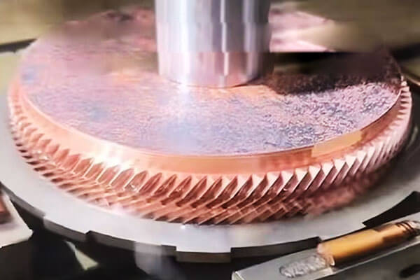
Stap 1: Elektrode-ontwerp en -vervaardiging
Die proses begin met die ontwerp van 'n elektrode wat die positiewe geometrie van die holte wat gemasjineer moet word.
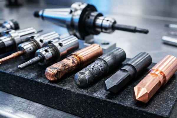
Grafiet en koper is die twee elektrodemateriale wat die meeste gebruik word, gekies volgens faktore soos holte kompleksiteit, vereiste oppervlakafwerking, Dimensionele akkuraatheid, bewerking spoed, en verwagte elektrodeslytasie.
Elektrode-ontwerp moet rekening hou met die geprogrammeerde vonk gaping, elektrode slytasie, spoelvereistes, en die dimensionele kompensasie wat deur die EDM-beheerstelsel vereis word.
Vir komplekse vorms en matryse, veelvuldige elektrodes kan vir grofwerk vervaardig word, semi-afwerking, en afronding eerder as om die finale holte met 'n enkele elektrode te probeer bereik.
Die kwaliteit van die elektrode beïnvloed direk die kwaliteit van die finale holte.
Foute in elektrode afmetings, Skerp rande, oppervlak toestand, of belyning kan tydens EDM na die werkstuk oorgedra word.
Stap 2: Werkstukopstelling en presisiebelyning
Die werkstuk is veilig op die EDM-masjientafel gemonteer en binne die diëlektriese tenk geplaas.
Akkurate belyning vestig die koördinaatverhouding tussen die werkstuk en elektrode, wat noodsaaklik is wanneer holtes gemasjineer word wat presies met ander kenmerke moet ooreenstem.
Moderne Sinker EDM-masjiene word algemeen gebruik aanraaksondes, outomatiese randopsporing, verwysingstelsels, of elektrodemetingsiklusse om werkstuknulpunte te vestig en elektrodeposisie te verifieer.
Vir multi-elektrode bewerking, konsekwente koördinaatverwysing is veral belangrik omdat rofwerk, afwerking, en detail-elektrodes moet na die korrekte liggings terugkeer sonder om kumulatiewe posisioneringsfoute in te voer.
Stap 3: Diëlektriese voorbereiding en spoel
Die bewerkingsone word gevul of ondergedompel met diëlektriese vloeistof. EDM olie word wyd gebruik vir konvensionele Sinker EDM omdat dit stabiele elektriese isolasie en effektiewe verkoeling bied.
Die diëlektrikum word voortdurend deur filtrasie- en spoelstelsels gesirkuleer om bewerkingsrommel te verwyder.
Diëlektriese netheid en temperatuurstabiliteit is belangrik omdat besmette of termies onstabiele vloeistof ontladingsgedrag en dimensionele konsekwentheid kan beïnvloed.
Spoel is ewe krities. Tydens bewerking, gesmelte en hergestolde deeltjies versamel in die holte.
As hierdie deeltjies nie effektief verwyder word nie, hulle kan onstabiele ontladings veroorsaak, sekondêre boogvorming, verminderde materiaalverwyderingsdoeltreffendheid, en gelokaliseerde oppervlakdefekte.
Stap 4: EDM Parameter Programmering
Voordat bewerking begin, die proses ingenieur stel die elektriese en servo parameters volgens die werkstuk materiaal, elektrode materiaal, bewerking stadium, holte meetkunde, en vereiste oppervlakafwerking.
Belangrike parameters sluit piekstroom in, ontladingsspanning, pols-aan tyd, pols-af tyd, servo verwysing, polariteit, spoeltoestande, en elektrode wentel- of bewegingstrategieë waar van toepassing.
Daar is geen enkele universele EDM-parameterstel nie. Grofwerk verg aansienlik meer ontladingsenergie as afwerking, terwyl diep smal holtes verskillende spoel- en polstoestande van oop holtes kan vereis.
Stap 5: Rofwerk
Ruwe EDM verwyder die meerderheid van die materiaal en vestig die basiese holte-geometrie. Relatief hoë ontladingsenergie word gebruik om 'n hoë materiaalverwyderingstempo te bereik.
Gedurende hierdie stadium, groter elektriese pulse produseer groter individuele kraters en dus vinniger erosie.
'n Beheerde hoeveelheid bewerkingstoelaag word doelbewus gelaat vir daaropvolgende bewerkings.
Die doel van rofwerk is nie maksimum oppervlakkwaliteit nie, maar doeltreffende en stabiele verwydering van grootmaatmateriaal terwyl voldoende dimensionele beheer vir afwerking gehandhaaf word.
Vir diep holtes, spoeltoestande word veral belangrik tydens grofwerk omdat die groter hoeveelheid geërodeerde materiaal die bewerkingsgaping vinnig kan besoedel.
Stap 6: Semi-afwerking en elektrode-oorgang
Vir veeleisende holtes, 'n semi-afwerking stadium kan ingestel word tussen grof en finale afwerking.
'n Afsonderlike elektrode of 'n progressief verfynde elektrodegeometrie kan gebruik word om die oorblywende bewerkingstoelae te verwyder terwyl dimensionele afwyking verminder word en oppervlakkonsekwentheid verbeter word.
Hierdie tussenstadium verskaf 'n beheerde oorgang tussen aggressiewe ruwerk en delikate afwerking.
Dit is veral nuttig vir vorms en matryse wat bevat diep ribbes, smal gleuwe, skerp hoeke, fyn teksture, of komplekse driedimensionele oppervlaktes.
Stap 7: Afwerking
Afwerking gebruik aansienlik laer ontladingsenergie om die finale holteafmetings en vereiste oppervlakkwaliteit te produseer.
Korter pulsduur en laer piekstrome skep kleiner erosiekraters, oppervlakruwheid te verminder en die dikte van die termies geaffekteerde oppervlaklaag te verminder.
Die afrondingstrategie moet balanseer oppervlak ruwheid, Dimensionele akkuraatheid, bewerkingstyd, en oppervlak integriteit.
Uiters fyn afwerking kan veelvuldige passe vereis omdat materiaalverwydering geleidelik stadiger word namate ontladingsenergie afneem.
Vir kritieke gereedskaptoepassings, die finale oppervlak kan later gepoleer word, teksturering, laag, of ander oppervlakbehandelings afhangende van die vereiste funksie.
Stap 8: Elektrodeslytasievergoeding
Elektrodeslytasie is 'n inherente kenmerk van Sinker EDM. Alhoewel die werkstuk gewoonlik vinniger as die elektrode geërodeer word, die elektrode verander geleidelik van vorm tydens bewerking.
Dra is veral belangrik rondom Skerp rande, hoeke, Klein kenmerke, en gebiede wat aan gekonsentreerde ontladingsaktiwiteit blootgestel is.
Moderne EDM-kontroles vergoed vir elektrodeslytasie deur elektrodebeweging en bewerkingsparameters aan te pas.
Vir hoë-presisie holtes, elektrodeslytasie moet ook in ag geneem word tydens elektrodeontwerp en dimensionele inspeksie.
Stap 9: Finale inspeksie
Na EDM-bewerking, die holte word skoongemaak en teen die ingenieursvereistes geïnspekteer.
Dimensionele inspeksie kan uitgevoer word met behulp van a CMM, EDM-spesifieke ondersoekstelsel, optiese meettoerusting, of presisiemeters, afhangende van die komponent geometrie en toleransie vereistes.
Oppervlakgrofheid kan met behulp van 'n profilometer geëvalueer word, terwyl kritieke holte-afmetings en meetkundige verwantskappe teen die CAD-model of tekening geverifieer word.
Indien inspeksie gelokaliseerde afwykings identifiseer, addisionele EDM-afwerkingspasse kan dikwels uitgevoer word sonder om die hele vervaardigingsproses te vervang.
4. Elektrodes vir Sinker EDM
Die elektrode is een van die belangrikste elemente in sinker EDM omdat sy geometrie direk na die werkstuk oorgedra word deur beheerde elektriese erosie.
Anders as 'n konvensionele snygereedskap, 'n EDM-elektrode moet gelyktydig elektriese geleidingsvermoë verskaf, Dimensionele stabiliteit, dra weerstand, en akkurate meetkundige reproduksie.
Elektrode materiaal
| Materiaal | Sleuteleienskappe | Voordele | Beperkings | Tipiese toepassings |
| Grafiet | Hoë elektriese geleidingsvermoë; lae slytasie; Goeie bewerkbaarheid; hoë smeltpunt. | Uitstekend vir grofwerk; lae elektrodeslytasie; goeie oppervlakafwerking; koste-effektief. | Bros; kan fyn stof produseer; vereis gespesialiseerde snygereedskap. | Skimmelholtes; skei; grofwerk en afronding. |
| Koper | Uitstekende elektriese geleidingsvermoë; goeie termiese geleidingsvermoë; maklik om te bewerk. | Goed vir afronding; fyn oppervlakafwerking; maklik om te elektroplateer. | Hoër slytasie as grafiet; laer materiaalverwyderingstempo. | Afwerking; klein holtes; delikate kenmerke. |
| Koperwolfram | Hoë smeltpunt; Uitstekende slytasie weerstand; goeie termiese geleidingsvermoë. | Uitstekende slytasie weerstand; goed vir fyn afwerking; stabiele afmetings. | Duur; moeilik om te masjineer. | Presisie afwerking; klein elektrodes; hoë-slytasie toepassings. |
Silwer-Wolfram |
Uitstekende geleidingsvermoë; hoë smeltpunt; goeie slytasieweerstand. | Baie lae slytasie; uitstekende afwerking. | Baie duur. | Hoë-presisie afwerking; hoëwaarde-toepassings. |
| Wolfraam | Baie hoë smeltpunt; Uitstekende slytasie weerstand. | Baie lae slytasie; goeie afwerking. | Uiters duur; moeilik om te masjineer. | Gespesialiseerde hoë-presisie toepassings. |
5. Akkuraatheid, Oppervlakafwerking en bewerkingsvermoë
Een van die belangrikste sterkpunte van Sinker EDM is sy vermoë om hoë dimensionele beheer te kombineer met die bewerking van geometrieë wat moeilik of onmoontlik is om doeltreffend te vervaardig met behulp van konvensionele snygereedskap.
Dimensionele akkuraatheid
Met moderne CNC Sinker EDM toerusting en 'n goed beheerde proses, dimensionele toleransies in die paar-mikron tot 'n paar-tiene-mikron reeks is haalbaar vir geskikte geometrieë.
Die finale resultaat hang baie af van elektrodeslytasievergoeding, termiese beheer, diëlektriese stabiliteit, en inspeksiemetodologie.
| Parameter | Tipiese vermoë | Ingenieursoorwegings |
| Dimensionele toleransie | ±0,005–0,02 mm | Strenger toleransies kan onder geoptimaliseerde afwerkingstoestande bereik word |
| Hoë-presisie verdraagsaamheid | Ongeveer ±0,002–0,005 mm | Vereis gewoonlik beheerde termiese toestande, presisie elektrodes, en toegewyde afrondingspasse |
| Posisionering akkuraatheid | Ongeveer ±0,003–0,01 mm | Hang af van masjienkonfigurasie, as kalibrasie, en werkstukopstelling |
| Herhaalbaarheid | Ongeveer ±0,002–0,005 mm | Sterk beïnvloed deur masjientoestand en prosesstabiliteit |
| Elektrode-tot-holte akkuraatheid | Tipies binne verskeie mikrometers tot tientalle mikrometers | Hang af van elektrode-inspeksie, dra vergoeding, en vonk-gaping beheer |
Oppervlakafwerking
Sinker EDM produseer 'n kenmerkende oppervlak wat bestaan uit mikroskopiese ontladingskraters.
Oppervlakgrofheid word hoofsaaklik deur ontladingsenergie beheer: hoër-energie pulse produseer dieper en groter kraters, terwyl laer-energie afwerkingspulse 'n fyner oppervlaktekstuur genereer.
Tipiese bereikbare oppervlakruwheidsreekse word hieronder getoon.
| Oppervlakgrofheid Ra | Ongeveer. Grofheid (µin) | Tipiese bewerkingstoestand | Tipiese gebruik |
| 0.2–0,4 µm | 8–16 µmin | Baie lae-energie afwerking | Presisie vorms, gereedskapoppervlaktes van optiese gehalte wat verdere polering benodig |
| 0.4–0,8 µm | 16–32 µmin | Fyn afwerking | Skimmelholtes, presisie sterf, funksionele oppervlaktes |
| 0.8–1,6 µm | 32–63 µmin | Algemene afwerking | Algemene presisiegereedskap en ingenieurskomponente |
| 1.6–3,2 µm | 63–125 µmin | Medium-energie bewerking | Voorlopige holtes en oppervlaktes waar matige grofheid aanvaarbaar is |
| >3.2 µm | >125 µin | Hoë-energie grofwerk | Grootmaat materiaal verwydering voor afwerking |
Die finale oppervlakkwaliteit word nie deur stroom alleen bepaal nie. Polsduur, pols interval, polariteit, diëlektriese spoeling, elektrode materiaal, werkstuk materiaal, en die aantal afrondingspasse
Bewerkingsvermoë
Sinker EDM is veral waardevol wanneer die komponent bevat diep holtes, smal ribbes, ingewikkelde sakke, klein interne radiusse, skerp meetkundige oorgange, of komplekse driedimensionele kontoere.
| Kenmerk | Tipiese vermoë | Ingenieursoorwegings |
| Minimum kenmerkgrootte | Ongeveer 0,05–0,10 mm | Hoogs afhanklik van elektrodesterkte, spoel, aspekverhouding, en energie ontslaan |
| Klein interne radius | Ongeveer 0,05–0,15 mm | Beperk deur elektrodegeometrie en elektrodeslytasie |
| Diep smal kenmerke | Aspekverhoudings van ongeveer 10:1–20:1 moontlik is | Spoel word al hoe moeiliker namate die diepte toeneem |
| Holte diepte | Tot ongeveer 100–200 mm of meer | Hoofsaaklik beperk deur elektrode-ontwerp, spoel, masjienslag, en holte meetkunde |
Komplekse 3D-holtes |
Uitmuntend | Komplekse elektrodegeometrieë kan hoogs ingewikkelde holtevorms weergee |
| Geharde staal bewerking | Uitmuntend | Veral voordelig na hittebehandeling |
| Skerp interne kenmerke | Uitmuntend | Meer prakties as konvensionele roterende gereedskap vir baie interne geometrieë |
| Blinde holtes | Uitmuntend | 'n Belangrike toepassing van sinkende EDM |
| Dun ribbes en smal gleuwe | Uitmuntend | Vereis noukeurige elektrodeontwerp en beheerde ontladingsenergie |
6. Watter materiale kan deur Sinker EDM gemasjineer word?
N groot voordeel van sinker EDM (Elektriese ontladingsbewerking) is sy vermoë om elektries geleidende materiale te bewerk, ongeag hul hardheid of meganiese sterkte.
| Materiële Familie | Tipiese materiale | Geskiktheid | Tipiese Sinker EDM-toepassings |
| Gereedskapstaal | H13, D2, S7, P20, 4140, 4340 | Uitmuntend | Inspuitvorms, Stamp Sterf, slaan, holtes vorm, geharde gereedskap |
| Vlekvrye staal | 304, 316, 17-4Ph, 440C | Uitmuntend | Mediese komponente, Presisie gereedskap, lugvaartonderdele, voedselverwerkingstoerusting |
| Superalloys | Inklok 625, Inklok 718, Hastelloy, Waspaloy | Uitmuntend | Lugvaartkomponente, turbineverwante gereedskap, chemiese verwerkingstoerusting |
| Titaan legerings | Ti-6Al-4V en ander geleidende titaniumlegerings | Uitmuntend | Lugvaartonderdele, mediese komponente, presisie holtes en gereedskap |
Gesementeerde karbiede |
WC-Co en ander geleidende karbied grade | Uitmuntend | Snygereedskap, slytvaste komponente, slaan, skei, Presisie gereedskap |
| Koperlegerings | Koper, brons, brons, berillium koper | Uitmuntend | Elektriese komponente, presisie holtes, kontakte, hitte-oordrag komponente |
| Aluminiumlegerings | 6061, 7075 en ander geleidende grade | Goed | Prototipes, vorms, lae-volume presisie komponente, komplekse holtes |
| Ander geleidende materiale | Sekere geleidende spesialiteitslegerings en komposiete | Toepassing-afhanklik | Gespesialiseerde gereedskap en moeilik bewerkbare komponente |
7. Sinker EDM vs. Draad EDM vs. CNC -bewerking
Sinker EDM, draad EDM, en CNC-bewerking is almal presisievervaardigingstegnologieë, maar hulle verwyder materiaal op fundamenteel verskillende maniere.
| Kriterium | Sinker EDM | Draad EDM | CNC -bewerking |
| Materiaal verwydering | Elektriese ontlading erosie | Elektriese ontlading erosie | Meganiese sny |
| Gereedskap | Gevormde elektrode | Deurlopende draadelektrode | Snygereedskap |
| Materiële vereiste | Elektries geleidend | Elektries geleidend | Oor die algemeen bewerkbare materiale |
| Beste vir | Holtes, blinde gate, komplekse 3D kenmerke | Profiele, gleuwe, kontoere, deur-snitte | Algemene prismatiese en roterende dele |
| Harde materiale | Uitmuntend | Uitmuntend | Gereedskap-afhanklik |
| Blinde holtes | Uitmuntend | Nie normaalweg geskik nie | Goed, geometrie-afhanklik |
| Komplekse interne meetkunde | Uitmuntend | Beperk deur draadtoegang | Matig tot uitstekend |
Skerp interne hoeke |
Baie goed, elektrode-afhanklik | Uitmuntend | Beperk deur gereedskap deursnee |
| 3D holte bewerking | Uitmuntend | Beperk | Goed met multi-as bewerking |
| Materiaal verwydering koers | Gematig | Gematig | Oor die algemeen hoog |
| Oppervlakafwerking | Uitstekend met afrondingspasse | Uitstekend met afrondingspasse | Uitmuntend, afhangende van gereedskap |
| Fisiese snykrag | In wese geen | In wese geen | Betekenisvol |
| Elektrode/gereedskapslytasie | Elektrodeslytasie vind plaas | Draad word voortdurend verbruik | Slytasie van snygereedskap |
| Tipiese toepassings | Vorms, skei, slaan, holtes | Presisie profiele, gleuwe, slaan | Asse, huise, plate, Strukturele komponente |
8. Voordele en beperkings van Sinker EDM
Belangrike voordele
- Hardheid-onafhanklike bewerking: Sny geharde staal, karbied en superlegerings so maklik soos sagte staal; bewerking kan na hittebehandeling uitgevoer word om vervorming te vermy.
- Komplekse 3D holte vermoë: Produseer interne geometrieë, skerp hoeke en diep ribbes wat nie met roterende snyers bereik kan word nie.
- Geen snykragte nie: Geen meganiese kontak beteken geen defleksie nie, geen gesels nie, geen brame en geen oorblywende snyspanning nie, selfs vir ultra-dun mure en delikate kenmerke.
- Uiters hoë presisie: Bereik mikronvlak toleransies met uitstekende herhaalbaarheid vir hoëvolume produksie.
- Superieure oppervlakafwerking: In staat om oppervlaktes van spieëlgehalte wat handpolering vir baie vormtoepassings uitskakel.
- Hoogs outomatiseerbaar: Ondersteun onbewaakte oornagproduksie met outomatiese elektrodewisselaars en in-proses monitering.
Inherente beperkings
- Slegs geleidende materiale: Kan nie nie-geleidende keramiek bewerk nie, glas of meeste plastiek.
- Laer materiaal verwydering koers: Grootmaat materiaal verwydering is stadiger as frees; mees ekonomies vir afwerking en komplekse kenmerke eerder as grofbewerking.
- Elektrode koste en deurlooptyd: Pasgemaakte elektrodes voeg ontwerp- en vervaardigingskoste by, veral vir multi-elektrode presisie werk.
- Oppervlak hergegote laag: Hoë-energie grofwerk skep 'n dun herverharde laag en hitte-geaffekteerde sone; afrondingspasse verminder, maar skakel dit nie heeltemal uit nie.
- Hoër kapitaalbelegging: Presisie sinker EDM masjiene het hoër aankoop en bedryfskoste as standaard frees sentrums.
- Vloeistof- en afvalbestuur: Diëlektriese vloeistof vereis filtrasie en behoorlike hantering van afvalslyk.
9. Toepassings van Sinker EDM
Sinker EDM word wyd gebruik waar konvensionele snymetodes beperkings in materiaalhardheid ondervind, holte meetkunde, funksie toeganklikheid, of interne detail.
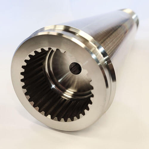
Mould and Die Vervaardiging
Vormmaak is een van die belangrikste toepassings van Sinker EDM.
Inspuitvorms, kompressie vorms, gietvorms, en ander gereedskapstelsels bevat dikwels diep holtes, smal ribbes, gestruktureerde oppervlaktes, en komplekse interne geometrieë.
EDM is veral waardevol na hittebehandeling omdat geharde vormstaal gemasjineer kan word sonder die snykragte wat met maalwerk geassosieer word.
Presisie gereedskap
Stampe, vorming sterf, Ekstrusie sterf, Stampgereedskap, en presisie-insetsels vereis dikwels stywe dimensionele toleransies en skerp interne kenmerke.
Sinker EDM maak die produksie van komplekse holtes moontlik wat veelvuldige gespesialiseerde snygereedskap benodig of ontoeganklik kan wees deur konvensionele bewerking.
Lugvaartkomponente
Lugvaartvervaardiging behels dikwels hoë sterkte, hittebestande legerings en komplekse interne geometrieë.
Sinker EDM kan gebruik word vir gespesialiseerde gereedskap, turbineverwante komponente, presisie toebehore, en moeilik-bewerkbare geleidende materiale.
Mediese vervaardiging
Presisie mediese gereedskap en geselekteerde metaalkomponente kan uiters fyn eienskappe vereis, komplekse holtes, en streng toleransies.
Sinker EDM is veral geskik vir die vervaardiging van vorms, vormingsgereedskap, en gespesialiseerde presisie komponente.
Motor- en energiebedrywe
Die proses word gebruik vir transmissiegereedskap, brandstofstelsel komponente, presisie sterf, turbine-verwante dele, en hoëprestasie industriële toerusting.
Elektronika en mikro-presisie-komponente
Mikro-EDM en presisie Sinker EDM tegnieke kan klein gleuwe produseer, holtes, verbindings, en ander fyn geleidende eienskappe waar konvensionele gereedskap te groot of meganies broos kan wees.
10. Konklusie
Sinker EDM is veel meer as bloot 'n alternatief vir maal vir harde materiale.
Dit is 'n fundamenteel verskillende vervaardigingsbeginsel wat elektriese energie in presisiemeetkunde omskakel, wat vorms en materiaalkombinasies moontlik maak wat geen meganiese snyproses kan bereik nie.
Sy unieke kombinasie van hardheid onafhanklikheid, nul snykragte, komplekse holtevermoë en spieëlafwerking oppervlakkwaliteit maak dit onvervangbaar in gereedskap- en matrysvervaardiging, lugvaart, mediese toestelle en presisie-ingenieurswese.
Die proses dra wel inherente afwykings: laer materiaalverwyderingskoerse, elektrodeslytasie-oorwegings en die vereiste vir geleidende werkstukke beteken dit is nie die optimale oplossing vir elke bewerkingstaak nie.
Wanneer dit korrek toegepas word - vir verharde materiale, komplekse interne holtes en hoë-presisie toepassings - sinker EDM lewer prestasie wat geen ander vervaardigingsproses kan ewenaar.
As kragopwekker tegnologie, beheerstelsels en outomatisering gaan voort, sinker EDM sal verder uitbrei na mikro-vervaardiging, mediese en halfgeleiertoepassings,
en geïntegreerde hibriede produksie werkvloeie, sy posisie as een van die grondliggende prosesse van moderne presisievervaardiging te versterk.
Vrae
Wat is die verskil tussen Sinker EDM en Wire EDM?
Sinker EDM gebruik 'n gevormde elektrode om blinde holtes en komplekse interne geometrieë te masjineer.
Draad EDM gebruik 'n voortdurend bewegende draad om deur elektries geleidende materiaal te sny en word hoofsaaklik vir profiele gebruik, slaan, skei, en deur-kenmerke.
Waarom word grafiet en koper algemeen as EDM-elektrodes gebruik??
Albei materiale bied goeie elektriese geleidingsvermoë en bewerkbaarheid.
Grafiet word wyd gebruik vir komplekse elektrodes en hoë-temperatuur EDM toepassings, terwyl koper uitstekende detailreproduksie en oppervlakkwaliteit in geskikte bewerkingstoestande kan verskaf.
Beskadig EDM die oppervlak van die werkstuk?
EDM produseer 'n termies geaffekteerde oppervlak en kan 'n hervormde laag vorm. Met behoorlik beheerde afwerking parameters, die aangetaste laag kan tot die minimum beperk word.
Kritieke komponente kan addisionele oppervlakafwerking of inspeksie vereis.
Hoe akkuraat is sinker EDM?
Hoë-presisie produksie sinker EDM masjiene hou tipies dimensionele toleransies van ±0.002 tot ±0.005 mm vir die meeste kenmerke, met ultra-presisie masjiene wat in staat is om ±0.001 mm onder beheerde toestande.
Akkuraatheid hang af van masjienstabiliteit, temperatuurbeheer en behoorlike elektrodeslytasiebestuur.
Kan Sinker EDM masjien geharde staal?
Ja. Sinker EDM kan enige geleidende materiaal masjineer, ongeag die hardheid. Dit is een van sy belangrikste voordele bo konvensionele bewerking.
Is Sinker EDM duur?
Die gereedskap (elektrode vervaardiging) is duur, en die masjientyd is duur as gevolg van stadige materiaalverwydering.
Nietemin, vir komplekse geometrieë en harde materiale, Sinker EDM is dikwels die mees koste-effektiewe opsie.

