Шөгінділер (Ішкі «Шаллинг» қуыстары, Керемет кеуектілік және микро-шөгу) дәлдіктегі ең жиі кездесетін және кейінгі ақаулардың бірі (Жоғалған балауыз) investment castings of stainless steels.
The defect is especially unacceptable in pressure-bearing components (клапандар, Сорғы денелері, Компрессорлық бөліктер) where leaks or fatigue failures may follow.
This article synthesises practical, engineering-grade experience and problem-solving tactics for eliminating or minimising shrinkage porosity in stainless-steel precision castings.
1. Root causes — what makes stainless-steel investment castings porous?
Кішірейту porosity in stainless steel Инвестициялық құйма is not a single-failure mode but the outcome of several interacting metallurgical and process factors.

Intrinsic drivers (alloy and solidification behaviour)
Large total solidification contraction
- Many stainless grades contract significantly on solidification. Typical volumetric shrinkage for common austenitics is roughly 4–6%, greater than many ferrous or non-ferrous alloys.
That creates a high demand for liquid metal feed to compensate volume loss.
Mushy zone & skin-forming solidification
- Stainless austenitics often display a narrow liquidus-to-solidus interval or form a rapidly solidified surface “skin”.
A solid shell can form early at the mould interface and trap interdendritic liquid in the centre, preventing feeding and producing interdendritic shrinkage.
Dendritic solidification and micro-segregation
- Solute elements segregate to interdendritic liquid during solidification.
That residual liquid freezes last and forms interconnected interdendritic networks; when feeding is inadequate, these areas form branched shrinkage cavities.
Relatively low molten fluidity
- Molten stainless typically flows less freely than aluminium or copper alloys (typical spiral fluidity lengths for stainless at ~1500 °C are on the order of 300–350 mm).
Poor flowability limits the ability to fill thin passages and to feed remote hot spots.
Alloying trade-offs
- High alloy contents (Әзірлеу, -Да) that improve corrosion or strength can also reduce fluidity and broaden the effective freezing behaviour for some compositions.
Some precipitation-hardening or duplex chemistries have wider freezing ranges and greater susceptibility to feeding problems.
Extrinsic drivers (жобалау, mould and process)
Design-induced hot spots
- Қалың бөлімдер, abrupt section changes, enclosed cavities and isolated masses freeze last and become hot spots.
If these regions are not properly fed, large centerline or interdendritic shrinkage develops. - Practical rule: abrupt thickness ratios (E.Г., 10 → 25 mm over a short distance) concentrate hot-spot risk.
Inadequate feeding and gating
- Risers/ingates that are undersized, incorrectly placed, or thermally starved cannot supply liquid metal to compensate localized shrinkage.
Absence of directional solidification paths (и.e., metal should solidify from the furthest point toward the riser) is a frequent root cause.
Mold shell and core issues
- Cold shell / poor preheat: insufficient shell preheat causes rapid heat extraction and shortens the feeding window.
- Overheated shell or inconsistent shell properties: can cause uneven solidification.
- Core damage or poor core venting: cores that fail, fracture or are not vented properly can block feeding or create trapped gas paths.
Poor feeder/riser thermal design
- No riser, too small a riser (modulus too low), or lack of exothermic/insulating measures means the feeder solidifies before or with the hot spot (и.e., feeding fails).
Pouring practice
- Insufficient superheat or low pour temperature → premature freezing and incomplete feeding.
- Excessive turbulence or splashing → oxide entrainment (bifilms), which interrupt metallurgical continuity and block fine interdendritic feeding channels.
Melt quality: gas and inclusions
- Dissolved gases (H₂, ₂) produce spherical gas pores; when combined with solidification shrinkage they aggravate feeding failure.
- Non-metallic inclusions and bifilms produce local blockages and act as nucleation sites for shrinkage networks. Inclusion-laden metal cannot feed as effectively into interdendritic networks.
Tooling and handling contamination
- Embedded particulate (wax residue, shell dust, steel swarf) or improper use of carbon-steel tools can seed localised corrosion sites or porosity during solidification and can interfere with feeding channels.
Compound failure modes — how causes interact
Porosity often results from multiple weaknesses acting together: E.Г., a thick hot spot + undersized riser + low pour temperature + trapped hydrogen. Any single cause can be compensated for if other controls are strong; multiple marginal conditions overwhelm feeding capacity and produce porosity.
2. Diagnosing the defect correctly
Before changing process or design, confirm what you’re seeing.
Simple diagnostics:
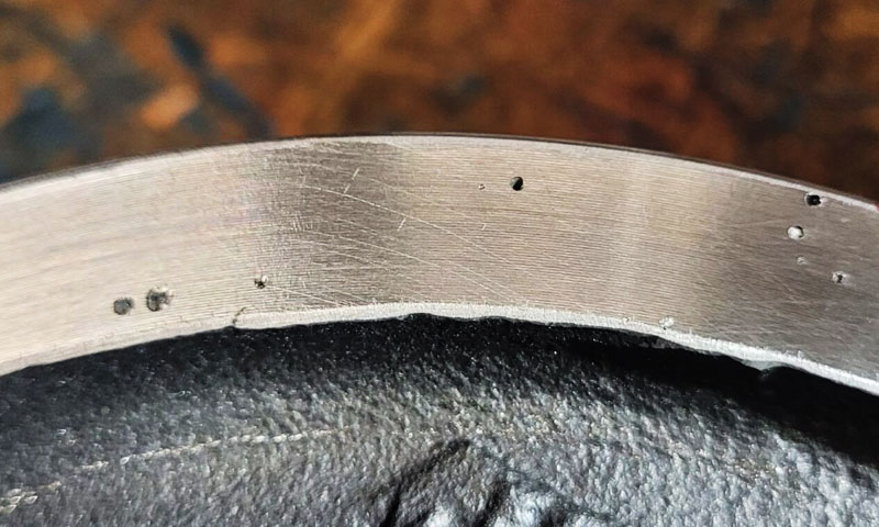
- Көру & sectioning: Cutting the casting through the suspect zone often shows a single large cavity (shrink) or a network of microcavities (microporosity).
- Рентгенография / Ц: Radiographs reveal cavity size and location; CT is excellent for complex internal geometries.
- Металлография: Microscopy can distinguish interdendritic shrinkage from gas porosity (spherical gas pores vs. branched interdendritic cavities).
- Химиялық & process review: Check hydrogen content, Тазалық еріген, pouring superheat, shell properties and gating design.
Interpretation rule: if cavities align with last-solidified paths and show dendritic walls → feeding deficiency. If pores are spherical and uniformly distributed → gas porosity.
3. Design measures (the first and most cost-effective line)
Most shrinkage problems are solved better in design than in process firefighting.

Promote directional solidification
- Place the feed (feeders/risers) so that solidification progresses from the furthest point toward the feeder.
In lost-wax, consider placement of external hot-tops, insulated feeders or exothermic sleeves on critical regions. - Simplify the cavity: reduce isolated hot spots (pockets that solidify last) by changing geometry, adding thermal thimbles or internal passages that act as feeders.
Avoid abrupt section changes and local hot spots
- Make wall thicknesses uniform where feasible; sudden thick sections are hot spots and require feeding.
- Филе қосыңыз, taper transitions and radii rather than sharp corners to reduce interfered heat flow and improve metal flow during filling.
Provide sacrificial feeding for internal cavities
- Design zero-interference external feeders or thin, removable extensions where internal feeding is impossible.
For internal cores, use ceramic core feeders (insulated) or design ethod to insert small feeder plugs. - Core chaplets & басу: ensure ceramic cores are supported but not over-constraining; chaplets must be designed so they don’t create fixed restraints on shrinkage.
4. Feeding system design — feed what the casting needs
Feeding is the heart of shrinkage prevention.
- Modulus (Chvorinov) rule: size risers so their modulus M_riser ≈ 1.2–1.5 × M_casting (largest hot spot). That ensures the riser solidifies after the casting feature it feeds.
- Riser types & placement: use top risers for vertical hot spots; side risers for distributed hot spots. Place risers to feed critical volumes directly.
- Exothermic and insulated risers: exothermic risers extend liquid life by 30-50%; insulated sleeves reduce heat loss — both increase feeding window without oversized risers.
- Multiple balanced ingates: for cylindrical or symmetric parts, use 3–4 ingates spaced circumferentially to distribute flow and reduce long last-to-solidify paths.
- Runner design: streamlined circular runners minimize flow resistance; avoid abrupt bends and sudden cross-section reductions. For small castings keep runner diameter ≥ 8 мм as a practical minimum.
5. Foundry process controls — control solidification timing
Small changes in process parameters have large effects.
- Shell preheat: for austenitic stainless (E.Г., 316/316Өшпін) preheat shells to 800-1000 ° C; for martensitic/PH grades use 600-800 ° C.
Proper preheat slows shell cooling and extends feeding time. Қызып кетуден аулақ болыңыз (>1100 ° °). - Pouring temperature & superheat: нысана ~100–150 °C above liquidus depending on alloy and section. Мысал: 316Өшпін poured at ~1520–1560 °C (±5 °C control for critical parts).
Higher temp increases fluidity (helps fill and feed) but increases shrinkage—balance is essential. - Бақыланатын салқындату: for heavy sections, insulating the shell (boxed cooling) for 2–4 hours after pour reduces thermal gradient and assists feeding. Rapid quench should be avoided.
- Gating and fill control: steady, laminar fill reduces cold laps and reduces premature freezing in critical flow paths.
6. Melt quality and metallurgy — remove nucleation sites
Gases and non-metallic inclusions in molten stainless steel act as nuclei for shrinkage porosity, so strict control of molten steel quality is essential:
- Refining Process Optimization: Use argon-oxygen decarburization (AOD) or vacuum oxygen decarburization (VOD) to refine molten steel, reducing carbon, күкірт, and gas content (H₂ ≤ 0.0015%, O₂ ≤ 0.002%).
For small-batch production, use a ladle refining furnace (LRF) with synthetic slags (CaO-Al₂O₃-SiO₂) to remove non-metallic inclusions. - Degassing and Deslagging: Perform argon blowing (flow rate 0.5–1.0 L/min per ton of steel) for 5–10 minutes before pouring to remove dissolved hydrogen.
Skim slag thoroughly from the ladle surface to prevent slag entrainment, which causes both shrinkage porosity and inclusions. - Control Alloy Additions: Avoid excessive addition of alloying elements (E.Г., Әзірлеу, -Да) that reduce fluidity. Use high-purity alloying materials (purity ≥ 99.9%) to minimize impurity introduction.
7. Advanced remediation & post-cast options
When preventive measures cannot fully eliminate shrinkage or when zero porosity is required:
- Ыстық изостатикалық басу (Сан): typical HIP cycle for stainless castings is 1100-1200 ° C -та 100-150 МПа -ге 2-4 сағат.
HIP collapses internal voids, achieves densities ≥ 99.9%, and reliably restores fatigue and pressure performance. HIP is the go-to solution for aerospace and pressure-critical parts. - Pressure/centrifugal casting: pressure solidification (applying pressure during cooling) or centrifugal variants can reduce porosity for certain shapes, though tooling and process changes are required.
- Localized repair: GTAW with ER316L filler can repair near-surface shrinkage after careful excavation and post-weld heat treatment; not suitable for internal defects in pressure zones.
- Combination approach: recast plus HIP is sometimes the only acceptable path for parts with recurring internal shrinkage.
8. Quality control, сынау & алу
Set objective criteria and verify compliance.
- NDT: radiography for internal voids, CT for complex geometries, UT for larger defects. Define acceptance (E.Г., no void > X mm, volumetric porosity < Y%).
- Metallographic analysis: confirm pore morphology (interdendritic vs gas) when troubleshooting.
- Mechanical testing: созық, Өткізіп жібер, іуу, and pressure/leak testing for pressure parts; HIP often requires tempered or re-solution treatment verification.
- Process logging & Зат: record shell preheat, еру & pour temperatures, degassing times, riser sizes and locations; statistically correlate variables to defect incidence.
9. Case study (ұқсас): eliminating valve-seat shrinkage in 316L valve bodies
Проблема: 316L valve bodies (Қысым рейтингі 10 МПа) exhibited shrinkage cavities at the valve seat (22 mm wall), қас себеп 15% ағас.
Actions
- Split the 22 mm hot mass into two ~10 mm sections with a 3 mm rib and a gradual transition.
- Added an exothermic top riser with modulus 2.0 см and repositioned two ingates to feed the hot spot.
- Increased shell preheat from 750 → 900 ° ° and set pouring to 1540 ± 5 ° C.
- Adopted VOD refining + argon degassing (8 мин) to reduce H₂ ≤ 0.001%.
Нәтиже: shrinkage incidence dropped to 2%, leakage eliminated, mechanical strengths rose ~8–10% — production yield and customer acceptance reached targets.
10. Key Principles and Best Practices for Shrinkage Porosity Prevention
This section condenses the engineering rules, proven tactics and operational standards that together prevent shrinkage porosity in stainless-steel investment castings.
Core principles (the “why” behind every action)
- Design to feed, not to look nice. The primary objective of the geometry is to enable directional solidification and uninterrupted liquid-metal flow into the last-to-solidify zones.
If the design creates inaccessible hot spots, process controls alone will not reliably prevent shrinkage. - Match feeding capacity to shrinkage demand. Use the modulus (Chvorinov) method to size risers so that feeders outlive the hot spot they feed (typical rule: M_riser ≈ 1.2–1.5 × M_casting).
- Control the thermal timeline. Solidification timing (shell preheat, pour temperature, insulation/cooling) defines the feeding window.
Manage those parameters deliberately to lengthen feeding where needed. - Eliminate porosity nucleation sites in the melt. Low hydrogen and low inclusion counts materially reduce the probability that trapped interdendritic liquid will form voids.
- Measure, simulate and iterate. Use solidification simulation up front and objective NDT & metallurgy after trials to converge quickly on a robust recipe.
- Escalate when necessary. When geometry or safety requirements demand near-zero porosity (Қысым бөлшектері, аэроғарыш), accept the economics of advanced remediation (HIP or pressure solidification) rather than accept recurrent scrap.
11. Қорытынды
Shrinkage porosity in Тот баспайтын болат investment casting is a complex defect driven by alloy solidification characteristics, casting structure, және технологиялық параметрлер.
Resolving it requires a systematic, multi-faceted approach—integrating structural optimization, feeding system design, Процесті басқару, and molten steel quality improvement.
By adhering to the principles of directional solidification, minimizing hot spots, and matching feeding capacity to shrinkage demand, manufacturers can significantly reduce shrinkage porosity and improve casting quality.
Сайып келгенде, successful shrinkage porosity resolution is not just a technical challenge but a commitment to rigorous quality control and continuous improvement across the entire casting lifecycle.

