
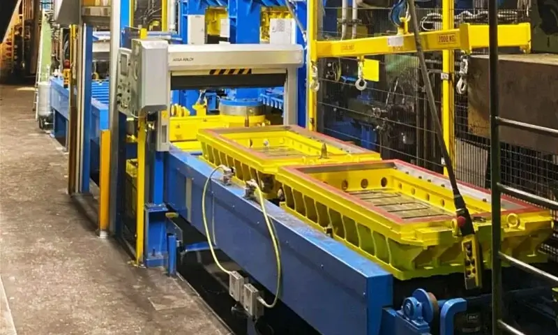
Нядаўна, I spent three days on a supplier’s production floor investigating subsurface pinholes and slag inclusions in high-carbon brake disc castings.
The foundry was equipped with a modern automatic production line, including high-pressure static molding and automatic pouring systems.
Despite the advanced equipment, the defect rate was increasing, and the root causes remained unclear.
This situation highlights an issue I have encountered repeatedly in foundry production: advanced automation does not automatically guarantee better casting quality.
On a manual line, experienced operators can often recognize changes in sand condition, якасць формы, and pouring behavior through direct observation.
On an automated line, аднак, equipment repeats programmed operations consistently, even when process conditions such as sand moisture, inoculant condition, or core quality are outside the required range.
Without proper process knowledge and parameter control, a highly automated line can reproduce the same defects across large production batches.
This article summarizes the investigation approach, explaining how to distinguish subsurface pinholes from slag inclusions and systematically identify their causes across melting, inoculation, фармовачны пясок, ядры, варотны, наліць, and equipment management.
1. Identifying Pinhole and Slag Defects in Brake Disc Castings
Before changing production parameters, engineers should determine whether the defect is gas-related or inclusion-related.
Although pinholes and slag inclusions may occur in similar areas, their morphology and distribution provide important clues.
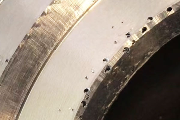
Subsurface Pinhole Defects
Subsurface pinholes are small gas cavities located just beneath the casting surface. In high-carbon brake discs, they are commonly found approximately 1–4 mm below the surface.
Тыповыя характарыстыкі ўключаюць:
- Relatively round or smooth cavities.
- Smooth internal pore walls.
- Concentration beneath the casting surface rather than exclusively on the exposed surface.
- Recurring defects near ventilation cores, upper mold regions, or areas with poor gas evacuation.
- Pores that may become visible during machining, драба, або аздабленне паверхні.
Pinhole formation is commonly related to gas evolution during pouring and solidification.
Moisture in molding sand, insufficiently cured resin cores, damp inoculants, and excessive gas generation can all contribute.
Dissolved gases and melt reactions may also play a role, depending on the iron chemistry and pouring conditions.
In highly compacted green sand molds, gas generated near the metal-mold interface may not escape quickly enough.
When the pressure of the accumulating gas exceeds the local conditions that resist its movement, gas can penetrate the liquid or partially solidified metal and form subsurface cavities.
Slag and Non-Metallic Inclusion Defects
Slag defects have a different appearance and formation mechanism. They generally contain non-metallic materials such as oxide films, silicate residues, sulfide-rich inclusions, or other foreign particles.
Тыповыя характарыстыкі ўключаюць:
- Irregular cavity shapes rather than consistently rounded pores.
- Dark or non-metallic material visible inside the defect.
- Rough or uneven internal surfaces.
- Concentration near the gating system, above ventilation cores, around disc-face radii, and on upper casting surfaces.
- Defects that may be exposed during machining or sectioning.
In high-carbon gray iron production, slag inclusions may originate from oxidation during melting and pouring, incomplete slag removal, inoculation reactions, mold and core coatings, or loose sand and refractory particles.
The gating system can also transport these contaminants into the mold cavity if its slag-retention capacity is inadequate.
Pinhole vs. Уключэнне дзындраў: Асноўныя адрозненні
| Evaluation Item | Subsurface Pinholes | Шлаковые ўключэння |
| Typical location | Approximately 1–4 mm below the surface | Near runners, above ventilation cores, upper surfaces, and casting radii |
| Абрыс | Generally round or oval | Irregular and uneven |
| Internal appearance | Smooth cavity walls | Dark inclusions, аксідныя плёнкі, or silicate residues |
| Main formation mechanism | Gas generation and entrapment | Акісленне, slag carryover, and non-metallic contamination |
| Common contributing factors | High sand moisture, нізкая праходнасць, core gas, damp inoculant | Inadequate slag removal, акіленне, damaged filters, coating or sand residues |
| Primary control measures | Reduce gas generation and improve venting | Improve melt cleanliness, slag separation, фільтраванне, and mold cleanliness |
Важны: Defect appearance alone is not always sufficient for a definitive diagnosis. Some gas-related cavities can have irregular shapes, while oxide films may appear as thin discontinuities rather than obvious slag-filled holes.
For recurring defects, раздзелка, metallographic examination, і, дзе гэта дарэчы, chemical analysis of inclusions should be used to confirm the mechanism.
2. Melt Preparation and Molten Iron Quality Control
Melt quality is the first major control point for preventing both pinholes and slag inclusions.
In high-carbon brake disc production, raw material cleanliness, тэмпература плаўлення, час вытрымкі, раскіслення, выдаленне дзындраў, and sulfur content all influence the final casting quality.
Raw Material Selection and Charge Preparation
High-carbon gray iron brake discs commonly use pig iron, steel scrap, and carburizing agents to achieve the target carbon content and melt chemistry.
Аднак, raw material contamination can introduce significant sources of gas and non-metallic inclusions.
Particular attention should be paid to:
- Steel scrap: Remove excessive rust, змазваць, фарбы, вільгаць, and other surface contaminants before charging.
- Returns and rejected castings: Sort return materials separately and prevent contamination with resin sand, coated sand, burned-on binder residues, or other molding materials.
- Carburizing agents: Select graphite-based carburizers with low sulfur, нізкай зольнасці, and low volatile content.
- Charge cleanliness: Avoid introducing excessive rust, бруд, and non-metallic materials into the furnace.
Low-quality carburizing agents may introduce additional volatile substances and ash-forming impurities. These can increase gas generation and slag formation, making subsequent melt treatment more difficult.
Foundries should establish incoming material inspection standards and maintain traceability for different batches of scrap, pig iron, and carburizers.
Consistent charge quality is more reliable than attempting to correct contaminated melt through downstream treatment.
Control Tapping Temperature and Holding Time
For the production conditions described in this case, the recommended tapping temperature is:
Reference process range
1,490–1,510°C
Temperature control is important for both inclusion separation and gas-related defect prevention.
If the tapping temperature is too low, certain reaction products and non-metallic inclusions may have insufficient time or favorable conditions to separate and float to the surface. Slag removal may consequently become less effective.
After tapping, the ladle should be allowed to stand for approximately 60–90 seconds to provide time for floating slag and inclusions to rise toward the metal surface.
Аднак, excessively high temperatures and prolonged overheating should also be avoided. Severe overheating can increase oxidation and alter the gas behavior of molten iron.
Under unsuitable carbon, кісларод, and pouring conditions, CO-related gas defects may develop during solidification.
The objective is not to maximize temperature, but to maintain a suitable thermal window that supports melt treatment, slag separation, and stable pouring.
Deoxidation and Slag Removal
Deoxidation and slag removal are essential for controlling oxide-related inclusions.
One practical approach is to add a suitable silicon-manganese pre-deoxidizer during tapping. This helps control oxygen-related reactions in the molten iron.
The exact addition rate must be determined according to the melt chemistry, treatment practice, and the manufacturer’s process specifications.
Slag-removal agents should be introduced and used according to their operating requirements. Simply scattering a small quantity over the metal surface is not always sufficient.
A more effective procedure includes:
- Adding the appropriate slag-removal agent.
- Allowing the treatment to react and bring inclusions together.
- Providing sufficient time for slag to float.
- Thoroughly skimming the ladle surface before pouring.
- Preventing removed slag from re-entering the metal during transfer.
Incomplete skimming is a common cause of recurring slag defects on automatic molding lines. Even when the gating system includes a filter, excessive slag entering the pouring stream can overwhelm the filtration system.
Maintain an Appropriate Sulfur Content
For the high-carbon brake disc process described in the source material, the sulfur content is controlled within:
S = 0.05–0.09%
Sulfur influences the formation of manganese sulfide and the response of gray iron to inoculation.
Both excessively low and excessively high sulfur levels may create production difficulties.
- Sulfur too low: The inoculation response and graphite nucleation behavior may become less favorable, depending on the base iron chemistry and treatment practice.
- Sulfur too high: Excessive sulfide formation may increase the amount of non-metallic inclusions and contribute to slag-related defects.
Sulfur should not be controlled in isolation. Its relationship with manganese, вугляродны эквівалент, крэмнім, кісларод, and inoculation practice must also be considered.
A stable sulfur range, combined with consistent melt treatment, helps improve graphite formation and reduce the risk of inclusion-related defects.
3. Inoculation System: A Critical Factor in Subsurface Pinhole Prevention
Inoculation is essential for controlling graphite nucleation, reducing chill tendency, and achieving consistent mechanical and thermal properties in gray iron brake discs.
Аднак, on automatic high-pressure molding lines, the inoculation system can also become a source of process instability if addition rate, матэрыяльны стан, or feeding consistency is poorly controlled.
Many automatic production lines use in-stream inoculation, which offers good process integration and repeatability.
Тым не менш, an unstable inoculation process may contribute to recurring subsurface pinholes and inconsistent casting quality.
Avoid Excessive Inoculant Addition
More inoculant does not necessarily produce better castings.
Excessive addition can increase the amount of reaction products and inclusions introduced into the melt.
Depending on the inoculant composition and treatment conditions, it may also increase the burden on the melt-cleaning process.
When the mold has limited gas permeability, any additional gas generated by damp materials or unstable treatment conditions becomes more difficult to evacuate. The combined effect can increase the risk of subsurface porosity.
The inoculant addition rate should therefore be determined according to the base iron chemistry, target metallurgical structure, inoculant type, і вытворчыя патрабаванні.
Avoid increasing the addition rate simply to compensate for inconsistent inoculation results.
Maintain Stable In-Stream Inoculation
In-stream inoculation requires consistent material feeding and a stable molten iron flow.
Common problems include:
- Interrupted inoculant feeding.
- Inconsistent addition rates.
- Localized accumulation caused by concentrated or uneven feeding.
- Inoculant particles that do not dissolve or distribute uniformly.
- Excessive variation between successive molds.
These problems can produce inconsistent graphite nucleation and metallurgical properties across a production batch.
The feeding equipment should be calibrated regularly, and the inoculant should be distributed continuously throughout the pouring stream.
Operators should also check the relationship between pouring rate and inoculant feeding rate to prevent localized over-addition.
Keep Inoculants Dry
Moisture contamination is a particularly important issue.
Damp inoculants can introduce water into molten iron, causing rapid vaporization and increasing the risk of gas-related defects. This problem becomes more serious when the mold has limited permeability.
Inoculants should be stored in dry conditions, protected from moisture during transportation and handling, and inspected before use.
Any material showing signs of moisture absorption or improper storage should be isolated and handled according to the supplier’s requirements.
Verify Inoculation Effectiveness
Inoculation quality should be evaluated through more than the addition rate alone.
Useful controls include:
- Monitoring the actual inoculant feeding rate.
- Checking the consistency of the pouring stream.
- Comparing chill tendency and fracture appearance.
- Evaluating graphite morphology and distribution through metallographic examination.
- Monitoring hardness and other relevant mechanical or thermal performance indicators.
For brake discs, stable graphite distribution is important because it influences thermal conductivity, damping behavior, wear characteristics, and resistance to thermal cracking.
Inoculation control should therefore be treated as both a casting-defect prevention measure and a metallurgical quality requirement.
4. Green Sand Molding: Managing the Permeability Limitations of High-Pressure Molding Lines
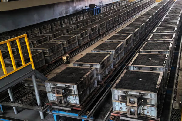
High-pressure static molding provides excellent dimensional accuracy and mold strength, but its dense sand structure can restrict gas escape.
For high-carbon brake disc castings, inadequate permeability and poor venting can allow mold-generated gases to enter the molten iron, increasing the risk of subsurface pinholes.
Moisture Control
Maintain green sand moisture at 3.0–3.5%, with minimal fluctuations. Excessive moisture increases gas generation when the mold contacts molten iron.
Because high-carbon iron is poured at relatively high temperatures and static-pressure molds are densely compacted, the generated steam may not escape quickly enough, increasing the risk of subsurface pinholes.
Permeability Management
Test sand permeability regularly and monitor the accumulation of excess fines and dead clay in the return sand. These materials can block gas-flow channels and reduce mold permeability.
Return sand temperature also requires attention. Hot sand entering the molding machine can affect mold-surface moisture conditions and increase gas generation during pouring.
Вось чаму, effective return sand cooling and stable sand preparation are essential.
ВЫКЛЮЧЭННЕ ФОРМА
The ring-shaped geometry of brake discs creates specific venting requirements. Dedicated vent plugs should be arranged around the upper mold, riser locations, and ventilation core positions to provide clear gas escape paths.
Vent plugs must be cleaned regularly. Blocked vents cannot discharge gas effectively and may create a false impression that the mold has adequate ventilation.
Their condition should therefore be included in routine tooling inspections.
Mold Surface Stability
Coal dust addition must be properly balanced. Insufficient coal dust can allow molten iron to wet the mold surface, increasing the risk of metal penetration and slag-related defects.
Excessive addition, аднак, increases gas generation and can trigger pinhole defects.
Use low-gas-generation coal dust and control the total gas output of the molding system rather than adjusting individual additive percentages in isolation.
Stable sand properties and controlled gas generation are essential to reducing defects in high-pressure molding lines.
5. Resin-Bonded Ventilation Cores: A Major Source of Gas and Slag Defects
The resin-bonded vane core is one of the highest-risk components in vented brake disc production.
Inadequate curing, improper coating, or insufficient venting can introduce both gas and non-metallic inclusions into the casting.
Ensure Complete Core Curing
Full core curing is essential. A core that is hard on the surface but remains soft internally may continue to release gas during pouring.
If the generated gas cannot escape through the core venting system, it can enter the molten iron and cause core-side pinholes.
Control Core Coating Application and Drying
Use a low-gas-generation, high-temperature zircon-based coating suitable for the pouring conditions. Apply it uniformly and avoid excessive coating thickness.
The coating must be completely dry before mold closing. Residual moisture and binder can generate gas during pouring.
У дадатак, poorly dried or excessively thick coatings may peel off and enter the casting, forming coating-related slag defects.
Provide Effective Core Venting
Gas should be discharged through the core print rather than escaping into the casting cavity.
Cut venting channels in the core print and embed vent rope inside the core to establish a continuous gas escape path.
Clean the Mold Before Closing
Before closing the mold, use compressed air to remove loose sand and detached coating particles from the cavity and core surface.
These contaminants can be carried into the molten iron and form slag-like inclusions or surface defects.
Пасля ачысткі, close the mold promptly to prevent loose sand or coating debris from re-entering the cavity.
6. Gating System and Pouring Process: Controlling Slag Entrapment and Gas Entrapment
The gating system is the final control point between molten iron preparation and mold filling.
Even when the melt is clean, the sand system is stable, and the cores are properly prepared, poor gating design or unstable automatic pouring can introduce slag, аксіды, and gas into the casting.
For high-carbon brake discs, the annular geometry and internal ventilation passages make flow distribution particularly important.
The gating system should fill the cavity smoothly, avoid direct impact on the cores, and provide sufficient opportunities for slag separation.
Use Bottom-Filling or Step-Gating Arrangements Where Appropriate
For brake disc castings, bottom-filling or stepped gating arrangements are often worth evaluating because they can reduce the impact of the incoming metal stream and support more controlled mold filling.
Potential benefits include:
- Reducing direct metal impact on the mold and ventilation cores.
- Limiting turbulence and air entrainment.
- Reducing the risk of oxide-film formation during filling.
- Improving metal distribution across the annular cavity.
- Reducing the possibility of sand or coating erosion.
The runner should also be designed with sufficient length and suitable geometry to support flow stabilization.
Дзе трэба, add runner extensions or dedicated slag-collection pockets to retain contaminants before the metal reaches the casting.
Ingate positions should be distributed according to the brake disc geometry. A single concentrated entry point may create localized high velocity and directly damage the sand core.
Multiple appropriately sized ingates can provide more balanced filling, although their number and position must be verified through flow analysis and production trials.
Add Slag Traps and Improve Runner Cleanliness
Slag traps and runner extensions provide additional opportunities for floating slag and larger inclusions to remain outside the casting cavity.
A practical gating design should consider:
- Adequate runner volume and cross-sectional geometry.
- Slag-collection pockets positioned before the ingates.
- Smooth runner transitions that avoid unnecessary turbulence.
- Ingate locations that do not draw surface contaminants directly into the cavity.
- Easy removal and cleaning of accumulated slag from the gating system.
Аднак, a longer runner does not automatically guarantee better slag removal. If the flow velocity is excessive or the runner geometry is poorly designed, inclusions may still be carried into the mold.
The effectiveness of the slag trap should be evaluated through actual casting results, inclusion distribution, і, дзе гэта дарэчы, flow simulation.
Control Pouring Temperature
For the high-carbon brake disc process described in the source material, the recommended pouring temperature is:
Reference process range
1,360–1,400°C
Pouring temperature affects fluidity, filling time, oxidation behavior, and the interaction between molten iron and the mold.
If the pouring temperature is too high:
- Oxidation and metal-mold reactions may become more severe.
- The amount of oxide-related contamination may increase.
- Sand and coating reactions may intensify.
- Gas-related defects may become more likely under unfavorable melt and mold conditions.
If the pouring temperature is too low:
- Molten iron may lose fluidity before filling thin or remote sections.
- Slag and inclusions may become less mobile and harder to separate.
- Cold shuts and misruns may occur.
- The filling process may become less consistent.
The target should be selected according to casting weight, Таўшчыня сцяны, вугляродны эквівалент, pouring time, тэмпература формы, and the actual thermal conditions of the production line.
The range of 1,360–1,400°C is a process reference, not a universal specification for every high-carbon brake disc.
Match Automatic Pouring Speed to Mold-Filling Requirements
Automatic pouring improves repeatability only when the pouring parameters are properly calibrated.
Excessive pouring speed can cause:
- Turbulent filling and air entrainment.
- Oxide-film formation.
- Sand and core erosion.
- Insufficient time for mold gases to escape.
- Increased risk of slag being carried into the casting.
Pouring too slowly can also create problems. The metal may lose excessive heat during filling, allowing oxide films and surface slag to develop while increasing the risk of cold shuts and incomplete filling.
The pouring curve should therefore match the gating system’s flow capacity and the mold’s gas-evacuation characteristics.
For automatic pouring lines, engineers should verify:
- Actual pouring weight and pouring time.
- Metal stream stability.
- Pouring rate at the beginning, middle, and end of the cycle.
- Consistency between successive molds.
- Relationship between pouring rate and in-stream inoculant feeding.
- Temperature variation during the production shift.
Do not assume that the pouring machine’s programmed parameters accurately represent actual process conditions. Periodic calibration and observation of the real metal stream are essential.
Install and Inspect Pouring Filters
The pouring basin can be equipped with a slag-retaining weir and a suitable filter to reduce the transfer of non-metallic inclusions into the mold.
For the production system described, the filter is an important final inclusion-control measure. Аднак, it should not replace proper melt cleaning and runner design.
Filter inspection should include:
- Checking for cracks, паломка, and incomplete installation.
- Confirming that the filter is suitable for the molten iron temperature and flow rate.
- Preventing movement or displacement during pouring.
- Ensuring that the filter does not create excessive flow resistance.
- Replacing damaged or contaminated filters before production.
A broken or improperly seated filter may allow slag to bypass the filtration area, resulting in a sudden increase in inclusion defects across an entire production batch.
The filter must also be matched to the gating system. An undersized or excessively restrictive filter can slow filling and increase the risk of misruns, while an unsuitable pore structure may provide inadequate inclusion retention.
7. Equipment and Production Management: Controlling Process Stability on Automatic Lines
On an automatic high-pressure molding line, stable casting quality depends not only on equipment precision but also on consistent control of sand conditions, mold sealing, production timing, and operating procedures.
Even small process deviations can be repeated across large production batches, making routine equipment and shop-floor management essential.
Control Return Sand Temperature
The return sand cooling system should maintain sand temperature at ≤45°C before it enters the molding machine.
Excessively hot sand can cause surface moisture to evaporate during mold preparation. When the mold contacts molten iron, the resulting moisture and gas generation may contribute to subsurface pinholes.
Regularly monitor sand temperature at the molding machine inlet rather than relying solely on the cooling system’s operating settings.
Cooling performance should remain stable during continuous production, especially when return sand volume and ambient conditions change.
Maintain Reliable Mold Closing and Parting-Line Sealing
On a static-pressure molding line, the parting-line seal must be properly maintained.
Poor sealing can cause molten iron run-out and allow gas to escape through unintended paths, disrupting the designed mold-filling and venting conditions.
Inspect the parting surfaces, mold alignment, sealing components, and clamping condition regularly.
Any wear, дэфармацыя, or accumulated sand on the parting line should be corrected before production continues.
Control the Time Between Molding, Асноўная зборка, і Наліванне
Avoid excessive delays between mold preparation, core assembly, mold closing, і заліванне.
Exposed molds and cores can absorb moisture from the surrounding environment, particularly under humid shop-floor conditions. This increases gas generation during pouring.
Establish a reasonable production interval and prioritize pouring molds within the specified holding time.
Molds left overnight or exposed for extended periods should be inspected and, дзе трэба, reconditioned before use.
Use Comparative Trials to Identify Root Causes
When defects persist, controlled comparative trials are more reliable than changing several process parameters simultaneously.
Напрыклад:
- To investigate slag defects: Compare the current practice with a trial using dry inoculant and more thorough molten iron skimming.
Use the same ladle of molten iron where practical to minimize differences in melt condition. - To investigate pinholes: Add or modify mold vent plugs while keeping other process parameters unchanged, then compare the defect rate.
Record the trial conditions, defect locations, and inspection results. Changing one major variable at a time makes it easier to determine which adjustment produces a measurable improvement.
The objective is to establish a repeatable production process, not simply to reduce defects temporarily.
On automatic lines, stable sand preparation, reliable equipment condition, controlled production timing, and systematic process verification are all necessary to maintain consistent brake disc casting quality.
8. Fast Troubleshooting Guide: How to Locate the Source of Pinhole and Slag Defects
When pinhole or slag defects appear in high-carbon brake disc castings, troubleshooting should follow a systematic sequence.
Start with the defect location, check the most likely process-related causes, and then make targeted adjustments.
Крок 1: Identify the Defect Location
- Defects concentrated near the core: Check core gas generation, стан пакрыцця, and core venting first.
- Defects concentrated on the upper surface or near risers: Inspect cavity venting and the condition of the mold vent plugs.
- Defects distributed along the runner path: Investigate slag carried by the molten iron and possible pouring basin filter failure.
Крок 2: Check the Most Likely Causes
Before changing process parameters, inspect the basic production conditions:
- Green sand moisture and temperature.
- Stream inoculant condition, especially moisture absorption.
- Core curing and drying condition.
- Pouring basin filter condition and installation.
These factors are relatively easy to verify and can directly contribute to pinhole or slag defects.
Крок 3: Optimize the Main Process Controls
If the initial checks do not identify the cause, focus on the relevant process improvements:
- Improve molten iron holding and deslagging procedures.
- Add or modify mold vent plugs where gas evacuation is insufficient.
- Optimize runner and slag trap design to reduce slag entering the mold cavity.
Крок 4: Fine-Tune Pouring and Molding Parameters
After addressing the primary causes, adjust pouring temperature, хуткасць залівання, and coal dust addition as needed.
These parameters should be optimized through controlled production trials rather than changed simultaneously.
The key is to diagnose defects by location and verify the most likely causes before adjusting the process.
This approach helps avoid unnecessary parameter changes and makes defect reduction more efficient.
9. Чаму выбраць Гэтае for High-Quality Gray Iron Brake Disc Castings?
Producing high-quality high-carbon gray iron brake discs requires more than advanced molding equipment and automatic pouring machines.
It requires a coordinated understanding of melt metallurgy, inoculation, green sand behavior, resin core preparation, канструкцыя варот, і кантроль зацвярдзення.
Каля ГЭТА тэхн, casting quality is approached through systematic process management, from raw material selection and molten iron treatment to mold preparation, наліць, і канчатковая праверка.
For brake disc applications, particular attention should be paid to controlling subsurface pinholes, шлаковые ўключэння, кансістэнцыя памераў, and the internal quality of ventilated structures.
Whether developing conventional or ventilated brake discs, Гэтае focuses on identifying defect mechanisms and improving the relevant process parameters rather than relying on isolated adjustments.
Звяжыцеся з гэтым to discuss your custom cast iron casting requirements and explore practical solutions for achieving more stable production and consistent casting quality.
10. Conclusion
Pinhole and slag defects in high-carbon brake disc castings are rarely caused by a single factor.
On high-pressure static molding lines, they often result from the interaction of molten iron quality, inoculation conditions, пранікальнасць цвілі, resin core gas generation, канструкцыя варот, and automatic pouring stability.
The most effective prevention strategy is to distinguish the defect type first and then investigate the corresponding process variables.
- For subsurface pinholes: Control moisture, inoculant condition, core curing, пранікальнасць цвілі, and gas-escape paths.
- For slag inclusions: Improve raw material cleanliness, ladle skimming, раскіслення, runner slag traps, and filter integrity.
- For recurring defects across production batches: Review automatic pouring parameters, sand system stability, equipment sealing, і час працэсу.
The central engineering principle is straightforward: do not sacrifice mold strength simply to increase permeability.
Control the amount of gas generated, provide dedicated escape routes, and prevent non-metallic contaminants from entering the cavity.
And remember the golden rule of automated lines: the machine will do exactly what you tell it to do, every cycle.
If the process is right, it will produce good castings forever. If the process is wrong, it will produce bad castings faster than any manual line ever could.